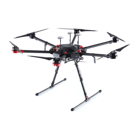
Embention TS150 User manual

TS150
Embention
Dec 23, 2020


Contents
1 Installation 1
1.1 System Overview ............................................. 3
1.2 Components ............................................... 4
1.3 Dimensions and weights ......................................... 10
1.3.1 Power Station .......................................... 10
1.3.2 Ground Control Station ..................................... 10
1.3.3 Cable .............................................. 10
1.3.4 Multirotor ............................................ 11
1.4 Connections and controls ........................................ 11
1.4.1 Power Station .......................................... 11
1.4.2 Ground Control Station ..................................... 13
1.4.3 Multicopter-Cable ........................................ 14
2 Operation 17
2.1 System check ............................................... 17
2.2 Operation window ............................................ 19
2.3 Artificial Vision controls ......................................... 20
2.4 Settings panel ............................................... 21
2.5 Rendesvouz configuration ........................................ 24
2.6 Geolocation configuration ........................................ 29
2.7 Geotagging configuration ........................................ 31
2.8 Telemetry ................................................. 32
2.9 Quick Operation ............................................. 34
3 Maintenance 41
3.1 Preventive Maintenance ......................................... 41
3.2 Pre-flight Checking ............................................ 42
3.3 Post-flight ................................................ 47
3.3.1 Cleaning the system ....................................... 47
3.4 Periodical events ............................................. 48
3.4.1 Cable unrolling ......................................... 48
3.4.2 Tether arms change ....................................... 48
3.4.3 Preventive Battery Replacement Unit change ......................... 53
3.4.4 Overhaul ............................................ 53
3.5 Corrective Maintenance ......................................... 54
3.5.1 Propeller replacement ...................................... 54
3.5.2 Landing Gear replacement ................................... 58
i

3.5.3 Battery Replacement Unit maintenance ............................ 62
3.6 Conditions Of Storage .......................................... 64
3.7 Flight Hours Record ........................................... 64
3.8 Maintenance Record ........................................... 65
4 Technical 67
4.1 Part List ................................................. 68
4.1.1 Multicopter ........................................... 68
4.1.1.1 Overview ....................................... 68
4.1.1.2 Exploded View .................................... 69
4.1.1.3 List ........................................... 70
4.1.2 Ground Station ......................................... 71
4.1.2.1 Overview ....................................... 71
4.1.2.2 Exploded View .................................... 72
4.1.2.3 List ........................................... 72
4.1.3 Power Station .......................................... 73
4.1.3.1 Overview ....................................... 73
4.1.3.2 Exploded View .................................... 76
4.1.3.3 List ........................................... 76
ii

1

TS150
CHAPTER 1
Installation
2 Chapter 1. Installation

TS150
Ground Station and Multicopter
1.1 System Overview
Multicopter, GS and PS
1.1. System Overview 3

TS150
Multicopter Isometric View
Multicopter Multi View
1.2 Components
Next figure shows the assembly of the system:
4 Chapter 1. Installation

TS150
Assembly
The main components of the system are:
1. Power station (PS): This is the case where the 230V AC wall input has to be connected and where the multirotor
must be transported.
1.2. Components 5

TS150
Power station
6 Chapter 1. Installation

TS150
Power Station with multicopter inside
2. Ground station (GS): is the place where the multirotor operates, it is ready to be used with Autopilot Veronte
and Veronte PIPE systems.
1.2. Components 7

TS150
Ground Control Station
8 Chapter 1. Installation

TS150
Top View
3. Multicopter: Y6 coaxial tricopter including our integrated gimbal. Custom payloads can be installed instead of
the gimbal.
Multicopter
1.2. Components 9

TS150
1.3 Dimensions and weights
1.3.1 Power Station
Power Station Dimensions (mm)
Multirotor inside 63.5Kg
Empty 51.5Kg
Power 4000W
1.3.2 Ground Control Station
Ground Control Station and Power Station have the same dimensions.
Weight 53Kg
Power 600W
1.3.3 Cable
Length 150m
Diameter 4mm
Weight/m 0.0244Kg/m
Total weight 3.66Kg
10 Chapter 1. Installation

TS150
1.3.4 Multirotor
Multirotor 9.55Kg
+Gimbal 11.3Kg
+Gimbal + Cable 14.96Kg
1.4 Connections and controls
1.4.1 Power Station
Power Station Connections
1.4. Connections and controls 11

TS150
Power Station Connections
A 3 pin connection 230V AC power output to GS
B 2 pin connection High voltage power output to GS
C Ground Switch Turns on/off the 230V AC power output to feed the GS
D Air Switch Turns on/off high voltage power output to feed the multicopter
E Emergency button Stops the system immediately (will activate emergency landing)
F 4 pin connection 230V AC input
12 Chapter 1. Installation

TS150
1.4.2 Ground Control Station
Ground Control Station Connections A
G Restart button Manually turns on/off the internal computer
H HDMI port Direct video output from the internal computer
I Ethernet port RJ45 LAN connector
J USB To connect any peripheral to the internal computer
K Fan and filter To refrigerate the station
1.4. Connections and controls 13

TS150
Ground Control Station Connections B
L 3 pin connection 230V AC input to GS
M 2 pin connection High voltage input to GS
N ROLL button Cable manual roll
O Stop button Brake enable / Brake disable
1.4.3 Multicopter-Cable
Cable-Muticopter Connection
14 Chapter 1. Installation

TS150
Plug the connector from the GS into the multicopter.
Warning: It is important to ensure that there are at least 2 meters of cable out of the ground station before taking
off. This will avoid problems in the operation.
1.4. Connections and controls 15

TS150
16 Chapter 1. Installation
Other manuals for TS150
1
Table of contents
Other Embention Drone manuals
