Sabre DL700 User manual

1
USER MANUAL - DL700
SMART LOCK
www.sabre.com.au
Please read this manual carefully before installation and keep it for future reference.

INTRODUCTION
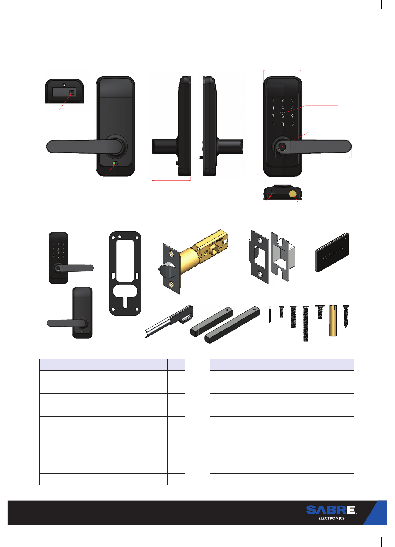
Lock detail
Contents
Specifications
INSTALLATION
STEP 1 - Latch Installation
STEP 2 - Handing
STEP 3 - External Lever Installation
STEP 4 - Internal Lever Install
Backing Plate Install
Internal Lever - Install
Assembly
Installation
STEP 6 - Dustbox and Striker Plate
Installation
STEP 5 - Battery and Cover Installation
Internal Lever - Install Batteries
Internal Lever - Installation
STEP 7 - System Initialisation
STEP 8 - Registration
STEP 9 - Connect to your phone
STEP 10 - Add locks
STEP 11 - User Management
OPERATION
FAQS
Bluetooth management
Setting Passcode
Send e-Key
Add card
Add fingerprint
e-Key management
Passcode management
Unlock records
STEP 12 - Privacy Function
STEP 13 - Gateway management
(Optional)
Add Gateway
Manual
3
3
4
8
8
8
8
8
10
10
11
5
5
6
6
7
7
3
INTRODUCTION
Lock detail
Contents
No. Name Qty No. Name Qty
1 Internal Lever 1 11 M3*10mm back Panel Screws 3
2 External Lever 1 12 M5*25mm Screw 2
3 Waterproof Gasket 2 13 M5*40mm Screw 2
4 60/70mm Deadlatch 1 14 Sliding Screws Connector M5 1
5 Strike Plate inc. Strike Box 1 15 Screw Stubs M5*35mm 2
6 Card 2 16 Strike Plate Screws 8g x 25mm 2
7 Mechanical Key 2 17 Deadlatch Screws 8g x 25mm 2
8 60mm Spindle 1 18 Installation Template 1
9 80mm Spindle 1 19 User Manual 1
10 Spindle Split Pin 1
Manual locking button
Keypad and card read
Key override
USB emergency
power plug
Reset button
72mm
144mm
190mm
73mm
Thumbprint recognition
1
2
3 4 5 6
7 8 9 10 11 12 13 14 15 16, 17

4
Specifications DL-700
Lock Weight 3kg Doors Stile Minimum 60mm Backset – 100mm
70mm Backset – 110mm
Materials Aluminium Alloy Door Thickness 35mm – 65mm
Locking Options Bluetooth
Fingerprint(option)
Password
Card
Mechanical key
Gateway(option)
Data Capacity Fingerprint: 200 Users
Passcode: 150 Users
Card: 200 Users
Colour Black Operating Temperature -10°C – 55°C
Low Voltage Warning 4.8V Operation Humidity 0-95%

5
Set up your lever handle direction to suit your door.
Prepare door using fitting template
supplied and install deadlatch in the current
orientation to the doors opening and closing
External Lever Handing
External LH
Internal RH
External RH
Internal LH
Rotate Lever 180°and replace handing screw
Rotate Lever 180°and replace handing screw
Internal Lever Handing
INSTALLATION
STEP 2 - Handing
STEP 1 - Latch Installation

6
STEP 4 - Internal Lever Install
Backing Plate Install Internal Lever - Install
• Attach rubber gasket to internal plate
• Place external cable clip through internal plate
slot and secure plate by screwing M5x fixing
screws into external lever threaded posts
• Connect the internal lever cable clip to the external
lever cable clip
• Feed the excess cable through the plate slot and into
the door cut-out
• Place the attached clips into the battery casing slot.
Ensure attached clips lay flat against the plate as not to
interfere with the batteries
• Attach Internal lever to plate using M3 Fixing screws
Connect external and
internal lever cables
Place connectors in
battery case slot
STEP 3 - External Lever Installation
Assembly Installation
• Insert threaded post screw into plate slot and secure
threaded post
• Secure bottom threaded post
• Insert spindle into spindle hub and secure with split pin.
Ensure arrow on spindle hub is pointing down (important)
• Fit rubber gasket to escutcheon
• Insert spindle through latch spindle hub and cable
through slot in door.
7
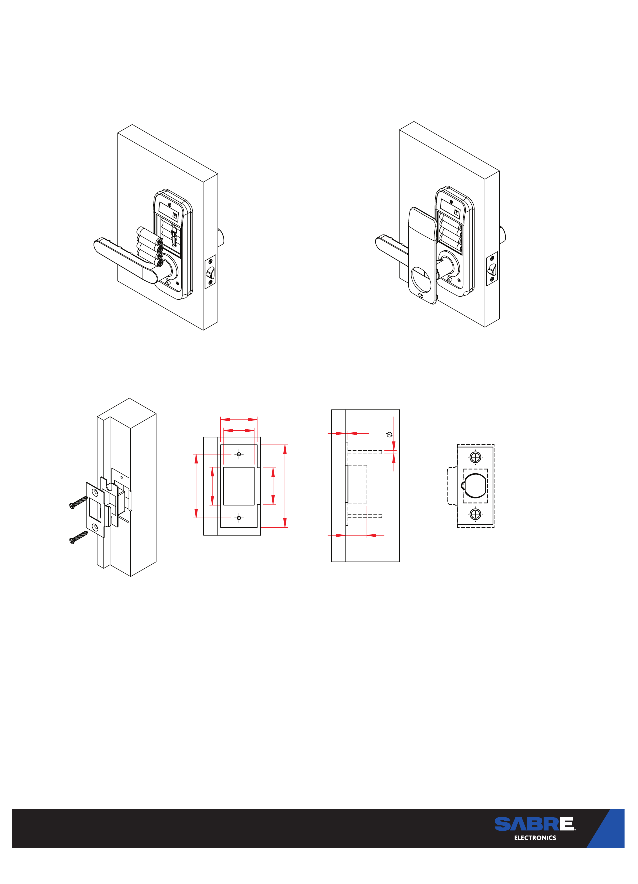
STEP 6 - Dustbox and Striker Plate Installation
27
47
28
22.5
27
61
2
2.5
16
Position striker Plate so latch bolt lock bar is
depressed when latch is engaged in Strike Plate
STEP 5 - Battery and Cover Installation
Internal Lever - Install Batteries Internal Lever - Installation
• Insert batteries with positive and negative
poles as marked on the battery casing
• Loop internal lever cover over lever handle and press into
internal lever
8
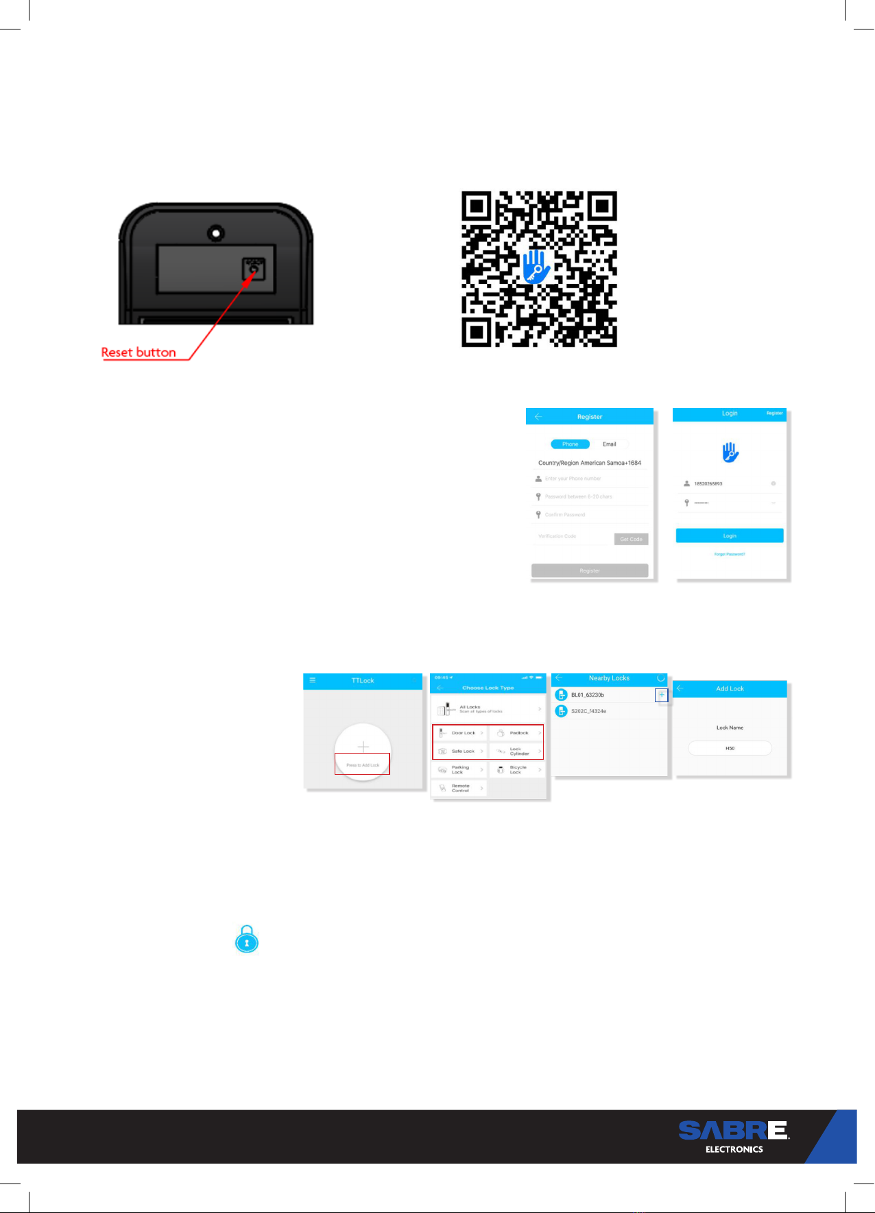
STEP 7 - System Initialisation
Open the cover plate of the front panel, long press
the “Reset” button on the back panel for 5s, press
“000#”, and the initialization is complete
Use the QR code to download the TTLock App. For iOS
and android phones and other devices.
OPERATION
STEP 8 - Registration
1. Please scan the QR code to download the app
2. You can also search for TTLock in the APP store (Google Play) to download
3. Register a new account (phone number or email) or login with an existing
account.
4. Touch the lock screen to light, click “+ Add Lock”
5. The lock nearby will appear on the phone screen, Click “+”
6. Re-name the lock
7. The lock added successfully
STEP 9 - Connect to your phone
TTlock users can register the account by mobile phone and Email which
currently support 200 countries and regions on the world. The verification
code will be sent to user’s mobile phone or email, and the registration will be
successful after the verification.
TTLock supports multiple types of
lock devices. The lock needs to be
added by the app after entering the
add mode. Generally, a lock that has
not been added, as long as the lock
keyboard is touched, it will enter the
add mode. The default password is
123456 if not added by the phone.
Make sure there is no problem with Bluetooth communication. After connecting the phone to the
door lock as above, Click “ “ to unlock. (the phone is within 5 meters from the door lock).
STEP 10 - Add locks
STEP 11 - User Management
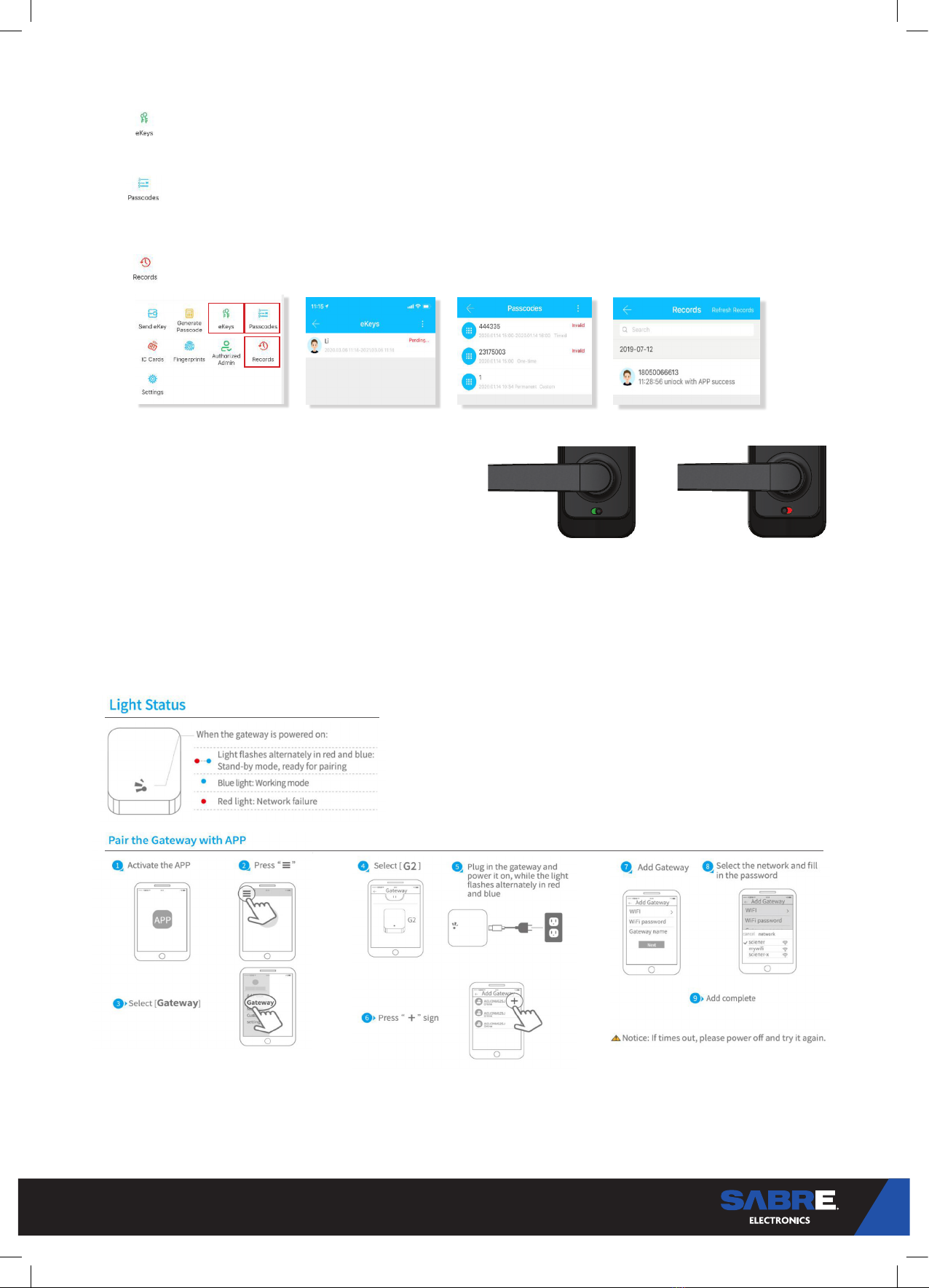
Bluetooth management

9
Passcodes are also a way to unlock. After entering the passcode on the locked keyboard, press the # key to unlock door.
Passcodes are divided into permanent, time-limited, single, clear, cycle, and custom. (You can share the Passcode to other user
via WeChat, SMS, Email, Messenger, WhatsApp).
Setting Passcode
Click on the “ “ as shown below, you can send the eKey to other users of TTlock to authorize the unlock (the receiver must
be download the APP and set up an account)
→Select e-key format (Timed, permanent, One-time, Recurring)
→Enter recipient’s account of TTlock,set the name and eective time of the eKey, Can choose to allow remote unlocking or
disallowing, authorized administrator or not authorized, as shown below
→Send
→The recipient’s account has Bluetooth unlock permission
Supports opening doors through various IC cards. Before an IC card is used to open the door, it needs to be added first. The
adding process needs to be performed by the app beside the lock. The validity period of the IC can be set, it can be permanent,
or it can be limited in time.
Send e-Key
Add card
The premise that a fingerprint can be used to open a door is that it needs to be added first. The adding process needs to be
performed by the APP beside the lock. The fingerprint expiration data can be set, it can be permanent, or it can be limited. After
setting ,you can modify its validity period.
Add fingerprint
10
Click “ “ The manager can delete ekey, reset ekey, send and adjust the ekey, meanwhile he can search the lock record.
Click “ “ All generated passwords can be viewed and managed in the password management module. This includes a
password change, password deletion, password reset, and password unlock record.
e-Key management
Passcode management
Click “ “ you can query your unlock record as shown below
Unlock records
1. If you want to have the Electronic Locking function,
first turn on “privacy lock” on the app
2. When the button is in the red state, it is in the
locked state and can only be unlocked through the
administrator app or mechanical key.
STEP 12 - Privacy Function
LockedUnlocked
Add Gateway
The TT lock is directly connected via Bluetooth, that is why it is not attacked by the network. The gateway is a bridge between
smart locks and home WIFI networks. Through the gateway, the user can remotely view and calibrate the lock clock, read the
unlock record. Meanwhile, it can remotely delete and modify the password.
STEP 13 - Gateway management (Optional)
Manual
After a short period of time, you can see which locks are in their coverage in the app. Once the lock is bound to the gateway,
the lock can be managed through the gateway.
Other manuals for DL700
1
Table of contents
Other Sabre Lock manuals


