SachsenRad E-Racing Bike R8 Flex II User manual

User Manual
with E-Bike pass and maintenance log
SachsenRad E-Racing Bike R8
Flex II
Product number: BB12114 / BB12115

Inhalt
VIDEO INSTRUCTIONS 4
E-BIKE ID / BIKE PASS 5
1. UNPACKING AND ASSEMBLY INSTRUCTIONS 6
2. ASSEMBLY 7
2.1 Before assembly 7
2.2 Required tools 8
2.3 Installing the front wheel 8
2.4 Fitting the handle bar 9
2.5 Aligning the steering head bearing and stem 10
2.6 Installing the pedals 10
2.7 Fitting the saddle 11
2.8 Adjusting the saddle height 12
2.9 About the brake settings 12
2.10 Note on chain tension 12
2.11 Lighting 12
2.12 Removing and inserting the battery pack 13
2.13 The suspension fork 14
3. OPERATION AND FUNCTIONS 14
3.2 Braking with the E-Bike 14
3.3 The control display 15
4. E-BIKE Battery 18
4.1 Battery - charge level indicator 18
4.2 Battery use, safe storage and handling 18
4.3 After use 19
4.4 Charging 19
4.5 Factors inuencing the range 20
4.6 Range optimisation 20
5. BEFORE YOUR FIRST RIDE 20
6. MAINTENANCE 21
6.1 Wheels 22
6.2 Chain 22
6.3 Tyres 22
6.4 E-Bike rear wheel hub motor 23
6.5 Brake system 23
7. SAFETY INSTRUCTION 23
8. SERVICE BOOKLET 24
9. F.A.Q. - Frequently asked questions 25
10. DATA SHEET 27
11. DECLARATION OF CONFORMITY 27
12. DISPOSAL 27
13. IMPRINT 28
14. WARRANTY 28
15. RETURN RECEIPT 31

3
Thank you for purchasing our product!
Please read these instructions carefully.
Cycling is a natural part of a modern, health-conscious lifestyle. People are travelling longer and longer and the
roads for riding are more complicated. Due to the physical differences, riding habits and handling characteristics
of each cyclist, especially when riding uphill or long distances, cycling can be very strenuous. Our e-bike was
specially designed to solve these problems!
This e-bike is a combination of a high-quality lithium battery and a high-end bicycle. Go faster and further with
more fun: It is the ideal companion for your tness programme, for leisure time and for the ways that need to
be done.
Important notes
This manual contains important safety, performance and service information.
Please ensure that you have read and understood the following warnings and precautions before using the pro-
duct for the rst time.
If you lend your e-bike to another person, ask them to read this manual to minimise the chance of accidents.
WARNING: Wear a suitable and qualied helmet while riding and wear uorescent or reective clothing at night.
WARNING: Your existing insurance policies may not cover everything that could occur when using an e-bike.
Please consult your insurance company or your insurance broker. Note: This manual does not cover all possible
complications that may occur while riding. Please also read the F.A.Q. to solve any problems with the e-bike.
For more information, please contact your dealer. Please also contact your dealer or nd a professional service
technician if repair or maintenance is required. Please observe all warnings in this manual, read and understand
the contents before using your bike.
WARNING: Warnings indicate that signicant property damage, serious injury or death to you or others may
occur. Please be sure to follow the instructions.

4
VIDEO INSTRUCTIONS
Under the following link you will nd video instructions for assembly on YouTube
https://www.youtube.com/watch?v=Y1pG6k6E--Y
In case of a return, please contact our customer service rst. In the case of a return shipment, please ensure that
it is dismantled properly. We also have a short video online for you:
https://www.youtube.com/watch?v=zJ2FOVUJSYw
Under the following link you will nd a video tutorial on how to adjust the brake system
https://youtu.be/Tcc8BmI8occ
NOTE ON THE PICTURES
Pictures and graphics in the manual may differ from your actual product as the R6 is manufactured in several
versions. The pictures are intended as supplements to the text and for better under-standing.

5
E-BIKE ID / BIKE PASS
PLEASE COMPLETE THE FOLLOWING E-BIKE PASSPORT, IN MINIMAL FORM, CAREFULLY IN YOUR OWN
INTEREST!
* THE FRAME NO. IS LOCATED ON THE FORK SHAFT TUBE (BEHIND THE HEADLIGHT)
FRAME NO.*
MODEL
TYPE
ENGINE (REAR/CENTER)
SIZE (IN INCHES)
COLOR
GEAR SHIFT
SPECIAL
EQUIPMENT
OWNER
SELLER
PURCHASE DATE

6
1. UNPACKING AND ASSEMBLY INSTRUCTIONS
Tip: Your e-bike is slightly heavier than a normal bike. It is best if two people lift it out of the box.
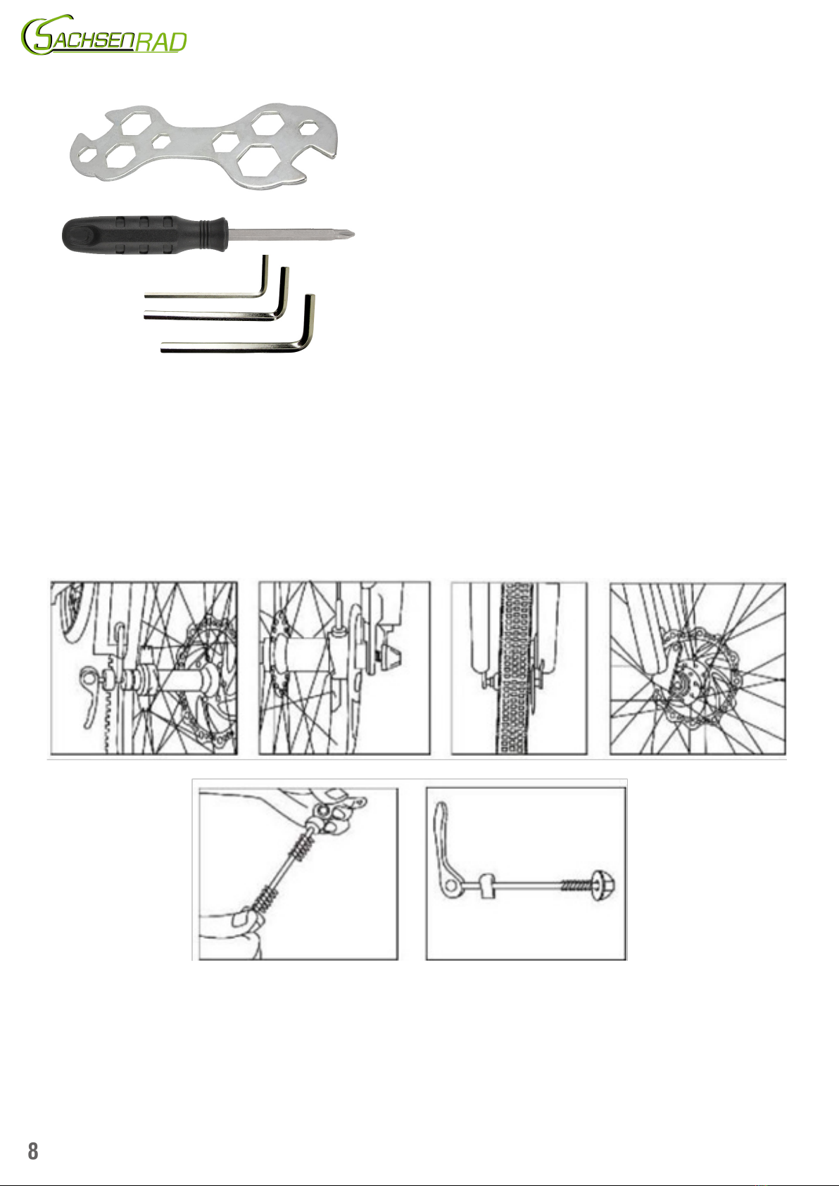
Required tools and aids (recommendation)
- Tool kit (supplied, see 2.2)
- Blanket or old carpet (to prevent the oor or the e-bike from being scratched during assembly)
Please read the following instructions carefully before unpacking and assembling your e-bike and follow the
recommended sequence.
1. Carefully open the packaging box (to avoid injury, please wear gloves).
2. Carefully remove the bike from the box, preferably in pairs.
3. Place the bike on a blanket to avoid scratching the oor and the bike.
4. Take all the parts out of the large box, including the accessories box.
5. Carefully cut the various cable ties. By doing so, do not accidentally damage the bike, paint or tyres or lose
accessories.
6. Remove all protective material.
7. Remove the e-bike battery from the packaging or from the e-bike battery sled and charge it for at least 10-12
hours rst. Please read sections 5.2 and 5.3.
(Tip: The battery must be charged for at least 12 hours before rst use. Please read section 5.2 and section 5.3. )
Remarks: Upgrading with accessories, attachments or tampering with the control units.
WARNING: If you need to upgrade parts or add accessories, beware of the following: Before attaching parts or
accessories, make sure that the specications and dimensions match. Please check with your dealer if necessa-
ry. Parts with different specications can be tted but there is a major safety risk.
WARNING: Incorrect installation and use of parts not supplied with the e-bike and improper modications to the
original condition of the e-bike may result in signicant property damage or the voiding of any warranty or gua-
rantee claims. Even accidents, serious injuries or death can be the result. If you wish to upgrade or add further
parts or accessories, please contact your dealer or a suitable expert. They can give you information about this.
WARNING! If you replace parts of the e-bike, upgrade parts or add accessories, please note that such changes
may not have the same safety qualications, so there is a certain safety risk.

7
Designation of the e-bike parts
1. Saddle
2. Seat post
3. Quick release saddle
4. Rear brake
5. Front wheel / tyre
6. Front brake
7. Pedals and chainring
8. Suspension fork
9. Battery slides
10. Drive chain
11. Rear wheel / tyre
12. Sprocket cassette
13. Motor
14. Battery charging connection
15. Bicycle handle bar
16. Left hand brake lever (rear brake control)
17. Right brake lever (front brake control)
18. Front and back light
2. ASSEMBLY
2.1 Before assembly
WARNING: Incorrect assembly of your e-bike can cause signicant damage to the bike and even personal injury.
If you are not sure whether your assembly is correct, please contact your dealer.
WARNING: The motor, controls, sensors, battery and various cables on your bike must not be used for other
purposes. Do not disassemble or modify [adjust] these parts as this may cause serious damage to them, voiding
the warranty. It may also harm your personal safety. If you need assistance, please contact your dealer.

8
2.2 Required tools
3x allen key
1x multi-open-end spanner
1x screwdriver
OT INCLUDED IN DELIVERY:
Air pump with car valve
Please bring the tyre pressure of the front and rear wheel to at least 2.8 bar with the help of an air pump
BEFORE THE FIRST RIDE. Attention: Tire pressure should not be higher than 3.5 bar!
Note: For transport reasons, we can only deliver the e-bike with very low tyre pressure. Do not ride without rst
inating the tyres!
2.3 Installing the front wheel
Remove the black plastic covers on the left and right of the front wheel that were used to secure it for transport.
Carefully loosen the cable tie on the spoke with which your quick-release axle is attached.
Unscrew the nut of the quick release axle including a spring, put the quick release axle through the axle of the
front wheel.
Now carefully insert the front wheel between the legs of the suspension fork. Pay attention to the direction of

9
the wheel. The brake disc must be on the side of the brake caliper. Carefully insert the disc into the brake calliper
parallel to the wheel in that manner that no damage to the brake or brake disc is inicted.
When everything is set correctly, slide the spring back onto the axle and carefully screw the grip nut onto your
front axle until the quick release can be ipped over hand-tight, thus holding the wheel rmly in the mount.
Now let the wheel turn by hand and check that it sits and runs correctly. Check and test the front brake. The ins-
tructions for adjusting the brakes can be found under section 2.5. If everything works, your front wheel should
now be correctly mounted.
2.4 Fitting the handle bar
Fig.1 Fig. 2 Fig. 3
Now you shave to mount the handlebar and then readjust the steering head bearing. First loosen the four bolts
of the stem (Fig.1).
NOTE: The stem is designed differently on some versions.
Now place the handlebars in the stem shell (please note the direction and run of the cables and Bowden cables)
and screw the stem back on as shown in Fig. 2. Before doing so, align the handlebar centrally with the stem
and tighten the four hexagonal bolts crosswise using the tool supplied. Tighten the bolts evenly and carefully.
ADJUSTING THE TILT OF THE HANDLEBAR: First loosen the clamping spindle screws of the handlebar sleeve
(Fig. 1) with the appropriate hexagon socket spanner. Adjust the angle of inclination of the handlebar by turning
the handlebar forwards or backwards around its own axis by hand. Tighten the clamping spindle screws again.

10
2.5 Aligning the steering head bearing and stem
Note: This step may differ for your model and may not be necessary because it is already pre-assembled.
Note: The handlebars have not yet been mounted in the illustration, this is for the clarity of the graphic.
Please stick to the assembly sequence described.
Now that the handlebars are installed, you still have to turn the stem 180 degrees so that the suspension fork and
handlebars are in the correct position. To do this, rst detach the rubber screw cover (C) and loosen the underly-
ing screw (C) with the appropriate tool. Open the horizontal ones, stem screws ((A) and (B) in the illustration) so
that the steering head bearing can move freely when turning and tightening. Now align the handlebars with the
stem at a 90-degree angle to the suspension fork off by rotating it by 180° (orientate yourself on the cables and
Bowden cables whether to the left or right). The arrows (1) and (2) describe the directions of the stem and the
suspension fork. On the left The picture shows the condition as delivered and the one on the right shows the nal
alignment of the assembly. When everything is correctly aligned, tighten the single cap screw (C) until the steer-
ing head bearing has no more play but still easy to move. Then you can unscrew the two horizontal screws of
the handlebar stem once from the left (A) and once from the right (B) until everything forms a unit. Finally stuck
Put the rubber screw cover (C) back on the hex screw from above.
2.6 Installing the pedals
1. Please fasten your bicycle. It is best if two people hold it so that the chain and crank can turn smoothly.
2. Take the pedals out of the packaging and sort them. „R“ stands for the right foot, the „L“ is the left foot.
3. Align the foot thread with the mounting hole on the crank, tighten the right pedal clockwise and the left pedal
anticlockwise.

11
4. Use a 15 mm open-ended spanner to lock the foot.
WARNING: Improper installation of the pedal can pose a serious safety hazard resulting in signicant property
damage, serious injury or death. Please check that the pedals are secure before each use.
2.7 Fitting the saddle
1. Make sure that the quick-release of the seat post is open (picture A).
2. Insert the seat post into the seat post bracket of the frame (picture B).
3. Press the quick-release lever onto the frame and close it.
Please make sure that the lever is locked (picture C). Otherwise injuries may occur
Picture A Picture B Picture C
Tip: Please adjust the nut on the opposite side of the lever to adjust the tightening force of the lever.
WARNING: Do not pull out the seat post more than the marking of the minimum insertion depth. The marking
must not be visible! Risk of breakage and accident! No warranty in case of disregard !

12
2.8 Adjusting the saddle height
1. The height of the saddle can be adjusted with the quick-release on the saddle rail. You only need to release
the quick-release lever to freely select the height of the saddle. After you have adjusted the desired height, lock
the quick-release lever again and the adjustment is complete.
2. After the adjustment, make sure that the quick-release lever of the seat post is well locked. The seat post must
not slip.
WARNING: Incorrect installation of the seat post may result in serious injury or death. It is strictly forbidden to
raise the height of the seat post above the safety line.
2.9 About the brake settings
If you are not satised with your brakes, please contact your dealer and ask for the intervention of a professional
technician.
2.10 Note on chain tension
Not after the rst few rides, but after a certain period of use, the chain may be worn out due to transmission
strength and can be properly adjusted by using a tensioning screw to hold the chain in place. The chain should
be set on the smallest tooth of the ywheel. Turn the rear transmission tensioning screw (see g. A) clockwise
with a screwdriver. The chain should not sag. Also make sure that the chain is sufciently greased and clean.
2.11 Lighting
NOTE: If front and rear lights and bell are included in the accessory pack, they must yet be tted.
Rear light
You will nd the battery-powered rear light in the accessory box. Attach it to the seat post below the saddle using
the screwdriver provided. If the clamp of the rear light mount is too loose, use the rubber strip provided. Before
using the rear light for the rst time, remove the battery protection strip.
Front light
If you do not nd your front light already adjusted to the front of the bike, unpack the light from the accessory
box and install it using the hexagonal bolt and nut supplied. You will nd the necessary tools in the tool bag in the

13
accessory box. Connect the plug of the lamp to the plug on the e-bike. Pay attention to the arrows on the side.
2.12 Removing and inserting the battery pack
removing the battery inserting the battery
removing the battery
To remove the battery, insert the supplied key into the lock and turn it slightly to the right. Now the battery should
come out of the lock a little bit. Then you can remove the battery from the battery compartment. Be careful not
to damage the paint of the e-bike frame.
inserting the battery
First insert the lower part of the battery into the battery compartment. Be careful not to damage the paint of the
e-bike frame. The battery should now slide into the battery slot almost by itself. Press the battery lightly until it
clicks into place and is thus rmly xed in the battery bay.

14
2.13 The suspension fork
You can lock your suspension fork (e.g. for longer rides on asphalt roads without bumps) to save energy. To do
this, set the red lever (A) to ʺlockʺwith the suspension fork unloaded when stationary. To set your suspension
fork back to suspension mode, the red lever must be set to ʺunlockʺagain.
On the other side of the suspension fork you have the option to set the suspension a little softer or harder, please
look at the labeling of the gray lever (B). By turning to the right you adjust the fork a little harder (+), by turning to
the left a little softer (-). Only adjust both settings when the bike is stationary and without loading the suspension
fork, never while riding.
3. OPERATION AND FUNCTIONS
Please read this section carefully. Before using the device for the rst time, please contact your dealer to learn
more about the features of your electric bike.
1. Put on your helmet and choose a quiet place away from cars, other bicycles, obstacles or risky
environmental conditions.
2. Make sure the power switch is in the ʺoffʺposition and then raise your bike stand.
3. Ride your electric bike for a test ride without motor assistance and adjust everything to suit you.
4. Press the switch in the centre of the display control unit for at least two seconds to set your motor to
standby.
NOTE: Please keep the battery main switch in the 0 position until you are safely on the bike.
WARNING: Do not sit on your bike with the bike stand unfolded as this may cause damage to the vehicle and
personal injury.
Nothing working?
Please refer to section 9 for troubleshooting:
F.A.Q. - Frequently asked questions about problems and their solutions
3.2 Braking with the E-Bike
TIP: When you apply the brakes, the motor is automatically switched off, which is a standard safety setting.
TIP: There is a sensor in the brake lever. When you apply the brake, the motor is automatically switched off. So
do not press on the brake handle when you want the motor to work. Try the brakes at low speed. The brake hand-

15
le of the left hand corresponds to the brake of the rear wheel. The brake handle of the right hand corresponds to
the front wheel brake. Never brake hard. Squeeze both brakes together.
WARNING: If you suddenly and harshly engage the front brakes, you will roll over. Please do not set your brakes
too hard to prevent wheel lock and accidents. Check the sensitivity and braking force of the brakes before each
ride.
3.3 The control display
Intelligent control display for electric bikes:
Model: KD 21C
Specications
• 24V / 36V / 48V power supply
• rated current: 10mA
• maximum working current: 30mA
• quiescent current when switched off: <1 µA
• working temperature: -20 - 60 ° C.
Control display dimensions (in mm)
Functions of the control display
•intelligent battery indicator
•engine power output
•assistance level indicator
•speed display
(incl. current driving speed, maximum speed and average speed)
•restore default settings
•total distance and driving distance
•the push assist function
• time display for single trip
•illumination on/off
• error code display

16
Installation instructions
The control display is mounted on the left side of the handlebar. Adjust the angle for a good screen view. Switch
off the power beforehand.
General operation
Switching the e-bike control display on and off
To switch on the control display, press and hold the menu button for 2 seconds. If you press and hold the Menu
button again for 2 seconds, the e-bike system will turn off. If you park the e-bike for longer than 10 minutes, the
system will automatically switch off.
Error code denition
If improper operation by the user occurs (e.g. excessive pressing of the menu /+ or - button), the user can switch
off the display and restart it. If the e-bike is not moved for about 10 minutes, the control display will automati-
cally turn off.
Operation and functions
Speed levels
When the control display is turned on, the speed level is 0. There are 5 speed levels. At speed level 0, the e-bi-
ke runs without speed assistance. At the minimum power level 1, the driving assistance starts and you get the
maximum power at level 5. You can change the speed level using the + and - button.
Switching the lighting on/off
To turn on the display back light and the front light of the e-bike, press and hold the + button for 2 seconds. If
you press and hold the + button again for 2 seconds, the back light and front light will turn off.
Restoring the default settings
DEF stands for Restore Default Settings. The default value is N. To revert to the default settings, press and hold
the Up (+) and Menu buttons for 2 seconds, then press the +/ button to select Y or N. N means that the default
settings will not be restored. Y means that the default settings will be restored. If you want to select Y, press and
hold the MODE button for 2 seconds to restore the default settings. The display will show DEF-00 at the same
time and then return to the general display status.
Error code display
The components of the e-bike system are continuously and automatically monitored. As soon as an error is
detected, the control display shows you an error code (see error code list).

17
If an error code is displayed, have the display checked and repaired if necessary. Please contact the manufactu-
rer or a bicycle dealer near you.
INDEX OF ERROR MESSAGES (appear on the control display)
Error number Error code denition
21 current uctuation
22 throttle error
23 motor fault
24 faulty signals from motor
25 brake fault
30 Communication error
Quality assurance and warranty
The warranty is valid for 24 months, from the date of purchase of the e-bike and only when used properly.
The following cases are not covered by the warranty:
1. the display is torn off.
2. the damage of the display is caused by incorrect installation or use.
3. the housing of the control display has been damaged after the purchase of the e-bike through the fault of a
third party after the purchase of the E-bike.
4. the cable of the display is broken.
5. the warranty period has been exceeded.
Warning
1. use the display with care. Please do not open the housing when the control display is switched on.
2.Avoid hitting the display with objects.
3.Contact the manufacturer if the display does not work properly.
4.This manual is a universal version for display - KD21C. The specication may differ to the software.
Attention!
It is strictly forbidden to open the display controller and motor controller privately and change the components
and circuits in the controller. Do not overload or operate the motor over a long distance or a very steep incline.
Do not change the mounting position of the controller. It is strictly forbidden to attach other things to the cont-
roller housing that will affect heat dissipation.
Warning: Do not clean the battery sled with integrated controller with liquids when cleaning the bike. The cont-
roller should always be well ventilated.

18
4. E-BIKE Battery
charging port
4.1 Battery - charge level indicator
Press and hold the button of the battery charge
level indicator and you will be shown the current
charge level of your e-bike.
Illumination of the LEDs:
blue ›› fully charged
green ›› medium charge
red ›› low charge
ashing ›› battery needs charging, no operation possible
Always check the remaining battery power. If your battery contains less than one cell (20%), please charge it as
soon as possible.
The motor and battery control will stop automatically to protect the battery and prevent a power failure when the
battery voltage is below a certain level.
Warning: Never use the battery until it is completely discharged, as this will seriously affect the capacity and
charge level of the battery. If the battery stops working, use an appropriate charger to recharge the battery. The
battery can be fully charged in approximately 5 - 6 hours under normal conditions.
Note: If you suddenly encounter a steep incline while riding and your speed drops below 10 km/h, you should
dismount and climb the incline on foot to prevent the chain and motor from being damaged. Otherwise, the mo-
tor may overheat. The battery discharges too quickly at high power and the battery capacity and life are reduced.
4.2 Battery use, safe storage and handling
Battery Usage
Reading and understanding the following points can help you properly use, maintain, and store your battery,
which is very important for improving the performance of your e-bike.
WARNING: Improper removal, repair, use or storage of the battery may void the warranty and may result in
serious consequences. It is strictly prohibited to use the battery of your electric vehicle for other vehicles or de-
vices. Doing so will void the warranty and may result in serious consequences such as re, serious bodily injury
or death. If you have any questions about the use of the battery, please contact your dealer.

19
WARNING: Never short circuit a battery pack intentionally. Doing so may result in an explosion, re, and serious
risk to your health.
Tip: Your battery must be charged for at least 12 hours before using it for the rst time. If your battery is not
used for more than 30 days, continue reading in section 4.6.
4.3 After use
Switch off the control display before dismounting in order to be able to safely lower the bicycle side stand. If
there are any questions regarding the last use of your e-bike, please contact your dealer or a specialist workshop
before the next ride.
4.4 Charging
Please fully charge your battery, as the lithium-ion battery can be severely damaged if fully discharged. Keeping
the battery charged will help to preserve it. Refer to sections 4.5 and 4.6 for details.
NOTE: Please unplug the charger from the wall outlet before connecting the charger‘s power plug to the wall
outlet.
NOTE: If you wish to disconnect a charger from the mains, rst switch off the charging switch.
CAUTION: To avoid damage to the charger, do not tear the charger or subject it to strong impact.
WARNING: Improper use of the charger can result in serious consequences, including re, signicant property
damage, serious injury, or death.
NOTE: Do not place any objects on the battery and charger during charging as this may cause overheating and
serious consequences.
NOTE: Please use your charger indoors as damage caused by improper use is not covered under warranty.
Charging Schedule (Recommendations)
Charging Hours
First three charges 12
Normal charge 4-6
Every ten charges 12
Charge the battery after each use to ensure the longest possible life.
CAUTION: Never charge for more than 12 hours to avoid overcharging.
WARNING: Please use the included charger to charge the battery. If you use a charger other than the original,
the battery will void its warranty and may be damaged, resulting in re, injury or death.
Tip: You can recharge your battery at any time. If you do not charge the battery in time when it is empty, it will
gradually lose its performance and life. With proper use and maintenance, your battery can maintain more than
80% capacity after more than 500 charging cycles, but the decrease of total capacity is inevitable.

20
4.5 Factors inuencing the range
Factors inuencing the range of your e-mobility with the R8
• Age and state of charge of the battery
• Storage/storage location before the trip (depending on temperature)
• Outside temperatures
• Tyre pressure (recommendation: 2.9 - 3.4 bar)
• Weight of rider
• Riding style and choice of assistance level
• Road/ path conditions
• Weather conditions
• Frequent stops and restarts
• Cleanliness and inertness of bearings and all moving parts
4.6 Range optimisation
• Fully charge the battery
• Check tyre pressure 2.9 - 3.4 bar
(recommended depending on body weight, load and route prole)
• Reduce the load
• Do not ride too fast
• Maintain a constant speed
5. BEFORE YOUR FIRST RIDE
This section is to prepare you for your rst ride. Please always wear a safety helmet of the correct size. If you
wish to lend the e-bike to others, please ensure that they wear a safe and appropriate helmet.
Do not take anyone with you on the bike!
Overloading, which can be caused by double occupancy, can have serious consequences resulting in signicant
property damage, serious injury or death.
Compliance with trafc laws and regulations
Please drive on the right-hand side of the road. Observe local laws and regulations!
Reectors
Please keep the reectors clean and bright and please do not remove the reectors.
Check the brakes
Please check the braking distance and braking force before each ride. Please note that the left brake corresponds
to the rear brake and the right brake corresponds to the front brake. Your e-bike is equipped with normal speci-
cations of brake pads. Please check the brake pads every time and ask your dealer about the brake pads. If the
brake pads are worn, please replace them as soon as possible.
Tyre pressure
Usually 2.9 - 3.4 bar (depending on the tyre pressure indicated on the side of the tyre). Your tyres contain inner
tubes. You must inate the inner tubes. Please check the pressure of the tyres before each ride. The tyres gradu-
ally lose pressure, this is normal. If you lose too much air pressure, please inate again. If your tyre pressure is
This manual suits for next models
2
Table of contents
Other SachsenRad Bicycle manuals