SAER Elettropompe MT Series User manual

ELETTROPOMPE
®
GB
Motori elettrici in bassa tensione serie MT I
Low voltage electric motors series MT

ELETTROPOMPE
®
2
Temperatura / Temperature -10°/ + 40°C
Umidità relativa / Relative humidity 60% (@ + 40°C)
Altitudine / Altitude max 1.000 m s.l.m.
TAB. I - Condizioni ambientali di funzionamento
Environmental conditions of working
TAB. II - Valori di rumorosità
Noise levels
≤4
5,5 ÷18,5
22 ÷45
55 ÷90
> 90
Potenza nominale motore
Rated power of motor
1450 1/min 2900 1/min 3600 1/min
≤54 ≤73 ≤77
≤66 ≤75 ≤80
≤70 ≤77 ≤83
≤75 ≤84 ≤90
> 90
Livello pressione sonora
Noise level
Kw dBA
TAB. III - Forme costruttive e posizioni ammesse di installazione per versioni standard
Constructive forms and allowed mounting arrangements for standard versions
IM B3 (IM 1001) IM V5 (IM 1011) IM B6 (IM 1051) IM B7 (IM 1061) IM B8 (IM 1071)
Posizione base
Main mounting
arrangement
Altre posizioni ammesse
Different allowed mounting arrangement
IM B5 (IM 3001) IM V1 (IM 3011)
IM B35 (IM 2101)
IM B14 (IM 3601) IM V18 (IM 3611)

ELETTROPOMPE
®
3
TAB. IV - Coppie serraggio per bulloni di fissaggio dei piedi
Tightening torque for foot fixing bolts
56M M5 4
63M M6 7
71M M6 7
80M M8 18
90 (S; L) M8 18
100L M10 30
112M M10 30
132 (S; L) M10 30
160 (M; L) M12 60
180 (M; L) M12 60
200 (M; L) M16 140 (Alluminium frame) / 210 (Cast iron frame)
225 (S; M) M16 210
250 (S; M) M20 270
280 (S; M) M20 270
315 (S;M) M24 470
Grandezza carcassa
Frame size Coppia consigliata
Suggested torque
Bullone o vite
Bolt or screw
TAB. V - Coppie serraggio per collegamento in morsettiera
Tightening torque for connection in teminal board TAB. VI - Coppie di serraggio per altre viti (conduttori di terra,
copriventola ecc…)
Tightening torque for other screws (ground cable,
fancover, others)
Perno
Stud
Coppia consigliata
Suggested torque
Nm
M4 2,0
M5 4,5
M6 7,5
M8 15,0
M10 25,0
M12 45,0
M14 50,0
Vite
Screw
Coppia consigliata
Suggested torque
Nm
M4 2
M5 4
M6 7
M8 18
M10 30
M12 60
M16 140
TAB. VII - Motori con altezza d'asse fino a 180: intervalli di sostituzione dei cuscinetti prelubrifcati a vita
(ingrassaggio permanente) - principio L10
Motors with shaft height up to 180: terms of replacements for pre-lubricated bearings for life
(permanent greasing) - principle L10
1500 40 40.000 h 20.000 h
1800 40 32.000 h 16.000 h
3000 40 20.000 h 10.000 h
3600 40 16.000 h 8.000 h
Velocità di rotazione max.
Max rotatational speed
1/min (rpm)
Intervallo di sostituzione
Terms of replacement
Temperatura ambiente max.
Max ambient temperature
°COV
O: funzionamento in orizzontale / Horizontal mounting - V: funzionamento in verticale / Vertical mounting

ELETTROPOMPE
®
4
TAB. VIII - Motori dotati di ingrassatori: intervalli di rilubrifcazione - principio L10
Motors with greasers: re-lubrication terms - principle L10
Velocità di rotazione max.
Max rotation speed
1/min (rpm)
Intervallo di rilubrificazione
Re-lubrication terms
Potenza nominale
Rated power
kW
FIG. 2 SCHEMI DI COLLEGAMENTO / CONNECTION DIAGRAMS
a) monofase per alimentazione a tensione unica senza condensatore
single-phase for a single voltage power supply without condenser
Temperatura ambiente max.
Max ambient temperature
°COV
1500
1800
3000
3600
40
40
40
40
≤37
45 ÷90
110 ÷132
> 132
≤37
45 ÷90
110 ÷132
> 132
≤37
45 ÷90
110 ÷132
> 132
≤37
45 ÷90
110 ÷132
> 132
6.000 h 3.000 h
4.000 h 2.000 h
3.000 h 1.500 h
2.500 h 1.250 h
4.800 h 2.400 h
3.200 h 1.600 h
2.400 h 1.200 h
2.000 h 1.000 h
3.000 h 1.500 h
2.000 h 1.000 h
1.500 h 750 h
1.250 h 625 h
2.400 h 1.200 h
1.600 h 800 h
1.200 h 600 h
1.000 h 500 h
b) monofase per alimentazione a tensione unica con condensatore
single-phase for a single voltage power supply with condenser
c) monofase per alimentazione a tensione unica con condensatore per potenze 3 e 4 Kw
single-phase for single voltage power supply with condenser for power of 3 and 4 kW
d) monofase per alimentazione a due possibili tensioni con condensatore (d1= tensione bassa; d2= tensione alta),
trifase per alimentazione a due possibili tensioni (d3=tensione bassa; d4= tensione alta)
single-phase for power supply with two possible voltages with condenser (d1= low voltage; d2= high voltage);
three-phase for power supply with two possible voltages (d3= low voltage; d4= high voltage)
FIG. 1 TARGHE IDENTIFICATIVE / NAME PLATES
Motori grandezza > 200
Frame size > 200 Motori grandezza fino a 200
Frame size up to 200
a
L
N
b
LN
U1 V1 W1
c
L
U2 V2
V/2
V/1
U1 V1
1L
2
d2
L
U2 V2V/2
V/1U1 V1
1L
2
d1
L
U2 V2
V/2
V/1
U1 V1
1L
2
d3
L
U2 V2V/2
V/1U1 V1
1L
2
L
2
d4
L
U2 V2V/2
V/1U1 V1
1L
2
L
2

ELETTROPOMPE
®
5
Il mancato rispetto comporta il
rischio di danni a persone e/o cose Il mancato rispetto comporta il
rischio di scosse elettriche Il mancato rispetto comporta il rischio
di danni al motore o all'impianto
1. GENERALITÀ
Prima di eseguire qualsiasi operazione, leggere attentamente il presente manuale. Il costruttore declina ogni responsabilità per le conseguenze
derivanti dalla mancata osservazione delle indicazioni riportate o da uso improprio del prodotto. Per tutte le situazioni o gli usi non contemplati
in questo manuale, contattare l'assistenza tecnica.
Il trasporto, l'installazione, il collegamento, la messa in servizio, la conduzione e l' eventuale manutenzione o messa fuori servizio,
devono essere eseguiti da personale esperto e qualificato e nel rispetto delle norme di sicurezza generali e locali vigenti. Per personale
tecnico qualificato vale la definizione riportata dalla norma IEC 60364.
E' vietato manomettere il prodotto.
L'utente è responsabile di pericoli o incidenti nei confronti di altre persone o loro proprietà.
Utilizzare il motore solo per gli scopi descritti nel paragrafo 4. Ogni altro utilizzo può essere causa di infortuni.
Prima di effettuare qualsiasi operazione, scollegare i cavi elettrici di alimentazione. Non toccare il motore quando è in funzione.
Il motore è un dispositivo da integrarsi con altri dispositivi al fine di formare una macchina per applicazioni specifiche. La messa in
servizio non è consentita finché non è stata accertata la conformità dell'assieme finale (macchina) alla Direttiva Macchine.
2. SICUREZZA / AVVERTENZE ANTINFORTUNISTICHE
3. TRASPORTO / MOVIMENTAZIONE E IMMAGAZZINAGGIO INTERMEDIO
I motori devono essere sollevati mediante idoneo dispositivo di sollevamento. Utilizzare gli appositi golfari: questi sono dimensionati per sopportare
solo il peso dei motori.
Verificare lo stato dei golfari ed il loro corretto serraggio prima di procedere al sollevamento del motore
Movimentare i motori con i dovuti mezzi di sollevamento, eventuali urti o cadute possono danneggiarli anche senza danni esteriori o
arrecare danni a persone o cose.
Scollegare i mezzi e i dispositivi di sollevamento prima della messa in funzione.
Condizioni di immagazzinamento: immagazzinare al coperto, in un luogo asciutto, privo di polvere, gelo e vibrazioni.
T minima immagazzinamento = -20°C
Proteggere le superficie metalliche esposte (estremità d'albero, flangie) con mezzi adeguati per prevenirne la corrosione.
4. CARATTERISTICHE TECNICHE E IMPIEGO
DESCRIZIONE PRODOTTO - Versioni standard
Motori trifase bassa tensione: motori asincroni, raffreddati da ventole, totalmente chiusi, con rotori a gabbia di scoiattolo(TEFC). Albero con
sporgenza cilindrica e attacco con chiavetta.
Classe di raffreddamento: IC 411 secondo IEC 60034-6
I motori normalizzati hanno dimensioni in accordo a IEC 60072-1
Classe di isolamento: motori fino a grandezza costruttiva 71: classe B, per grandezze costruttive superiori: classe F.
Grado di protezione: motori fino a grandezza costruttiva 71: IP44, per grandezze costruttive superiori: IP55
Rumorosità: vedere TAB.II
Fino a 4 kW i motori sono fornibili anche in versione monofase con avviamento tramite condensatore elettrolitico.
Tipo di bilanciatura dell'albero: se non diversamente indicato, gli alberi sono bilanciati con mezza chiavetta.
IMPIEGO
Motori per uso industriale, conformi a IEC 60034-1. Le forme costruttive e le possibili posizioni di installazione sono rappresentate in TAB.III
I dati identificativi e i dati tecnici caratteristici del motore sono riportati sulla targhetta (fig. 1)
Non utilizzare i motori in ambienti potenzialmente esplosivi.
Variazioni di tensione e di frequenza durante il funzionamento: rispettare zona A secondo IEC 60034-1 (tensione ±5%; frequenza ±2%).
I
ATTENZIONE
ATTENZIONE
ATTENZIONE

ELETTROPOMPE
®
I
6
5. INSTALLAZIONE
Prima di effettuare qualsiasi operazione, togliere la corrente e assicurarsi che non possa essere ripristinata.
- Verifiche preliminari
√Verificare che i dati indicati sulla targa, ed in particolare potenza, frequenza, tensione, corrente assorbita, siano compatibili con le caratteristiche
della linea elettrica o del generatore di corrente disponibili.
√Verificare che il grado di protezione e di isolamento indicati sulla targa siano compatibili con le condizioni ambientali.
√Verificare che il motore non sia mai esposto alle intemperie.
√Verificare le condizioni ambientali: i motori SAER possono essere installati in locali chiusi o comunque protetti, con temperatura ambiente
max di +40 °C, in atmosfera non esplosiva.
In caso di utilizzo in condizioni ambientali con temperatura maggiore di +40 °C o altitudine superiore a 1.000 m sul livello del mare contattare
l'Assistenza Tecnica.
√Verificare che l'albero del motore ruoti liberamente a mano, senza rumori o strisciamenti.
Ω
Verifica della resistenza di isolamento
√Verificare la resistenza di isolamento: la resistenza di isolamento di un avvolgimento nuovo deve essere superiore a 10 MΩ alla temperatura
ambiente di 20°C con tensione di prova di 500 V cc. Valori più elevati di temperatura ambiente riducono i valori di resistenza di isolamento
(il valore si dimezza ogni 10°C di aumento di temperatura). Scollegare i cavi di alimentazione prima di eseguire la verifica. Eseguire la verifica
prima del primo avviamento e dopo lunghi periodi di inattività.
Non toccare il motore durante e dopo la misura della resistenza di isolamento. Dopo la misura, scaricare l'avvolgimento per evitare
rischi di shock elettrico.
Stato di lubrificazione dei cuscinetti
Verificare il corretto stato di lubrificazione dei cuscinetti secondo quanto indicato nel paragrafo “Manutenzione”
Fondazioni
√Accertarsi che il piano di appoggio del motore sia ben consolidato, regolare (in modo che tutti i piedi appoggino) e che la portata di tale piano
sia adeguata al peso. La planarità del piano di appoggio dei piedi non deve superare ±0,1mm.
√Verificare che lo spazio circostante sia sufficiente a garantire la ventilazione e la possibilità di movimento per gli eventuali interventi di
manutenzione.
√Verificare che il punto e la superficie di fissaggio impediscano l'eventuale trasmissione di vibrazioni alle strutture circostanti.
√Verificare che le fondazioni in calcestruzzo abbiano resistenza adeguata e siano conformi alle norme di pertinenza.
I motori dotati di piedi devono essere fissati tramite i piedi della base e dotati di appoggi adeguati.
Le dimensioni dei bulloni di fissaggio alle fondazioni e di collegamento della flangia alla macchina condotta, devono essere in accordo a EN
50347. Fare riferimento inoltre a TAB. IV per le coppie di serraggio raccomandate.
Elementi condotti e allineamento
Gli elementi condotti (giunti, pulegge, ventole ecc…) devono essere accoppiati solo tramite dispositivi idonei e devono avere un grado
di equilibratura idoneo. In alcuni casi può essere necessario eseguire un'equilibratura della macchina completa (vedere ISO 10816)
√Verificare la pulizia e la regolarità di tutte le superfici di appoggio e di accoppiamento.
Verificare il corretto allineamento del giunto di accoppiamento secondo le prescrizioni del costruttore.
Un allineamento non corretto provoca vibrazioni, danni ai cuscinetti e all'albero.
Cinghie e pulegge: la tensione delle cinghie non deve superare i valori consentiti (riferirsi alla documentazione tecnica pertinente).
Senso di rotazione
Prima di accoppiare il dispositivo condotto, controllare il corretto senso di rotazione del motore.
Durante la verifica del senso di rotazione, assicurare la chiavetta all'albero.
Dopo aver eseguito il collegamento secondo quanto indicato nel paragrafo specifico, dare e togliere tensione rapidamente ed osservare il senso
di rotazione della ventola di raffreddamento del motore attraverso i fori del carter copriventola.
Nel caso il motore ruoti in senso inverso, invertire due fasi sulla morsettiera.
COLLEGAMENTO ELETTRICO
Prima di effettuare qualsiasi operazione, togliere la corrente e assicurarsi che non possa essere ripristinata.
Verificare che nella scatola di alloggiamento della morsettiera non siano presenti sporcizia, polvere, umidità o corpi estranei.
La distanza minima tra le parti non isolate deve essere: ≥5,5 mm (Un ≤690 V), ≥8 mm (690 V < Un ≤1000 V)
Motori trifase, versione standard: la morsettiera di collegamento ha n.6 perni. Possono essere presenti perni aggiuntivi per collegamento di sensori
di temperatura (PTC, PT100…) e/o scaldiglie anticondensa.
I motori non sono provvisti di quadro elettrico. Questo deve essere realizzato ed installato a cura dell'utente
ATTENZIONE
ATTENZIONE
ATTENZIONE
ATTENZIONE

ELETTROPOMPE
®
7
6. MESSA IN SERVIZIO, FUNZIONAMENTO E ARRESTO
I
Prima di avviare il motore, eseguire le verifiche indicate ai paragrafi precedenti, inoltre, verificare che:
√Tutti gli elementi di fissaggio, di collegamento e di connessione elettrica siano serrati con le opportune coppie.
√Sia consentita la corretta ventilazione del motore.
√Siano stati predisposti gli opportuni ripari delle parti in movimento.
Prima di avviare il motore, eventuali dispositivi anticondensa (opzionali) devono essere spenti.
Dare corrente al motore e attendere che raggiunga la velocità di regime.
Assicurarsi che la velocità di rotazione non possa superare il valore massimo previsto, indicato in targa.
VERIFICHE A REGIME
Dopo un periodo di tempo sufficiente al raggiungimento delle condizioni di regime, verificare che:
√Non vi siano vibrazioni, né rumori anomali: il livello di vibrazioni deve mantenersi nei valori previsti da ISO 10816
√La temperatura ambiente non superi i 40 °C.
√L'assorbimento di corrente del motore non superi quella indicata sulla targa.
√I dispositivi di protezione non scattino.
In presenza di anche una sola di tali condizioni, arrestare il motore e ricercarne la causa.
Temperatura dei cuscinetti: la temperatura dei cuscinetti, misurata sulla carcassa esterna del motore, può eccedere la temperatura ambiente di
55°C.
La superficie esterna del motore può raggiungere valori elevati e causare ustioni se toccata, anche a seguito di funzionamento in
condizioni normali. Si raccomanda di proteggerla da contatti accidentali, ad esempio mediante griglie o schermature, tali però da non
ostacolarne la corretta ventilazione.
Non toccare il motore o rimuovere ripari, coperchi e altri dispositivi mentre è in funzione.
Il cavo di collegamento alla rete di alimentazione deve avere sezione adeguata: fare riferimento a IEC 60204-1
I collegamenti devono essere eseguiti in modo da rimanere sicuri nel tempo.
Installare un interruttore differenziale magnetotermico ad alta sensibilità (0,03 A).
Collegare il cavo di messa a terra nella propria posizione: è possibile collegare il cavo di messa a terra sia all'interno della scatola
morsettiera che all'esterno, negli appositi punti. Il cavo deve avere sezione adeguata in accordo alle normative vigenti.
I collegamenti in morsettiera devono essere serrati con le coppie di serraggio indicate in TAB.V
L'allacciamento alla rete elettrica deve essere eseguito rispettando le normative locali e nazionali dell'impianto elettrico del luogo in
cui viene installato il motore.
Per motori trifase e motori senza dispositivo di protezione integrato: utilizzare un dispositivo di protezione termica regolato su una corrente
massima assorbita non superiore al 5% della corrente di targa e con tempo di intervento inferiore a 30 secondi.
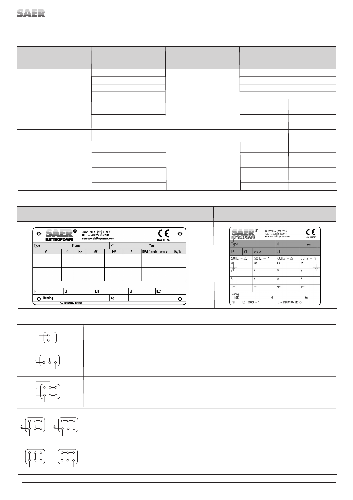
Dopo aver verificato i dati indicati sulla targa, procedere al collegamento elettrico sui morsetti del motore in osservanza degli schemi di Fig. 2 e
degli schemi presenti all'interno della scatola morsettiera, in funzione della tensione e del numero di fasi della linea di alimentazione.
Avviamento diretto (DOL): il motore può essere usato sia con collegamento a stella che a triangolo rispettando le relative tensioni di alimentazione.
La tensione ed il collegamento sono riportati sulla targa del motore.
Avviamento stella/triangolo (Y/D): la tensione di alimentazione è la tensione in collegamento a triangolo (D)
Motori monofase: il condensatore può mantenere i morsetti in tensione anche dopo che il motore è stato fermato.
Assicurarsi che la scatola della morsettiera sia sigillata e protetta da ingressi di polvere e acqua in modo da garantire il necessario
grado IP. Gli ingressi non utilizzati devono essere chiusi e sigillati.
APPLICAZIONE CON CONVERTITORI DI FREQUENZA (INVERTER)
I motori SAER possono essere utilizzati in versione standard con convertitori di frequenza nelle seguenti condizioni:
•Pn ≤75 kW
•Tensione nominale di alimentazione Un ≤500 V
Il convertitore di frequenza deve essere dotato degli opportuni filtri dU/dt in uscita. Si raccomanda inoltre l'uso di cavi simmetrici schermati e di
pressacavi EMC (obbligatori per potenze superiori a 30 kW). Deve essere assicurata l'equipotenzialità tra motore e dispositivo condotto.
Devono essere rispettate le prescrizioni del costruttore del convertitore di frequenza e le normative in vigore.
I parametri di impostazione del convertitore devono rispettare i dati di targa del motore.
Utilizzare e impostare correttamente tutte le protezioni presenti nel convertitore.
Assicurarsi che la velocità di rotazione non possa superare il valore massimo previsto, indicato in targa.
Per condizioni diverse (Pn > 75 kW o Un > 500 V) contattare l'assistenza tecnica SAER.
ATTENZIONE
ATTENZIONE

ELETTROPOMPE
®
I
8
7. MANUTENZIONE
Prima di effettuare qualsiasi operazione, togliere la corrente e assicurarsi che non possa essere ripristinata.
Attendere che la temperatura del motore sia tale da non creare pericolo di bruciature.
L'operatore deve adottare le opportune protezioni individuali (maschera, occhiali, guanti, ecc…)
Gli intervalli di manutenzione e di ispezione devono essere stabiliti in base al tipo di applicazione, alle condizioni ambientali (temperatura, umidità,
polvere…) e al verificarsi di eventi straordinari (sovraccarichi, sbalzi di tensione, eventi atmosferici ecc…). In ogni caso, devono essere rispettate
le seguenti prescrizioni minime:
•Ispezione visiva e verifica del corretto funzionamento: dopo le prime 500 ore e almeno ogni 6 mesi
•Pulizia e drenaggio delle condense: in base alle condizioni ambientali
•Ingrassaggio o sostituzione dei cuscinetti secondo TAB.VII - TAB.VIII
•Manutenzione completa ogni 20.000 ore di funzionamento
Lubrificazione dei cuscinetti
Il tipo dei cuscinetti è riportato sulla targa del motore
Motori con cuscinetti prelubrificati a grasso permanente: per i motori fino a grandezza costruttiva 180, i cuscinetti sono del tipo prelubrificato
a vita (mediante grasso) e pertanto non richiedono manutenzione. Gli intervalli di sostituzione indicativi sono riportati in TAB.VII (durata prevista
secondo L10)
Motori con cuscinetti ingrassabili: i motori con grandezza costruttiva superiore a 180 sono dotati di appositi ingrassatori. Se il motore riporta
la targhetta con i dati per l'ingrassaggio, seguire le indicazioni di targa. Diversamente attenersi alle seguenti indicazioni di massima:
•Quantità di grasso: deve essere iniettata una quantità di grasso tale da riempire il cuscinetto e circa il 40% dello spazio libero nel supporto.
•Intervallo di lubrificazione: vedere TAB.VIII
Non mischiare tipi diversi di grasso.
Non introdurre sostanze contaminanti nel cuscinetto, nel supporto o nel grasso.
Procedura per l'ingrassaggio
E' consigliabile eseguire l'ingrassaggio con il motore in funzione secondo la seguente procedura:
- aprire i tappi / valvole di carico e di scarico del grasso;
- pulire i fori di inserimento del grasso;
- verificare che il canale di lubrificazione sia libero;
- inserire la quantità di grasso richiesta tramite idoneo ingrassatore;
- far funzionare il motore per circa 30 min per far fuoriuscire il grasso in eccesso;
- richiudere i tappi / valvole.
Nel caso in cui si debba eseguire l'operazione a motore fermo:
- introdurre una quantità di grasso inferiore al necessario;
- far funzionare il motore per alcuni minuti a velocità nominale;
- fermare il motore ed eseguire il rabbocco del grasso necessario;
- far funzionare il motore per circa 30 min per far fuoriuscire il grasso in eccesso;
Caratteristiche dei grassi da utilizzare per condizioni normali di funzionamento (Tamb = -10°C + 40°C, Tmax cuscinetti = 110°C).
- Olio di base: minerale o PAO
- Addensante: sapone di litio
- Gamma di temperatura: -30°C - +120°C
- Classe NLGI: 2
- Viscosità dell'olio di base a 40°C: 110 mm2/s
Alcuni tipi di grasso utilizzabili:
- AGIP ROCOL Sapphire 2
- CHEVRON SRI2
- SKF LGMT2 o LGMT3
- EXXON UNIREX N3
- SHELL ALVANIA2
- KLUBER CENTOPLEXGL2N
- TOTAL MULTIS COMPLEX S2A
Per condizioni di impiego diverse contattare l'assistenza tecnica SAER o fare riferimento alla documentazione specifica dei cuscinetti.
Smaltire il grasso residuo e quello usato rispettando le normative vigenti.
ARRESTO
Se possibile, prima di eseguire l'arresto ridurre il carico del dispositivo condotto.
Utilizzare gli appositi interruttori per eseguire l'arresto.
Dopo aver fermato il motore, eventuali dispositivi anticondensa (opzionali) devono essere accesi.
CONSERVAZIONE
Motore installato, inattivo ma pronto ad essere avviato: mettere in funzione il motore per almeno 10 minuti una volta al mese.
Motore rimosso dall'impianto e immagazzinato: proteggere le superfici da pericoli di corrosione applicando prodotti idonei.
ATTENZIONE
ATTENZIONE

8. MESSA FUORI SERVIZIO E SMALTIMENTO
Al termine della vita operativa della pompa o di alcune sue parti, lo smaltimento deve essere fatto nel rispetto delle normative vigenti. Questo
vale anche per il liquido contenuto, con particolare riguardo se è classificato tossico o nocivo.
9. GUASTI, CAUSE E RIMEDI
10. PARTI DI RICAMBIO
Utilizzare solo parti di ricambio originali. Per le parti di ricambio fare riferimento ai cataloghi o contattare l'assistenza tecnica SAER, specificando
tipo di motore, n°di matricola e anno di costruzione rilevabili dalla targa identificativa.Il presente prodotto e' esente da vizi costruttivi.
INCONVENIENTI
ELETTROPOMPE
®
9
I
CAUSE RIMEDI
Il motore non parte e non si avverte alcun rumore o vibrazione
Non arriva tensione al cavo motore. Controllare l'apparecchiatura e/o linea elettrica.
I fusibili sono bruciati. Sostit. fusibili con altri dello stesso valore.
Cavo del motore interrotto. Riparare o sostituire il cavo.
Motore guasto. Sostituire il motore.
Il motore non parte e si avvertono rumori e/o vibrazioni
Il motore è collegato in modo errato. Correggere qualsiasi collegamento errato (vedi “collegamento elettrico”).
Il condensatore è guasto (solo monofase). Sostituire il condensatore.
La parte rotante è frenata. Smontare e rimuovere la causa.
Scattano i dispositivi di protezione elettrica
La tensione di alimentazione non è uguale a quella di targa del motore. Cambiare tensione o motore.
Un cavo è a massa o in corto circuito. Riparare o sostituire il cavo.
L'avvolgimento è a massa. Smontare il motore e rifare l'avvolgimento o sostituire il motore.
Morsetti dei cavi allentati. Serrare tutti i morsetti.
La parte rotante è bloccata. Smontare e rimuovere la causa.
La velocità dal motore è inferiore a quella nominale
Tensione troppo bassa ai terminali del motore Verificare la linea, le connessioni (lungo la linea e nel motore) e le sezioni dei cavi.
Contatti incerti nell'avviatore o nel cavo di alimentazione Controllare i contatti
Consumo di corrente eccessivo
Sovraccarico Ridurre il carico o sostituire il motore con uno più potente
Tensione inferiore a quella nominale Verificare la linea di alimentazione e le dimensioni dei cavi
Tensione superiore alla nominale Controllare la linea di alimentazione
Surriscaldamento eccessivo
Sovraccarico Ridurre il carico o sostituire il motore con uno più potente
Tensione diversa dalla nominale Verificare la linea di alimentazione e le dimensioni dei cavi
Temperatura ambiente elevata Condizionare l'ambiente o sostituire il motore
Ventilazione ostruita o inadeguata Verificare che la ventilazione non sia impedita o che i condotti non siano ostruiti
Tensioni sbilanciate Verificare la linea di alimentazione
Vibrazioni eccessive
Allineamento non corretto Verificare l'allineamento tra motore e macchina condotta
Pulegge non allineate Allineare le pulegge
Parti condotte non bilanciate Bilanciare le parti condotte (giunti, macchine ecc…)
Basamento inadeguato Rinforzare il basamento e il fissaggio
Bilanciamento del giunto diverso da quello dell'albero motore (vedi Par. 4) Bilanciare il giunto
Funzionamento in monofase (per motori trifase) Verificare i collegamenti ed eventuali corto circuiti nello statore.
Rumorosità eccessiva
Sistemi di fissaggio allentati Verificare il corretto serraggio di viti, bulloni ecc…
Sfregamento tra parti Verificare l'assenza di sfregamento delle parti in rotazione (ventola, rotore) e
l'assenza di corpi estranei all'interno del motore
Cuscinetti non lubrificati o danneggiati Verificare lo stato dei cuscinetti e la loro corretta lubrificazione
Rumore causato dalla macchina condotta Verificare la macchina condotta
Surriscaldamento dei cuscinetti
Allineamento non corretto Verificare l'allineamento tra motore e macchina condotta
Vibrazioni eccessive Ridurre l evibrazioni
Lubrificazione inadeguata Verificare la quantità (troppo o troppo poco) e il tipo di grasso
Cuscinetti danneggiati Sostituire i cuscinetti
Albero o sede cuscinetti danneggiati Sostituire i componenti danneggiati
Trazione della cinghia eccessiva Ridurre la trazione della cinghia

ELETTROPOMPE
®
GB
10
Cautionary warning to be followed to
guarantee the safety of the operator and
those persons present in the work area.
Failure to comply with
instructions may result in
electric shock.
Failure to comply with instructions may
result in damage to the motor or to the
system.
1. GENERAL INFORMATION
Before performing any operation on the machine, it is indispensable that you be completely familiar with the entire use and maintenance manual.
The manufacturer declines all responsibility for improper use of the product, for damage caused following operations not contemplated in this
manual or unreasonable interventions. Instructions and limitations contained in this manual are in reference to standard models. For all other
versions and all other situation non contemplated in the manual you should contact the technical service.
Each transport, installation, connection, setting at work, control and eventual maintenance or stop operation shall be executed by
trained and qualified staff. Furthermore, possible local regulations or directions not mentioned in this manual must be taken into
consideration as well. For trained and qualified staff make reference to the definition stated in the IEC 60364.
Tampering with the product is prohibited.
The user is responsible for dangers or accidents in relation to other persons and their property.
Use the motor only for the purposes described in Paragraph 4. Any other use can be a cause of accidents.
Before executing any operation, the feeder cables shall be disconnected.
Never touch the electric pump while it is working.
The motor is a device that must be integrated with other devices to become a machine for specific applications. It's use is not allowed
until the conformity to the Machines Directive of the final assembly (machine) is not certain.
2. SAFETY INFORMATION
3. TRANSPORT, HANDLING AND INTERMEDIATE STORAGE
The motor has to be lifted by means of a suitable lifting device. Specific eyebolts must be used: they are sized to stand only the weight of the
motors
Check the conditions for the eyebolts and their correct clamping before starting to lift the motor
Use suitable means for lifting and transporting the motor: it may be damaged if it is knocked or if it falls, even if there is no apparent
external damage, and it may also damage things or persons. Disconnect lifting tools and devices before starting the motor.
Storage conditions: store the motor in a covered and dry place, lacking dust, freeze and vibrations.
Minimum storage temperature= -20°C
Metallic exposed surfaces (shaft ends, flanges) must be protected in a suitable way to prevent corrosion.
4. TECHNICAL SPECIFICATIONS AND USE
Product description - Standard version
Low voltage three phases motor: totally enclosed fan cooled induction motors with squirrel cage rotor (TEFC). Shaft with cylindrical end and
key connection.
Method of cooling: IC 411 according to IEC 60034-6
The normalized motors have the dimensions according to IEC 60072-1
Insulation class: motors up to constructive size 71: B class, for bigger sizes: F class.
Protection degree: motors up to 71 constructive size : IP44, for bigger constructive sizes: IP55
Noise levels: refer to TAB.II
Up to 4 kW motors can be supplied also in one phase version with starting through electrolitic capacitor.
Shaft balancing: if not differently declared, shafts are balanced with half key.
USE
Motors for industrial use, conform to IEC 60034-1. The constructive sizes and possible installation positions are described in TAB.III
The identification data and technical characteristics of the motor are shown on the plate (fig. 1)
Never use the motor in explosive or hazardous gas atmospheres
Tension and frequency variations when working: respect A zone according to IEC 60034-1 (tension ±5%; frequency ±2%).
WARNING
WARNING
WARNING

ELETTROPOMPE
®
11
GB
5. INSTALLATION
Before executing any operation, turn off the power and prevent it from being reconnected.
- Preliminary verifications
√Verify that the data shown on the plate, and in particular, power, frequency, voltage, absorbed current, are compatible with the characteristics
of the electric line or current generator available.
√Verify that the protection and insulation grade indicated on the plate are compatible with the environmental conditions.
√Verificare che il motore non sia mai esposto alle intemperie.
√Verify the environmental conditions: SAER motor can be installed in enclosed or, at any rate, protected areas, with maximum ambient
temperature of + 40 °C in a non-explosive or non hazardous gas atmospheres.
√Check that the shaft of the motor turns manually, without noise or rubbings.
Insulation resistance control
√Check the insulation resistance: the insulation resistance of a new winding must be bigger than 10 MΩ with an ambient temperature of 20°C
with testing tension 500 V approx. Higher values of the ambient temperature reduce the insulation resistance values ( the value halves each
10°C of temperature increase). Disconnect the power cables before making the test. Make the test before the first starting and after long
periods of non operation.
Do not touch the motor during and after the measurement of the insulation resistance. After the measurement, discharge the winding
to avoid risks of electric shock.
Lubrication condition of bearings
Check the correct condition of lubrication of the bearings according to what stated in paragraph “Maintenace”
Foundations
√Make sure that the motor's support surface is solid and even (so that it rests on all the feet) and that the load capacity of the surface is
adequate for the weight shown on the plate. The levelness of the standing base of the foots must not be bigger than ±0,1mm.
√Verify that the surrounding area is sufficient for ventilation and allows movement in the case of maintenance.
√Check that the fixing point and the fixing surface prevent from the possible transmission of the vibrations to the surrounding structures.
√Check that the strength of the concrete foundations is appropriate and complies with current relevant regulations.
The motors provided with the feet should be fixed through the feet of the basement and with the appropriate supports.
The dimensions of the fixing bolts to the foundations and of connection of the flange to the driven machine, must be in accordance to EN 50347.
For recommended tightening torques see TAB. IV
Driven elements and alignment
The driven elements (couplings, pulleys, fans, etc.) must be coupled only through suitable devices and must have a suitable balancing
degree. In some case a complete machine balancing could be necessary (see ISO 10816)
√Check the cleanliness and regularity of all the supports and coupling surfaces.
Check the correct allignment of the coupling according to manufacturer's directions. A wrong allignment causes vibrations, damages
to the bearings and to the shaft.
Driving belts and pulleys: the tension of the driving belts must not be higher that the allowed values ( see the appropriate technical documentation).
Rotation direction
Before coupling the driven device, check the correct sense of rotation of the motor.
When checking the direction of rotation, secure the key to the shaft.
After the connection according to what specified in the specific paragraph, Quickly give and take off tension and observe the rotation direction
of the fan cooling motor through the carter which cover the fan.
In case of motor opposite rotation, reverse two phases on the terminal board.
ELECTRICAL CONNECTION
Before executing any operation, turn off the power and prevent it from being reconnected.
Check that in the housing box of the terminal block there are no dirt, powder, humidity or foreign bodies.
The minimum distance between the non insulated parts must be : ≥5,5 mm (Un ≤690 V), ≥8 mm (690 V < Un ≤1000 V)
Three phase motors, standard version: the connection terminal block has n.6 hubs. There can be further hubs for the connection of temperature
sensors (PTC, PT100…) and /or heating devices against condensation.
The motors are not provided with an electrical panel. The user is responsible for realizing and installing it.
WARNING
WARNING
WARNING
WARNING

ELETTROPOMPE
®
GB
12
6. SETTING AT WORK, OPERATION AND STOP
Before starting the motor effect the checks indicated in the previous paragraphs and also that:
√All the fixing, connecting, electrical connecting elements were shut with the appropriate pairs.
√The correct ventilation of the motor is guaranteed.
√The appropriate shelters of the moving parts are arranged.
The possibile anticondensation devices (optional) should be switched off before starting the motor
Feed current, waiting for the pump to reach full operating speed.
Assure that the rotating speed could not exceed the foreseen maximum value indicated on the plate.
CHECKS WHILE RUNNING
After a sufficient period of time to reach normal operation conditions, verify that:
√There are no vibrations or anomalous noises: the level of the vibrations should keep inside the values foreseen by ISO 10816.
√The ambient temperature does not exceed 40°C.
√The motors current absorption does not exceed that shown on the plate.
√The protection devices are not triggered.
In the presence of even only one of these conditions, stop the pump and find the cause.
Temperature of the bearings: the temperature of the bearings, measured on the external casing of the motor, may exceed the room temperature
of 55°C.
The external surface of the motor could reach the elevated values and cause burns if touched, also in normal working conditions. It
is recommended protecting it against accidental contacts, such as using grates or shieldings in such a way that however does not
affect correct ventilation.
Don't touch the motor and do not remove the shelters, covers and other devices while working.
Il The feeding cable should have adeguate section: make reference to IEC 60204-1
The connections should be effected in the way to remain sure during long time.
Install a magnetothermic differential switch of high sensivity (0, 03 A).
Connect the earthing cable in the proper position: it is possible to connect the earthing cable both inside the terminal box and outside
in the proper points. The cable should have the suitable cross-section according to the rules in force.
The connections in the terminal box should be tightened with the tightening torques indicated in the table V.
The connection to the power grid must be done in the respect of the local and national standards of the electric system of the place
where the pump is installed.
For the three-phase motors and the motors without any integrated protection device: use a thermal protection device adjusted on a maximum
absorbed current not higher than 5% the current stated in the label and with an operating time lower than 30 seconds.
After having checked the data indicated on the plate, proceed to connect the electricity to the motor terminals in observance of the diagrams in
fig. 2 and of the diagrams present inside of the terminal box, according to the voltage and number of phases of the power supply.
Direct start (DOL) the motor could be used both with the connection star and also delta respecting the relative voltages of the power supply. The
voltage and the connection are reported on the plate of the motor.
Star Delta start (Y/D): the voltage of the power supply is the voltage in the connection delta (D)
Single-phase motors: the capacitor could keep the terminals under voltage also after the motor is stopped.
Assure that the terminal box is sealed and protected from the entrance of dust and water in the way to guarantee the necessary IP
degree. The in-puts that are not in use should be closed and sealed.
APPLICATION WITH FREQUENCY CONVERTERS (INVERTERS)
The motors SAER could be used in standard version with the frequency converters in the following conditions:
•Pn ≤75 kW
•The nominal supply voltage Un ≤500 V
The frequency converter should be equipped with the appropriate filters dU/dt in out-put. It is also recommended the use of the symmetrical
screened cables and of the cable gland EMC (oblige for the powers more than 30 kW). The equipotentiality between the motor and the conducted
device is requested. It is necessary to respect the prescriptions of the constructor of the frequency converter and the rules in force. The parameters
of the converter's set up should respect the dates on the motor plate. Use and set up all the protections available in the converter in the right
way.
Assure that the rotation speed does not exceed the foreseen maximum value indicated on the plate.
For the other conditions (Pn > 75 kW or Un > 500 V) contact the technical assistance of SAER.
WARNING
WARNING

ELETTROPOMPE
®
13
GB
7. MAINTENANCE
Disconnect the motor from the electrical system and assure that it can not be connected before effecting any operation.
Await that the temperature of the motor is such not to create a danger of the burns.
The operator must wear suitable individual protection device (mask, goggles, gloves, etc.)
The maintenance and inspection intervals should be established on the basis of the application type, of the ambient conditions (temperature,
humidity, dust….) and of the appearance of the extraordinary events (overload, sudden changes of voltage, atmospheric events etc….). In any
case the following minimum prescriptions have to be followed:
•Visual inspection and check of the correct operation: after the first 500 hours and at least every 6 months.
•Cleaning and drainage of the condensation: on the basis of the ambient conditions.
•Greasing or changing of the bearings after the table VII.
•Complete maintenance every 20 000 hours of working.
Lubricating the bearings
The type of the bearings is indicated on the plate of the motor.
Motors with the bearings permanently lubricated with grease: for the motors up to the construction size 180 the bearings are of the permanently
lubricated type (with grease) and they do not request any maintenance. The intervals of the indicative changing are indicated in the table VII
(foreseen duration according to L10).
Motors with the greaseable bearings: the motors with the constructing size more than 180 are equipped with the appropriate lubricator. If the
motor is equipped with the indication for the lubrication on its plate, follow these indications.
Otherwise follow the present indications:
•Quantity of the grease: it should be injected such a quantity of the grease enough to fill the bearing and about 40% of the free space in the
support.
•Intervals of the lubrication: see table VIII
Do not mix different types of grease.
Do not introduce contaminating substances inside the bearing, the support and in the grease.
Procedure for the lubrication
It is recommended to effect the lubrication with the motor while working following the procedure:
- open the plugs/ valves of charging and discharging of the grease.
- clean the holes of the insertion of the grease.
- verify that the canal of the lubrication is free
- insert the requested quantity of the grease through the appropriate lubricator
- let the motor work for about 30 min in order to spill the superfluous quantity of the grease
- close the plugs/ valves
In the case if the operation is effected with the stopped motor:
- introduce a quantity of the grease that is inferior than necessary.
- let work the motor for several minutes at the nominal speed.
- stop the motor and effect the top up with the necessary quantity of the grease.
- Let work the motor for about 30 min in order to spill the superfluous quantity of the grease
Characteristics of the grease to be used for the normal working conditions (T amb. = -10°C – 40°C, Tmax bearings = 110°C).
- Basic oil: mineral or PAO
- Thickener: lithium soap
- Temperature range: -30°C - +120°C
- Class NLGI: 2
- Viscosity of the basic oil at 40°C: 110 mm2/s
Some types of the grease that are possible to be used
- AGIP ROCOL Sapphire 2
- CHEVRON SRI2
- SKF LGMT2 o LGMT3
- EXXON UNIREX N3
- SHELL ALVANIA2
- KLUBER CENTOPLEXGL2N
- TOTAL MULTIS COMPLEX S2A
For the other working conditions contact the technical assistance of SAER or refer to the specific documentation of the bearings.
Dispose of the residual grease and the used greased respecting the rules in force.
STOP
If possibile, reduce the charge of the conducted device before effecting the stop.
Use the proper switches for effecting of the stop.
Possible anti-condensation devices (optional) should be switched on after having stopped the motor
STORAGE
The motor installed, not in operation but ready to be started up: operate the motor for at least 10 minutes once a month. The motor removed
from the system and put into storage: protect the surface from corrosion by applying appropriate products.
WARNING
WARNING

ELETTROPOMPE
®
GB
14
8. DECOMISSIONING AND DISPOSAL
At the end of the operatine life of the motor or any of its parts, it must be disposed of in observance of current regulations. This is also valid for
the liquid contents, with particular regard if classified toxic or harmful.
9. TROUBLESHOOTING
10. SPARE PARTS
Use only original spare parts. To order spare parts, refer to the catalogues or contact the SAER Technical assistance specifying the kind of the motor,
the serial number and the year of manufacture (all these data are to be found in the identification plate). This product is free from the manufacturing defects.
PROBLEMS
CAUSES REMEDIES
The motor doesn't start and there is no noise or vibration
Novoltage in the motor cable Check the device and/or electric line
The fuses are burnt out Replace the fuses with others of the same value
Motor cable interrupted Repair or replace the cable
Motor broken Replace the motor
The motor does not start and there is noise and/or vibration
The motor was connected incorrectly Correct the incorrect connection (see “electrical connection”)
The capacitor is broken (for single-phase motor) Replace the capacitor
The rotatine parti s hindered. Disassemble and remove the cause
The electrical protection devices are triggered
The power supply voltage does not match that shown on the motor plate Ch'ange voltage or motor
The cable is grounded or has a short-circuit Repair or replace the cable
The winding is grounded Disassemble the motor and repeat the winding or replace the motor
Cable terminals loose Tighten all the terminal clamps
The rotatine parti s blocked Disassemble and remove the cause
The speed of the motor is less than the nominal one
The voltage is too low at the terminals of the motor Verify the line, the connections (along the line and in the motor) and the cross-section
of the cables.
Contacts are not sure inside the starter or in the feeding cable Check the contacts.
Exceeded consume of the current.
Overloading Reduce the charge or replace the motor with one of more power
Voltage less than the nominal one Verify the feeding line and the dimensions of the cables.
Voltage more than the nominal one Check the feeding line
Overheating
Overloading Reduce the charge or ch'ange the motor with one of more power.
Voltage different than the nominal one. Verify the feeling line and the dimensions of the cables.
Elevated ambient temperature Condition the ambient or replace the motor.
Obstructed or inadeguate ventilation Check that the ventilation or the pipes are not obstructed.
Unbalanced voltages Check the feeding line
Excessive vibrations
Wrong alignment Check the alignment between the motor and the conducted machine
Pulley not aligned Align the pulley
Unbalanced conducted parts Balance the conducted parts (joints, machine etc….)
Inadeguate basement Strengthen the basement and the fixing.
Counterbalance of the joint is different from the one of the motor shaft (see par. 4)
Balance the joint.
One-phase operation (for the three-phase motors) Check the connections and possibile short-circuit inside of the stator.
Excessive noise
Loosing fixing system Check the correct shutting of the screws, bolts etc….
Crackling between the parts Check the absence of the crackling of the rotating parts (fan, rotor) and the absence
of the extraneous bodies inside of the motor.
Bearings not lubricated or damaged Check the state of the bearings and their correct lubrication.
Noise conducted by the conducted machine Check the conducted machine.
Overheating of the bearings
Alignement is not correct Check the alignment between the motor and the conducted machine.
Excessive vibrations Reduce the vibrations
Inadeguate lubrication Check the quantity (too much or too little) and the type of the grease
Damaged bearings Replace the bearings
Shaft and place of the bearings are damaged Change the damaged components
Excessive traction of the belt Reduce the traction of the belt

ELETTROPOMPE
®
15
Legale rappresentante • Legal representative
Favella Franco
SAER Elettropompe S.p.A. , via Circonvallazione, 22 - 42016 Guastalla (RE) - Italy
Guastalla (RE) - Italy - 19/01/2010
I
GB
DICHIARAZIONE DI CONFORMITÀ
La Ditta SAER Elettropompe S.p.A. con sede in via Circonvallazione, 22 - 42016 Guastalla (RE) - Italy, dichiara che i motori elettrici serie
MT…
sono conformi alle prescrizioni della Direttiva Bassa Tensione (2006/95/CEE)
DECLARATION OF CONFORMITY
SAER Elettropompe S.p.A. with headquarters at Via Circonvallazione, 22 - 42016 Guastalla (RE) - Italy, hereby declares that the electric motors
series
MT…
are in conformity with the relevant provisions of the Low Voltage Directive (2006/95/EC)
DECLARACIÓN DE CONFORMIDAD

Cod.300-II / 80003015
• La ditta si riserva la facoltà di modificare senza preavviso i dati riportati in questo manuale.
• Saer can alter without notifications the data mentioned in this manual.
SAER ELETTROPOMPE S.p.A.
Via Circonvallazione, 22
42016 Guastalla (RE) Italy
Tel. 0522.83.09.41 r. a.
Fax 0522.82.69.48
e-mail: [email protected]
http://www.saerelettropompe.com
ELETTROPOMPE
®
• Questo manuale é da considerarsi parte integrante della fornitura del prodotto; qualora risultasse rovinato o illeggibile in qualsiasi parte
occorre richiederne immediatamente una copia. Ogni operatore addetto all’uso del prodotto, o responsabile della manutenzione, deve
conoscerne la collocazione e deve avere la possibilità di consultarlo in ogni momento.
• This manual is to be considered an integral part of the supply of the product; in the event it is ruined or any part is illegible, you should
immediately request a copy. Every operator assigned to use the product or responsible for its maintenance must know its location and must
be able to consult it at any time.
• Conservare il manuale per futuri riferimenti
• Keep the manual for future reference
•
Ulteriori informazioni su: www.saerelettropompe.com
•
For more information visit www.saerelettropompe.com
Organization with
Certified Quality System
ISO 9001:2008
Table of contents
Languages:
Other SAER Elettropompe Engine manuals
Popular Engine manuals by other brands

Westerbeke
Westerbeke W-13 Information sheet

Scania
Scania DC09 installation manual

Nice
Nice E EDGE SI 228 LI ION Instructions and warnings for installation and use

Carrier
Carrier 39E/ER Application data

Siemens
Siemens SIMOTICS L-1FN3 operating instructions

O.S. engine
O.S. engine OMA-2820-950 Owner's instruction manual