SAF-HOLLAND CBXA 40 User manual

XL-AS20053BM-en-US
Installation and Operation Manual
CBXA 40 Slider Suspension Systems
For Disc and Drum Brake Applications


XL-AS20053BM-en-US · 2016-09-27 · Amendments and Errors Reserved · © SAF-HOLLAND, Inc., SAF-HOLLAND, HOLLAND, SAF,
and logos are trademarks of SAF-HOLLAND S.A., SAF-HOLLAND GmbH, and SAF-HOLLAND, Inc.
Contents
3
Contents Page
Introduction......................................................................... 3
Warranty.............................................................................. 3
Notes, Cautions, and Warnings............................................. 3
Section 1 – General Safety Instructions ................................ 4
Section 2 – Standard Decal Requirements ............................ 5
Section 3 – PosiLok™Decal Requirements ............................ 7
Section 4 – CBXA 40 Model Identification ............................ 8
Section 5 – CBXA 40 Model Nomenclature........................... 8
Section 6 – Welding Standards............................................. 9
Section 7 – Standard Air Control System Installation .......... 10
Optional Air Release System Installation .......... 10
Optional PosiLok™System Installation.............. 10
Contents Page
Section 8 – Slider Assembly Installation ............................. 12
Section 9 – SwingAlign™Axle Alignment............................ 13
Section 10 – Brake Adjustment Instructions........................ 14
Section 11 – Pre-Operation Information ............................. 15
Section 12 – Slider Repositioning Instructions .................... 16
Section 13 – PosiLok™Anti-Dock Walk ............................... 18
Section 14 – Maintenance and Service Schedule................. 19
Section 15 – Torque Specifications ..................................... 20
Warranty
Refer to the complete warranty for the country in which
the product will be used. A copy of the written warranty is
included with the product or available on the internet at
www.safholland.com.
Notes, Cautions, and Warnings
Before starting any work on the unit, read and understand all
the safety procedures presented in this manual. This manual
contains the terms “NOTE”, “IMPORTANT”, “CAUTION”, and
“WARNING” followed by important product information. These
terms are defined as follows:
NOTE: Includes additional information to enable accurate
and easy performance of procedures.
IMPORTANT: Includes additional information that
if not followed could lead to hindered
product performance.
Used without the safety alert symbol,
indicates a potentially hazardous
situation which, if not avoided, could
result in property damage.
Indicates a potentially hazardous
situation which, if not avoided, could
result in minor or moderate injury.
Indicates a potentially hazardous
situation which, if not avoided, could
result in death or serious injury.
Introduction
This manual provides information necessary for the installation
and operation of the SAF-HOLLAND®CBXA 40 trailer air
suspension and slider system.
The CBXA 40 suspension includes premium 5.75" diameter
axles, For axle end and/or brake servicing information or
component replacements, refer to Drum Brake Manual XL-
TA10006OM-en-US, Disc Brake Manual XL-SA10059OM-en-US
or contact Customer Service at 888-396-6501.
This suspension uses air drawn from the tractor air system to
pressurize the air springs. The height control valve (HCV) regulates
the air pressure required for varying loads while maintaining the
design ride height. This suspension can provide a cushioned ride
throughout the load range, from empty to fully loaded.
The suspension also provides excellent side-to-side and
axle-to-axle loading which helps equalize and control braking.
Read this manual before using or servicing this product and
keep it in a safe location for future reference. Updates to this
manual, which are published as necessary, are available on
the internet at www.safholland.us.
When replacement parts are required, SAF-HOLLAND®
highly recommends the use of only SAF-HOLLAND®Original
Parts. A list of technical support locations that supply
SAF-HOLLAND® Original Parts and an Aftermarket Parts
Catalog are available on the internet at www.safholland.us
or contact Customer Service at 888-396-6501.

XL-AS20053BM-en-US · 2016-09-27 · Amendments and Errors Reserved · © SAF-HOLLAND, Inc., SAF-HOLLAND, HOLLAND, SAF,
and logos are trademarks of SAF-HOLLAND S.A., SAF-HOLLAND GmbH, and SAF-HOLLAND, Inc.
General Safety Instructions
4
Operational and Road Safety Instructions
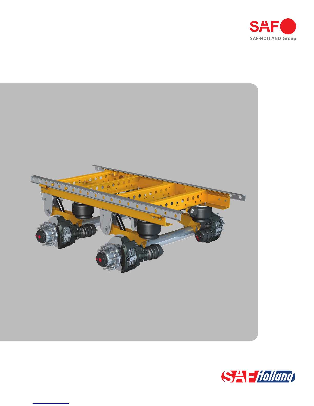
Before operating vehicle, ensure that the maximum permissible
axle load is NOT exceeded and that the load is distributed
equally and uniformly.
Make sure that the brakes are NOT overheated from
continuous operation.
Failure to minimize the use of brakes during
overheating conditions could result in
deterioration of brake efficiency which,
if not avoided, could result in death or
serious injury.
The parking brake MUST NOT be immediately applied when
the brakes are overheated.
If the parking brake is immediately applied
to the brakes when overheated, the brake
drums or discs could be damaged by different
stress fields during cooling.
Observe the operating recommendation of the trailer
manufacturer for off-road operation of the installed axles.
IMPORTANT: The definition of OFF-ROAD means driving
on non-asphalt/non-concrete routes, e.g.
gravel roads, agricultural and forestry tracks,
on construction sites and in gravel pits.
IMPORTANT: Off-road operation of axles beyond
the approved application design could
result in damage and impair suspension
system performance.
Follow the recommended routine maintenance and inspections
described in this manual. These procedures are designed so
that optimum performance and operational safety are achieved.
In the event of suspension air pressure loss, quickly reduce
speed as safely as possible and remove the vehicle from
traffic. If unable to remove vehicle from traffic, follow DOT
safety requirements regarding emergency situations.
Contact a qualified towing and/or service company to assist
in repairing the vehicle or to move it to a qualified repair facility.
DO NOT operate the vehicle in the absence of suspension
air pressure; however in the event of an air system failure
while in service, an internal rubber bumper built into the
air spring will make it possible to temporarily operate the
vehicle at reduced speed determined by road conditions.
Operating the vehicle without proper air
pressure can cause tire failure, fire, or loss
of vehicle control which, if not avoided,
could result in death or serious injury.
1. Safety Instructions
General and Servicing Safety Instructions
Read and observe all Warning and Caution hazard alert
messages. The alerts provide information that can help prevent
serious personal injury, damage to components, or both.
Failure to follow the instructions and safety
precautions in this manual could result in
improper servicing or operation leading
to component failure which, if not avoided,
could result in death or serious injury.
All maintenance should be performed by a properly
trained
technician using proper/special tools, and safe procedures.
NOTE: In the United States, workshop safety requirements
are defined by federal and/or state Occupational
Safety and Health Act (OSHA). Equivalent laws
could exist in other countries. This manual is written
based on the assumption that OSHA or other
applicable employee safety regulations are followed
by the location where work is performed.
Properly support and secure the vehicle from unexpected
movement when servicing the unit.
Failure to properly support and secure the
vehicle and axles prior to commencing work
could create a crush hazard which, if not
avoided, could result in death or serious injury.
If possible, unload the trailer before performing any
service procedures.
After re-positioning the brake chamber, slack adjuster and/
or ABS system as instructed in this manual, always consult
the manufacturer’s manual for proper operation.
Service both roadside and curbside of an axle. Worn parts
should be replaced in sets. Key components on each axle’s
braking system, such as friction material, rotors and drums
will normally wear over time.
Follow all manufacturer’s instructions on spring pressure
and/or air pressure controls.
Failure to follow manufacturer’s instructions
regarding spring pressure or air pressure
control could allow unexpected release of
energy which, if not avoided, could result
in death or serious injury.
DO NOT paint the wheel contact surfaces between the wheel
and hub.
IMPORTANT: The wheel contact surfaces MUST be clean,
smooth and free from grease.
Failure to keep wheel and hub contact surfaces
clean and clear of foreign material could
allow wheel/hub separations which, if not
avoided, could result in death or serious injury.
Only the wheel and tire sizes approved by the trailer builder
can be used.

5
XL-AS20053BM-en-US · 2016-09-27 · Amendments and Errors Reserved · © SAF-HOLLAND, Inc., SAF-HOLLAND, HOLLAND, SAF,
and logos are trademarks of SAF-HOLLAND S.A., SAF-HOLLAND GmbH, and SAF-HOLLAND, Inc.
Decal Requirements
2. Standard Decal Requirements
The following five (5) decals MUST be properly installed on
the trailer prior to putting it in service:
Tire Clearance Warning Decal: XL-AR356-01 (Figure 1).
Air Release Warning Decal: XL-AR429 (Figure 2).
Manual QWIK RELEASE®Warning Decal: XL-MS184 (Figure 3).
Figure 1
Figure 2
Figure 3
WARNING
Minimum tire clearance MUST be maintained between tires and
nearest point of contact on the suspension or vehicle. Premature
tire wear, fire or loss of vehicle control could result from contact
with the tires if clearances are not maintained.
XL-AR356-01
TIRE CLEARANCE REQUIREMENTS
• 1 INCH (25.4 mm) MINIMUM VERTICAL tire clearance is required between the top of the tire
and the nearest point of contact above the tire when the air pressure is completely exhausted
from the air suspension or when the axle is fully lifted if equipped with a suspension lift feature.
• 2 INCH (50.8 mm) MINIMUM LATERAL tire clearance is required between the sides of the
tire and the nearest point of contact through total travel of the air suspension. This includes
when the wheels are fully turned in either direction if equipped with an SAF Self Steer Axle.
www.safholland.us
Copyright © 2011 • SAF-HOLLAND, Inc.
WARNING
Failure to properly engage the lock pins could result in loss of vehicle control
which, if not avoided, could result in death, serious injury or property damage.
IMPORTANT: TRAILER EMERGENCY BRAKES MUST BE APPLIED BEFORE MANUAL
AIR RELEASE SWITCH WILL OPERATE.
TO REPOSITION SLIDER:
1. Remove stop bar and move to desired location.
2. Pull manual switch to “disengaged” position. (If lock pins do not
retract after manual switch is in “disengaged” position, gently rock
trailer and pins will automatically retract.)
3. Carefully move trailer until contacting stop bar.
4. Push manual switch to “engaged” position and visually check all lock
pins for proper engagement.
5. Locate stop bar directly behind slider.
6. Before using trailer, the manual air release lock switch must be in “engaged”
position, and all lock pins must extend through the rails or beams.
AIR RELEASE SWITCH
PUSH TO
“ENGAGE”
LOCK PINS
PULL TO
“DISENGAGE”
LOCK PINS
XL-AR429
www.safholland.usCopyright © 2012 • SAF-HOLLAND, Inc.
TO REPOSITION SLIDER:
1. Remove stop bar and move to desired location.
2. Lift pull arm and pull until locked in the “OUT” position. (If lock pins do not retract
after pull arm is locked in the “OUT” position, gently rock trailer with brakes
applied and pins will automatically retract.)
3. Apply trailer brakes and carefully move trailer until contacting stop bar.
4. Release pull arm to the “IN” position and visually check all lock
pins for proper engagement.
5. Locate stop bar directly behind slider.
6. Before moving the trailer, the pull arm must be locked in the “IN”
position, and all lock pins must extend through the rails or beams.
“IN”
POSITION
“OUT”
POSITION
XB-SL0255
XL-MS184www.safholland.us
Copyright © 2012 • SAF-HOLLAND, Inc.
WARNING
Failure to properly engage the lock pins could result in loss of vehicle
control which, if not avoided, could result in death, serious injury or
property damage.
It is the responsibility of the end user to periodically inspect
all decals and ensure that they are clean and completely legible.
If any decals are missing, loose, damaged or difficult to read,
contact SAF-HOLLAND®Customer Service at 888-396-6501 to
order replacements immediately.

6XL-AS20053BM-en-US · 2016-09-27 · Amendments and Errors Reserved · © SAF-HOLLAND, Inc., SAF-HOLLAND, HOLLAND, SAF,
and logos are trademarks of SAF-HOLLAND S.A., SAF-HOLLAND GmbH, and SAF-HOLLAND, Inc.
Decal Requirements
SwingAlign™Axle Alignment Decal: XL-AR372-01 (Figure 4).
Torque Decal: XL-AR418-01 (Figure 5).
It is the responsibility of the end user to periodically inspect
all decals and ensure that they are clean and completely legible.
If any decals are missing, loose, damaged or difficult to read,
contact SAF-HOLLAND®Customer Service at 888-396-6501
to order replacements immediately.
Figure 4
Figure 5
ALIGNMENT BOLT IS ON THE FRONT OF THE ROADSIDE FRAME BRACKET:
XL-AR372-01
STEP 1. Before aligning axle, pull trailer forward in a straight line for a sufficient distance to insure there are no binds
in the suspension and then lock the brakes so the slider lock pins rest against the rear of the body rail holes.
STEP 2. Check to verify trailer is empty and emergency brakes are NOT engaged.
STEP 3. Rotate bolt CLOCKWISE to move axle forward (A arrows); COUNTERCLOCKWISE to move axle rearward (B arrows).
A = axle forward
B = axle rearward
ALIGNMENT BOLT HEAD
NOTE: 1/2 turn of
free play in either
direction (A or B)
is acceptable.
SWINGALIGN™NON-WELDED AXLE ALIGNMENT PROCEDURES
www.safholland.us
Copyright © 2011 • SAF-HOLLAND, Inc.

7
XL-AS20053BM-en-US · 2016-09-27 · Amendments and Errors Reserved · © SAF-HOLLAND, Inc., SAF-HOLLAND, HOLLAND, SAF,
and logos are trademarks of SAF-HOLLAND S.A., SAF-HOLLAND GmbH, and SAF-HOLLAND, Inc.
Decal Requirements
3. PosiLok™(Optional Equipment)
Decal Requirements
The following decals MUST be installed on the trailer and
MUST be in plain sight of the operator:
PosiLok™Misuse Caution Decal: XL-AR437 (Figure 6).
Air Up Caution Decal: XL-AR439 (Figure 7).
Figure 6
Figure 7
It is the responsibility of the end user to periodically inspect
all decals and ensure that they are clean and completely legible.
If any labels are missing, loose, damaged or difficult to read,
contact SAF-HOLLAND®Customer Service at 888-396-6501
to order replacements immediately.
CAUTION
Failure to check for proper PosiLok™ position
could result in vehicle / suspension damage.
XL-AR437
WHEN TRAILER PARKED:
Check that the
PosiLok™ is in
the DOWN position.
PosiLok™
DOWN
BEFORE MOVING TRAILER:
Check that the
PosiLok™ is in
the UP position.
PosiLok™
UP
www.safholland.us
Copyright © 2011 • SAF-HOLLAND, Inc.
CAUTION
Suspension system must fully air up before moving trailer. Failure to wait before moving trailer
could result in suspension and/or slider damage.
XL-AR439www.safholland.us
Copyright © 2011 • SAF-HOLLAND, Inc.

8XL-AS20053BM-en-US · 2016-09-27 · Amendments and Errors Reserved · © SAF-HOLLAND, Inc., SAF-HOLLAND, HOLLAND, SAF,
and logos are trademarks of SAF-HOLLAND S.A., SAF-HOLLAND GmbH, and SAF-HOLLAND, Inc.
Model Identification and Nomenclature
4. CBXA 40 Model Identification
The CBXA 40 suspension serial tag is located on the rear
crossmember (Figure 8).
NOTE: Refer to the serial number tag attached to the slider
rear crossmember for information (Figure 8).
NOTE: If the suspension serial tag is not legible or is not
available, you can identify your suspension model
by the appearance of the equalizing beam. The
CBXA 40 model will have an H-shaped cast beam,
5.75" axle, and a lower air spring mounting plate
welded to the beam (Figure 8).
NOTE: This manual applies to the suspension models
listed on the front cover. However, we urge you to
determine your specific model number, write that
information below and refer to it when obtaining
information or replacement parts (Figure 9).
5. CBXA 40 Model Nomenclature
The sample tag illustrated will help you interpret the information
on the SAF-HOLLAND®, Inc. serial number tag. The model number
is on the first line along with the suspension capacity. The second
line contains the part number and the serial number (Figure 9).
Figure 9
Figure 8
TAG LOCATED ON
REAR CROSSMEMBER
CB X A 40 - 48 16
Cast Beam
Axle Capacity
Suspension Series
40,000 Tandem
Aero Beam
5.75" Diameter Premium Axle
Slider Box Width
42" (1067 mm) Wide
48" (1219 mm) Wide
54" (1372 mm) Wide
Ride Height
16" (406 mm)
16.5" (419 mm)
17" (432 mm)
18" (445 mm)
H-SHAPED CROSS
SECTION

XL-AS20053BM-en-US · 2016-09-27 · Amendments and Errors Reserved · © SAF-HOLLAND, Inc., SAF-HOLLAND, HOLLAND, SAF,
and logos are trademarks of SAF-HOLLAND S.A., SAF-HOLLAND GmbH, and SAF-HOLLAND, Inc.
Welding Standards
9
6. Welding Standards
6.1 Scope
The SAF®suspension has been designed to be installed on a
trailer with no welding required. When welding is required for
suspension repairs, observe the requirements below. Customers
may not weld on an SAF®suspension without our prior approval,
including the application of the American Welding Society standards
by SAF-HOLLAND®engineering. This specification applies to
all components supplied by SAF-HOLLAND®, and its products.
The customer assumes all responsibility for weld integrity if
weld material and procedure differ from those listed below.
6.2 Workmanship
All welding on SAF-HOLLAND®products MUST be performed
by a welder qualified according to the appropriate AWS
standard for the weld being made or an equivalent standard.
It is the responsibility of the customer to provide good
workmanship when welding on SAF-HOLLAND®products.
6.3 Material
Items to be welded that are made from low carbon or high-strength
alloy steel are to be welded with AWS filler metal specification
AWS A5.18, filler metal classification ER-70S-3, ER-70S-6 or
equivalent unless specified on the installation drawing.
NOTE: Any substitution for filler material from the above
standard must comply, as a minimum, with the
following mechanical properties:
Tensile Strength - 72k psi (496 MPa)
Yield Strength - 60k psi (414 MPa)
Charpy V Notch - 20 ft.-lbs. (27 N•m) at 0o F (-17.7o C)
% Elongation - 22%
The recommended welding gas for gas metal arc welding
(GMAW) is 90% Argon / 10% CO2. If a different gas is used,
welds must comply with penetration requirements illustrated
(Figure 10). Where the installation drawing specifies
different than above, the drawing shall prevail.
6.4 Procedures
Tack welds used for positioning components are to be located
in the center of the final weld, where practical. Tack weld
should be completely fused to the finish weld. DO NOT
break arc at the end of the weld. Back up all finish welds
at least 1/2" (12.7 mm) or a sufficient amount to prevent
craters at the end of the weld. Where weld is illustrated to go
around corners, it is assumed the corner represents a stress
concentration area. DO NOT start or stop weld within 1" (25.4 mm)
of the corner. Particular care should be taken to prevent
undercutting in this area.
6.5 Weld Size
If weld size is NOT specified, the effective throat of the weld
MUST be no smaller than the thinnest material being welded
(Figure 10).
Figure 10
LACK OF FUSION OF
ANY KIND IN THIS AREA
IS NOT ACCEPTABLE AT
ANY TIME
PENETRATION AS MEASURED
THROUGH SEAM
TARGET PENETRATION TO BE
10% OF THINNEST MATERIAL
FROM INTERSECTION OF FILLET
AS ILLUSTRATED
TARGET PENETRATION

XL-AS20053BM-en-US · 2016-09-27 · Amendments and Errors Reserved · © SAF-HOLLAND, Inc., SAF-HOLLAND, HOLLAND, SAF,
and logos are trademarks of SAF-HOLLAND S.A., SAF-HOLLAND GmbH, and SAF-HOLLAND, Inc.
Installation Instructions
10
7. Standard Air Control
System Installation
1. Install air reservoir, mud flap and stinger brackets. Grind
off paint and prepare all surfaces for welding. Refer to
welding standards detailed in Section 6 of this manual.
2. Install the air reservoir to the air reservoir brackets.
3. Plumb the air control system as illustrated (Figure 11).
The air control system of the CBXA 40 suspension uses
air drawn from the tractor air system to pressurize the
suspension’s air springs. The suspension, working with the air
control system, provides optimum suspension performance
only when all air control system components are installed and
operating properly.
IMPORTANT: Make certain that all air lines and valves
are free from obstruction through the full
operational range of the suspension.
IMPORTANT: A pressure protection valve (PPV) must
be attached to the air reservoir in order
to maintain proper air pressure in the air
reservoir (Figure 11).
IMPORTANT: The pressure protection valve maintains safe
brake pressure. Approximately 85 psig (5.9
bars) opens the valve, and 65 psig
(4.5 bars) closes the valve.
NOTE: When installing pressure protection valve, use
a drop of oil or loctite to lubricate threaded
connections. DO NOT use a pipe compound or
teflon tape as they could clog the valve.
A height control valve (HCV) is used to regulate the air spring
pressure required for varying load capacities (Figure 11).
Optional Air Release System
If your CBXA 40 was ordered with a slider pull pin air release
system, the air release control valve and the actuator will
need to be plumbed (Figure 11.A).
Optional PosiLok™System
If your CBXA 40 was ordered with a PosiLok™anti-dock
walk system, the PosiLok™actuator will need to be plumbed
(Figure 11.B).

XL-AS20053BM-en-US · 2016-09-27 · Amendments and Errors Reserved · © SAF-HOLLAND, Inc., SAF-HOLLAND, HOLLAND, SAF,
and logos are trademarks of SAF-HOLLAND S.A., SAF-HOLLAND GmbH, and SAF-HOLLAND, Inc.
Installation Instructions
11
Figure 11
Figure 11.A OPTIONAL AIR RELEASE SYSTEM Figure 11.B OPTIONAL POSILOK™SYSTEM
HEIGHT CONTROL
VALVE (HCV)
POSILOK™
ACTUATOR
TO PPV AND
AIR RESERVOIR
TO GLAD HAND OR
EMERGENCY BRAKE
STANDARD AIR CONTROL SYSTEM
AIR RESERVOIR
PRESSURE PROTECTION
VALVE (PPV)
HEIGHT CONTROL
VALVE (HCV)
TO HEIGHT CONTROL
VALVE (HCV)
TO GLAD HAND OR
EMERGENCY BRAKE
AIR SPRING
AIR SPRING
AIR SPRING
AIR SPRING
TO AIR SUPPLY
TO AIR SPRINGS
TO AIR SPRINGS
CONTROL ARM
(NEUTRAL POSITION)
AIR RELEASE
CONTROL VALVE SLIDER PULL PIN
RELEASE ACTUATOR
PRESSURE
PROTECTION
VALVE (PPV)
TO GLAD HAND
OR EMERGENCY
BRAKE
CYL
RESET
N.C.
POSILOK™
ACTUATOR

XL-AS20053BM-en-US · 2016-09-27 · Amendments and Errors Reserved · © SAF-HOLLAND, Inc., SAF-HOLLAND, HOLLAND, SAF,
and logos are trademarks of SAF-HOLLAND S.A., SAF-HOLLAND GmbH, and SAF-HOLLAND, Inc.
Installation Instructions
12
Figure 13
Figure 14
Figure 12
8. Slider Assembly Installation
1. Remove the hold down clips on all four (4) corners of
the slider.
2. Locate the slider between the body rails of the trailer and
engage the lock pins. Refer to the slider re-positioning
operating instructions in Section 12 of this manual.
3. Once the slider is correctly positioned, re-install the hold
down clips to the slider and body rails, and torque all
1/2" hold down clip nuts to 75-90 ft.-lbs. (102-122 N•m).
4. Ensure the linkage assembled to the height control valve (HCV)
and suspension is of the appropriate height (Figure 12).
IMPORTANT: A 15" linkage is used for ride heights of
16"-17". A 16" linkage is required for 18"
ride heights (Figure 12).
Failure to match the linkage length to the
design ride height could result in improper
suspension height which, if not avoided,
could result in damage to trailer components.
5. Install service and emergency lines to the slider and
allow the suspension to air up.
6. Measure the ride height of the suspension (Figure 13)
with a tape measure.
7. Compare the measured suspension ride height value to
the appropriate value (Table 1). Ensure your measured
ride height value is within ±1/4" (6 mm).
IMPORTANT: If your measured ride height value is NOT
within ±1/4"(6 mm); use the table to verify
the linkage length (Table 2 and Figure 12),
and the hole location where the top mounting
stud of the height control valve (HCV) is
bolted to the mounting bracket (Figure 14).
8. Visually check all air control system fittings for air leaks
by applying a soapy water solution and checking for
bubbles at all air connections and fittings.
LOWER LINKAGE
CONNECTION
HEIGHT CONTROL
VALVE ARM
RIDE HEIGHT HOLE LOCATION LINKAGE LENGTH
16" 2ND HOLE 15"
16.5" 3RD HOLE 15"
17" 4TH HOLE 15"
18" 4TH HOLE 16"
Table 2
HEIGHT CONTROL VALVE
MOUNTING BRACKET
TOP HOLE
2ND HOLE
3RD HOLE
4TH HOLE
CBXA 40 “A” RIDE HEIGHT
4216 / 4816 / 5416* 16"
4216.5 / 4816.5 / 5416.5* 16.5"
4217 / 4817 / 5417* 17"
4218 / 4818 / 5418* 18"
*These numbers refer to the last digits of the model number.
Table 1
“A”
RIDE
HEIGHT
15" LINKAGE
LENGTH STANDARD
(18" RIDE HEIGHT
REQUIRES 16" LINKAGE)

XL-AS20053BM-en-US · 2016-09-27 · Amendments and Errors Reserved · © SAF-HOLLAND, Inc., SAF-HOLLAND, HOLLAND, SAF,
and logos are trademarks of SAF-HOLLAND S.A., SAF-HOLLAND GmbH, and SAF-HOLLAND, Inc.
Installation Instructions
13
Figure 16
Figure 17
A
KINGPIN
B
D
C
Figure 15
ALIGNMENT
BOLT
WASHER
“A” ARROWS - AXLE FORWARD
“B” ARROWS - AXLE REARWARD
NOTE: 1/2 TURN OF FREE PLAY
IS ACCEPTABLE
9. SwingAlign™Axle Alignment
IMPORTANT: Axle alignment can only be achieved if the
lockpin holes are the same distance from the
kingpin, left and right. Axle alignment should
ALWAYS be done while the trailer is empty.
9.1 Alignment Preparation
1. Pull the trailer in a straight line for a sufficient distance
to ensure there are no binds in the suspension.
2. Lock the trailer brakes and pull the trailer straight forward
so the locking pins rest against the rear of the holes in
the body rails.
3. Disengage the trailer parking brakes and ensure the
trailer is empty.
4. Manually measure or use an optical device specifically
designed for alignment measuring to determine the following:
a. For proper alignment, measure the distance from the
king pin to the centerline of the front axle spindles. It
is recommended that spindle extensions be utilized.
Dimensions A and B (Figure 15) MUST be equal to
within 1/8" (3 mm).
b. For proper alignment, measure the distance from the
centerline of the front axle spindles to the centerline of
the rear axle spindles.
Dimensions C and D (Figure 15) MUST be equal to
within 1/16" (1 mm).
9.2 Alignment Instructions
1. Using the measurements from Step 4, align each axle.
Align by rotating the alignment bolt head using a 1-3/8"
socket wrench on the front face of the roadside frame
bracket. Rotate clockwise to move axle forward
(A Arrows); counterclockwise to move axle rearward
(B Arrows) (Figure 16). Approximately 250 ft.-lbs.
(339 N•m) will be required.
IMPORTANT: DO NOT loosen the pivot bolt.
IMPORTANT: Two (2) scribe lines on the side of the frame
bracket indicate maximum adjustment for axle
alignment. If the edge of the visible washer
touches either scribe line the SwingAlign™
axle alignment adjustment is “out of stroke”
(Figure 17). Inspect and repair trailer
components as necessary and realign.
IMPORTANT: The SwingAlign™design maintains proper
alignment without welding and without
loosening of the pivot connection. DO NOT
weld alignment bolt or pivot bolts.
(Figure 17). If connection requires tightening,
use a 1-11/16" socket wrench and torque to
550-600 ft.-lbs. (746-813 N•m)
ALIGNMENT BOLT ASSEMBLY
WASHER ALIGNMENT PLATES
SCRIBE
LINES
PIVOT BOLT
ALIGNMENT BOLT
A = B ±1/8" (3 mm)
C = D ±1/16" (1.6 mm)

XL-AS20053BM-en-US · 2016-09-27 · Amendments and Errors Reserved · © SAF-HOLLAND, Inc., SAF-HOLLAND, HOLLAND, SAF,
and logos are trademarks of SAF-HOLLAND S.A., SAF-HOLLAND GmbH, and SAF-HOLLAND, Inc.
Installation Instructions
14
NOTE: Alignment plates are NOT welded to the frame
bracket, but are free to rotate.
2. Relocate the slider to the forward position and recheck the
king pin alignment. Variance in dimensions “A” and “B”
(Figure 18) indicates there are discrepancies in lock pin
hole location.
10. Brake Adjustment Instructions
Brakes should be adjusted per axle and brake manufacturer’s
specifications.
A
KINGPIN
B
D
C
Figure 18
A = B ±1/8" (3 mm)
C = D ±1/16" (1.6 mm)

XL-AS20053BM-en-US · 2016-09-27 · Amendments and Errors Reserved · © SAF-HOLLAND, Inc., SAF-HOLLAND, HOLLAND, SAF,
and logos are trademarks of SAF-HOLLAND S.A., SAF-HOLLAND GmbH, and SAF-HOLLAND, Inc.
Pre-Operation Information
15
11. Pre-Operation
1. With the vehicle on a level surface, bring air system to
operating pressure, above 85 psig/5.9 bars.
2. Shut off the vehicle and inspect all air control system
fittings for air leaks by applying a soapy water solution
and checking for bubbles at all connections and fittings.
Examine the air springs (Figure 19) for equal firmness.
IMPORTANT: It is the responsibility of the air system
installer to secure all air lines and check
for any air leaks. If air leaks are detected,
repair is required.
Failure to eliminate air leaks could
compromise suspension’s performance
which, if not avoided, could result in
component or property damage.
3. Check the shock absorbers for proper installation and make
sure that the upper and lower 3/4" shock absorber nuts are
torqued to 140-175 ft.-lbs. (190-237 N•m) (Figure 19).
4. Verify that the 1/2" air spring mounting nuts are torqued to
30-40 ft.-lbs. (41-54 N•m), and the 3/4" air spring mounting
nuts are torqued to 40-45 ft.-lbs. (54-61 N•m) (Figure 19).
5. With the suspension at full capacity, check that there is a
1" (25 mm) minimum clearance around the air springs.
6. The suspension’s ride height should be within ±1/4" (6 mm)
of the recommended design height. For proper height,
refer to Ride Height Adjustment Section 7.
7. Verify that the 1-1/8" pivot nut are torqued to 550-600 ft.-lbs.
(746-813 N•m) (Figure 23).
IMPORTANT: The SwingAlign™design maintains proper
alignment under correct torque without
welding; DO NOT weld (Figure 19).
NOTE: SwingAlign™pivot connections are on roadside
and fixed alignment pivot connections are on
curbside. For SwingAlign™Connection Axle
Alignment procedure, refer to Section 9.
8. If the vehicle is equipped with a PosiLok™feature, make
sure there is a 1" (25 mm) minimum clearance between
the bottom of the flipper plate and the top of the beam
pad when at ride height (Figure 19); Refer to PosiLok™
Installation and Operation Manual XL-AR408 for more
information. Available at www.safholland.us or contact
SAF-HOLLAND®Customer Service at 888-396-6501.
9. Check that the slider locking pins, slider pull-bar mechanism,
and slider wear pads (Figure 19) are operating properly.
For slider repositioning instructions, Refer to procedures
described in Section 12 of this manual.
10. Inspect the front and rear hold down clips (Figure 19)
to make sure that they are correctly secured around the
slider body rails. Torque all 1/2" hold down clip nuts
to 75-90 ft.-lbs. (102-122 N•m).
Figure 19
AIR SPRING
MOUNTING NUT
REAR HOLD
DOWN CLIP
MANUAL
STOP BAR
FRONT HOLD
DOWN CLIP
OPTIONAL
AIR RELEASE
SHOCK ABSORBER
SLIDER
BODY RAILS
SLIDER LOCK PINS
SLIDER LOCK PINS
AIR SPRING
OPTIONAL
POSILOK™
FLIPPER PLATE
SWINGALIGN™
ADJUSTMENT NUT
1- 1/8"
PIVOT NUT

XL-AS20053BM-en-US · 2016-09-27 · Amendments and Errors Reserved · © SAF-HOLLAND, Inc., SAF-HOLLAND, HOLLAND, SAF,
and logos are trademarks of SAF-HOLLAND S.A., SAF-HOLLAND GmbH, and SAF-HOLLAND, Inc.
PULL ARM
HANDLE
LOCK PINS
ENGAGED
ENGAGED POSITION
NOTCH 1
NOTCH 2
Operation Instructions
16
Figure 21
Figure 22
Figure 20
12. Slider Repositioning Instructions
1. With the vehicle on a level surface, set the tractor and
trailer brakes and locate the slider QWIK RELEASE®pull
arm handle (Figure 20), or air release control valve.
2. To reposition the slider, remove the manual stop bar
and relocate to desired location – rearward of slide box
if moving rearward, or forward of slide box if moving
forward (Figure 20).
If repositioning the slider forward, remove the manual
stop bar and relocate directly behind slide box after the
slider is moved to final position.
3. Lift and pull the QWIK RELEASE®pull arm handle from
the engaged position (Notch 1 - Figure 21) to the
disengaged position (Notch 2 - Figure 22).
NOTE: If your slider is equipped with an air release pin
mechanism, pull the air release control valve knob
to disengage the lock pins.
4. Visually check to ensure the lock pins are in the disengaged
position, and that the QWIK RELEASE®pull arm handle is
locked (Notch 2 - Figure 22).
When lock pins have properly disengaged, proceed to
Step 6.
If lock pins fail to disengage, proceed to Step 5.
5. If the QWIK RELEASE®pull handle is in the notch 2
position but the lock pins fail to retract and are still
in the engaged position, the QWIK RELEASE®pull
arm is in an armed, ready to unlock position.
NOTE: The QWIK RELEASE®torsion spring will
automatically retract the lock pins when
the pressure on the lock pins is released.
a. Release the tractor brakes.
Failure to verify the area is clear of
others before moving the vehicle could
result in death or serious injury.
b. Gently rock the tractor and trailer fore and aft while
listening for the lock pins to disengage.
c. After the “metallic clang” of the lock pins disengaging
is heard, reset the tractor brakes, and visually verify
that the lock pins have been properly disengaged.
If pins DO NOT disengage:
d. Put air pressure back to the trailer emergency brakes.
RELOCATED
MANUAL
STOP BAR
MANUAL
STOP BAR
PULL ARM
HANDLE
PULL ARM
HANDLE
DISENGAGED POSITION
NOTCH 1
NOTCH 2
LOCK PINS
DIS-ENGAGED

XL-AS20053BM-en-US · 2016-09-27 · Amendments and Errors Reserved · © SAF-HOLLAND, Inc., SAF-HOLLAND, HOLLAND, SAF,
and logos are trademarks of SAF-HOLLAND S.A., SAF-HOLLAND GmbH, and SAF-HOLLAND, Inc.
PULL ARM
HANDLE
ENGAGED POSITION
NOTCH 1
NOTCH 2
PULL ARM
HANDLE
DISENGAGED POSITION
NOTCH 1
NOTCH 2
e. Pull the trailer as straight as possible for ten (10) to
fifteen (15) feet.
f. Repeat steps 5.a., 5.b. and 5.c. until pins dis engage.
NOTE: If unable to move slider after multiple attempts, a
maintenance inspection may be necessary.
Hazardous conditions may be present
if the slider DOES NOT move after
multiple attempts. Failure to conduct a
maintenance inspection may result in
death or serious injury.
6. When the lock pins have disengaged – slowly reposition
the tractor until the slide box contacts the manual stop
bar (Figure 20).
7. a. Set the tractor brakes.
NOTE: Trailer parking brakes should still be engaged.
b. Lift and push the pull arm handle from the disengaged
position (Notch 2 - Figure 23) to the engaged
position (Notch 1 - Figure 24).
NOTE: If your slider is equipped with an air release pin
mechanism, push the air release control valve
knob to engage the lock pins.
8. Visually check that the lock pins are fully engaged and
extend through the holes in the upper rail (Figure 25).
An unsecured slider box can cause loss
of vehicle control which, if not avoided,
could result in death, serious injury or
property damage.
9. Visually check that the manual stop bar is properly installed
directly behind slide box (Figure 25).
Failure to properly install or position the
manual stop bar could result in improper
trailer load distribution which, if not
avoided, could result in damage to the
suspension or trailer parts.
Operation Instructions
17
MANUAL
STOP BAR
LOCK PINS
ENGAGED
IN SLIDER RAIL
Figure 24
Figure 25
Figure 23

XL-AS20053BM-en-US · 2016-09-27 · Amendments and Errors Reserved · © SAF-HOLLAND, Inc., SAF-HOLLAND, HOLLAND, SAF,
and logos are trademarks of SAF-HOLLAND S.A., SAF-HOLLAND GmbH, and SAF-HOLLAND, Inc.
Operation Instructions
18
FLIPPER PLATE IN THE
ENGAGED POSITION
13. PosiLok™Anti-Dock Walk (Optional
Equipment)
The CBXA 40 suspension can be equipped with SAF®PosiLok™
which provides enhanced trailer stability during loading and
unloading operations. If the trailer air control system employs
a “spring brake priority” type arrangement, potential field
service issues could arise due to operational misuse, such as:
Moving a trailer before the air springs have been
properly inflated.
Use of yard hustler equipment.
Heavy load operations, such as paperhaul, with the slider
in the full forward position.
Engaging the emergency trailer brakes at a high rate of
speed (greater than 5 mph) to move the slider position.
Use of an auxiliary suspension dump valve with excessive flow.
Going in and out of ramped docks with slider all the
way forward.
SAF®PosiLok™system will properly support the trailer during
normal operations and is designed to bend or buckle when
subjected to overloading or other operational issues to
protect the trailer sub-frame.
The PosiLok™is engaged when the flipper
plates are in the down position.
1. Release air pressure from the trailer brake system or
disconnect the glad hand. This engages the parking
brakes and causes the PosiLok™actuator to engage,
which rotates the rod so the flipper plates swing down
into an engaged position (Figure 26).
The PosiLok™is disengaged when the flipper
plates are in the up position.
1. When the parking brakes are disengaged, the primary height
control valve (HCV) takes full function. When the system
has sufficient air pressure in the suspension air springs,
the actuator extends, rotating the rod so the flipper plates
swing up away from the load pads into a disengaged
position (Figure 27). The vehicle is now ready for movement.
IMPORTANT: DO NOT operate vehicle (put in motion) if
flipper plates are trapped in the down position
(Figure 28). Refer to the troubleshooting
section of Installation and Operation Manual
XL-AR408. Available at www.safholland.us
or contact SAF-HOLLAND®Customer Service
at 888-396-6501.
Failure to adequately raise flipper
plates could result in trailer, suspension
component, and cargo damage.
Figure 27
Figure 28
Figure 26
FLIPPER PLATE
TRAPPED IN THE
DOWN POSITION
FLIPPER PLATE IN THE
DISENGAGED POSITION

XL-AS20053BM-en-US · 2016-09-27 · Amendments and Errors Reserved · © SAF-HOLLAND, Inc., SAF-HOLLAND, HOLLAND, SAF,
and logos are trademarks of SAF-HOLLAND S.A., SAF-HOLLAND GmbH, and SAF-HOLLAND, Inc.
Maintenance and Service Schedule
19
14. Routine Maintenance and
Daily Inspection
1. Daily or before each trip, check the suspension to be sure
it is fully operational.
2. Inspect all decals to ensure they are clearly legible and
intact. Clean with a terry cloth towel, soap and water.
3. Visually inspect air springs for sufficient inflation and
that the suspension is at proper ride height. For ride
height details and measurements, refer to Section 8
of this manual.
4. Inspect the slider lock pins and slider pull handle for
signs of excessive wear, bending or binding.
5. Inspect the front and rear hold down clips to ensure that
they are correctly secured around the body rails.
14.1 Initial Three (3) Months or 5,000 Mile
(8,000 km) Service Inspection
1. Suspension ride height (underside of frame to centerline
of axle) MUST be within ±1/4" (6 mm) of recommended
design height. For instructions on measuring ride height,
refer to Section 8.
An improperly set ride height could result
in suspension component damage and/or
poor vehicle ride performance.
2. After first three (3) months or 5,000 miles (8,000 km)
of service, whichever comes first, inspect bolts and nuts
at the pivot connections to ensure they are properly
torqued. Check all other nuts and bolts for proper torque,
refer to the specifications listed in Section 15. Re-torque
as necessary thereafter.
3. With the vehicle on a level surface and air pressure above
85 psig (5.9 bars), verify that all air springs are of sufficient
and equal firmness.
NOTE: Check all air control system fittings for air leaks,
by applying a soapy water solution and checking
for bubbles at all air connections and fittings.
14.2 Routine Physical Inspections
Every 100,000 Miles (160,000 km) or one (1) year, whichever
comes first.
Check all other suspension components for any sign of damage,
looseness, torque loss, wear or cracks. Repair, tighten or
replace damaged part(s) to prevent equipment breakdown.
14.3 Visual Inspection Procedure
IMPORTANT: A schedule for physical and visual inspections
should be established by the operator
based on severity of operation or damage
to the vehicle could occur.
IMPORTANT: During each pretrip and safety inspection
of the vehicle, a visual inspection of the
suspension should be done or damage to
the vehicle could occur.
Visually check for:
Loose, broken or missing fasteners. Repair or replace
as needed.
Loose, damaged, or missing fasteners
can cause loss of vehicle control which,
if not avoided, could result in death or
serious injury.
Air springs – clearances, wear damage, and proper inflation.
Shock absorbers – leaking or damaged.
Cracked parts or welds.
Also:
Check the slider locking pins, slider pull-bar mechanism
and slider wear pads for signs of excessive wear or
binding, refer to Section 11 (Figure 19). Repair or
replace as needed.
Inspect the structure of the slider box and cross members
for damage, refer to Section 11 (Figure 19). Repair or
replace as needed.
Inspect the front and rear hold down clips to make
certain the clips are secured correctly around the body
rails, refer to Section 11 (Figure 19). Torque all 1/2"
nuts to 75-90 ft.-lbs. (102-122 N•m).

20 XL-AS20053BM-en-US · 2016-09-27 · Amendments and Errors Reserved · © SAF-HOLLAND, Inc., SAF-HOLLAND, HOLLAND, SAF,
and logos are trademarks of SAF-HOLLAND S.A., SAF-HOLLAND GmbH, and SAF-HOLLAND, Inc.
Torque Specifications
Figure 29
COMPONENT TORQUE VALUE FASTENER
SIZE
Shock Absorber
140-175 ft.-lbs.
190-237 N • m 3/4"
Pivot Connection
550-600 ft.-lbs.
746-813 N • m 1-1/8"
Air Spring
30-40 ft.-lbs.
41-54 N • m 1/2"
Air Spring
40-45 ft.-lbs.
54-61 N • m 3/4"
SwingAlign™Mounting Fasteners
Only - NOT Pivot Bolt
50-60 ft.-lbs.
68-81 N • m 1/2"
Height Control Valve Lower Linkage
30-40 in.-lbs.
3.4-4.5 N • m 1/4"
Hold Down Clip Nuts
75-90 ft.-lbs.
8.5-10 N • m 1/4"
15. Torque Specifications
Table 3
Torques specified are for clean, lubricated threads.
Always Apply torque to nut if possible.
Required re-torquing at every brake re-lining.
NOTE: Torque specifications listed above are with clean
lubricated/coated threads (Table 3). All new
SAF-HOLLAND®fasteners come precoated from
the factory. For bolt and lock nut grade markings,
refer to Figure 29.
IMPORTANT: The use of special lubricants with friction
modifiers, such as Anti-Seize or Never-Seez®,
without written approval from SAF-HOLLAND®
Engineering, will void warranty and could
lead to over torquing of fasteners or other
component issues.
General Information
1. The torque specifications are applied to the nut and NOT
the bolt.
Failure to use the proper fasteners when
servicing the suspension could cause
component failure which, if not avoided,
could result in death or serious injury.
Failure to properly torque all fasteners
could result in component failure which,
if not avoided, could result in death or
serious injury.
GRADE 1 OR 2
BOLT GRADE MARKINGS
LOCK NUT GRADE MARKINGS
3 DOTS
LOCK NUT
GRADE B
LOCK NUT
GRADE C
6 DOTS
GRADE 5 GRADE 8
Table of contents
Other SAF-HOLLAND Industrial Electrical manuals
Popular Industrial Electrical manuals by other brands

Murata
Murata GRM152C80G224KE19 Series Reference sheet

LED Group
LED Group Robus R60BHPC-01 quick start guide

Murata
Murata GRT188R61H225KE13 Series Reference sheet

Murata
Murata GRM3195C1H912JA01 Series Reference sheet

Cooper
Cooper Kyle Form 6 Disassembly and Reassembly

Murata
Murata GRT155R61C105KE01 Series Reference sheet