3
XL-SA30000RM-en-DE Rev A • 02.2016 • Errors and changes excluded © SAF-HOLLAND
1 Introduction .................................................. 5
1.1 General information............................... 5
1.1.1 Type plate........................................... 5
1.1.2 Spare parts......................................... 5
1.2 Functional description ........................... 6
2 Safety precautions ....................................... 6
2.1 General information............................... 6
2.2 Installation ............................................. 7
2.3 Setting the control system/valves.......... 7
2.3.1 Before entering the vehicle into
service................................................ 7
2.3.2 Replacing spare parts ........................ 7
2.3.3 Brake force distribution ...................... 7
2.4 Brake chamber...................................... 7
2.5 Recycling............................................... 8
2.6 Cleaning ................................................ 8
2.7 Surface nishing of the disc brake ........ 8
2.7.1 Painting .............................................. 8
2.7.2 Shot blasting ...................................... 8
3 Initialandnalprocedures.......................... 8
3.1 General information............................... 8
3.2 Initial procedure..................................... 8
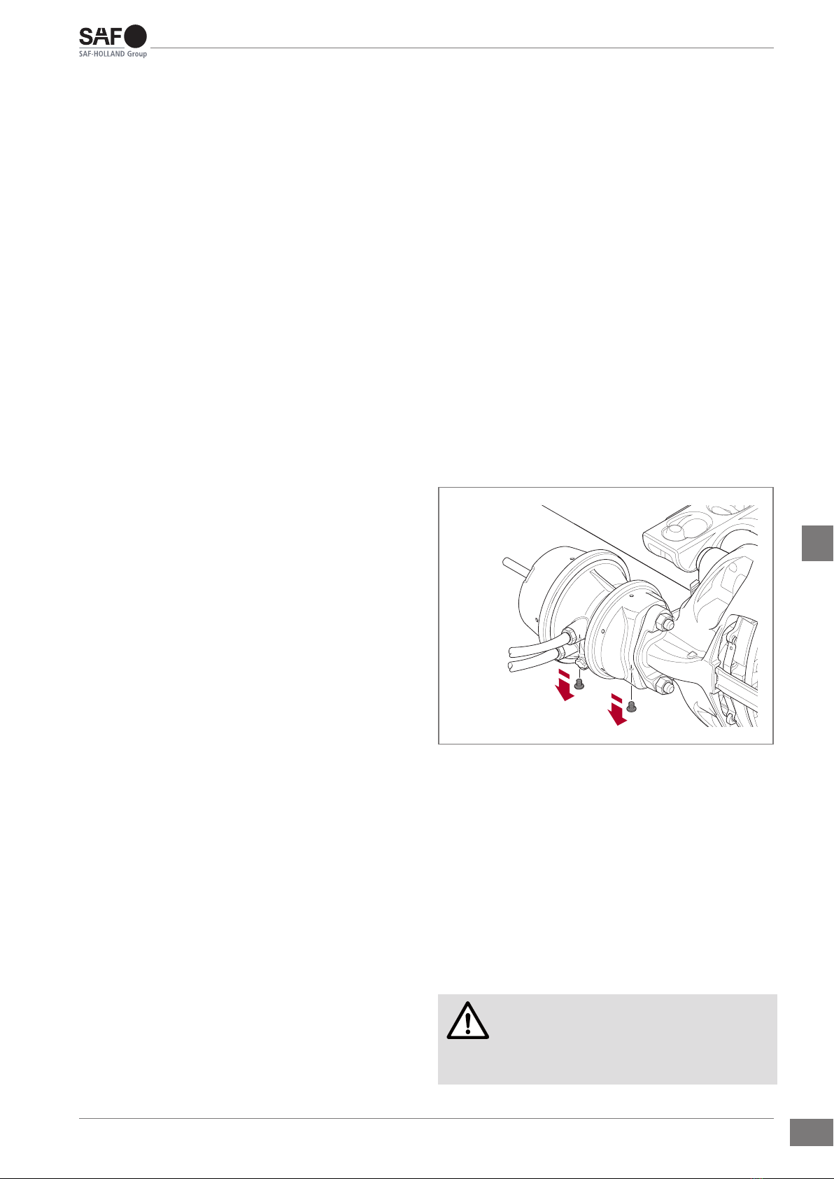
3.2.1 Lifting and supporting the vehicle
axle..................................................... 8
3.2.2 Removing the wheel........................... 9
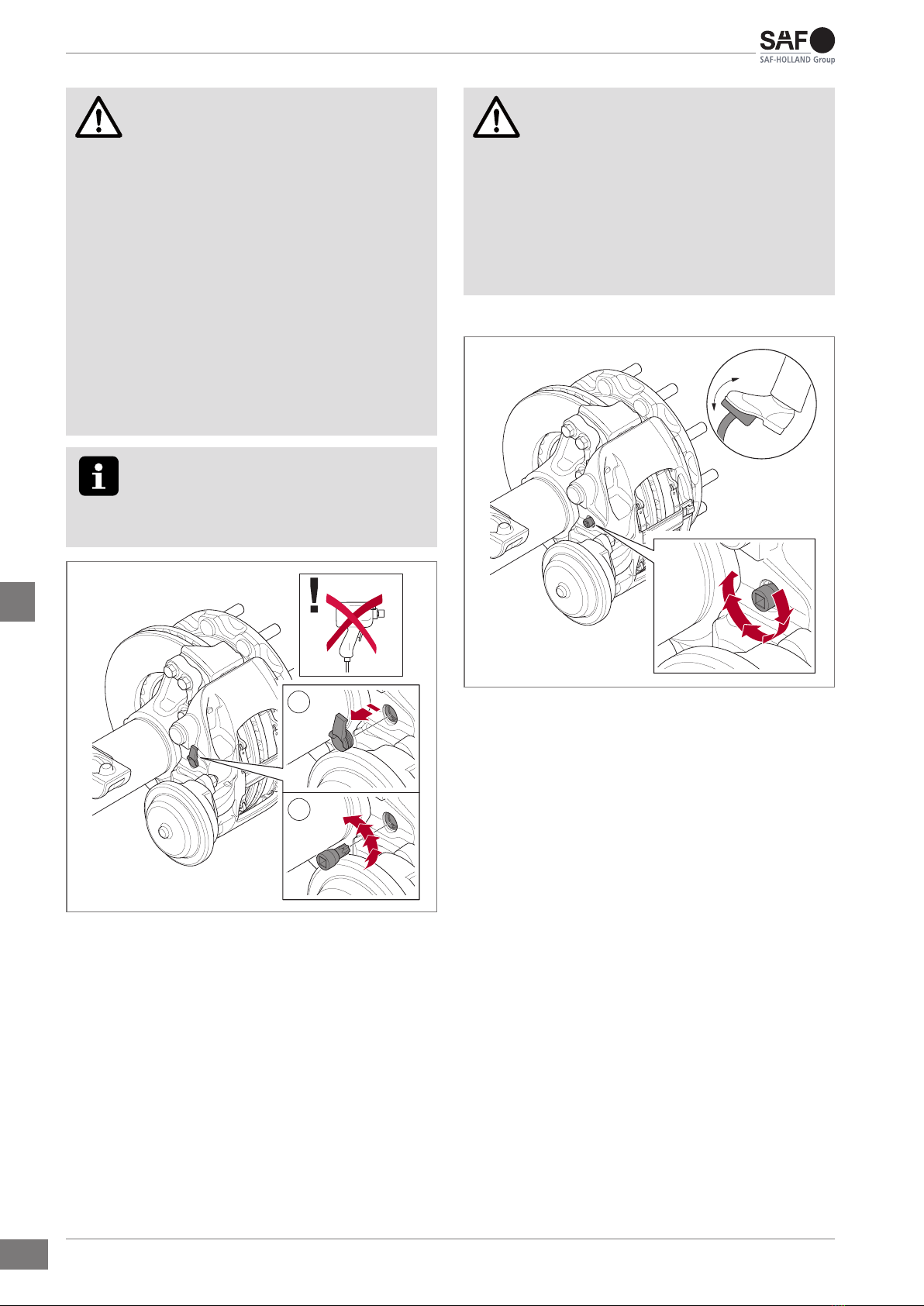
3.3 Function test.......................................... 9
3.3.1 Checking the adjustment unit............. 9
3.4 Final procedure ..................................... 11
3.4.1 Mounting the wheel ............................ 11
3.4.2 Lowering the vehicle axle................... 11
4 Inspection procedures................................. 13
4.1 General information............................... 13
4.2 Inspection intervals ............................... 13
4.3 Inspections ............................................ 14
4.3.1 Daily visual inspection........................ 14
4.3.2 Checking the overall condition ........... 14
4.3.3 Checking brake pad wear .................. 14
4.3.4 General brake pad clearance check .. 15
4.3.5 Checking the brake disc..................... 16
4.3.6 Plugs and protective caps check........ 16
4.3.7 Checking the thrust plate guide pins.. 17
4.3.8 Checking the actuation interface........ 18
4.3.9 Checking the guide pin bellows.......... 19
4.3.10 Checking the thrust plate bellows ...... 20
4.3.11 Checking the slide function ................ 21
4.3.12 Measuring the bearing clearance....... 21
5 Replacement procedure .............................. 23
5.1 General information............................... 23
5.2 Replacing the brake pads ..................... 23
5.2.1 Initial procedure.................................. 23
5.2.2 Removing the brake pads .................. 23
5.2.3 Installing the brake pads .................... 24
5.2.4 Final procedure .................................. 25
5.3 Replacing the brake chamber ............... 25
5.3.1 Initial procedure.................................. 25
5.3.2 Removing the brake chamber ............ 25
5.3.3 Installing the brake chamber.............. 26
5.3.4 Final procedure .................................. 27
5.4 Replacing the adjustment screw
bellows .................................................. 27
5.4.1 Initial procedure.................................. 27
5.4.2 Removing the adjustment screw
bellows ............................................... 27
5.4.3 Cleaning ............................................. 28
5.4.4 Final procedure .................................. 29
5.5 Replacing the slide function assembly .. 30
5.5.1 Initial procedure.................................. 30
5.5.2 Removing the slide function
assembly ............................................ 30
5.5.3 Cleaning ............................................. 32
5.5.4 Installing the slide function assembly. 32
5.5.5 Final procedure .................................. 35
5.6 Fully replacing the reset shaft ............... 35
5.6.1 Initial procedure.................................. 35
5.6.2 Fully removing the reset shaft ............ 35
5.6.3 Fully installing the reset shaft............. 35
5.6.4 Final procedure .................................. 36
5.7 Replacing the disc brake....................... 36
5.7.1 Initial procedure.................................. 36
5.7.2 Removing the disc brake.................... 36
5.7.3 Installing the disc brake...................... 36
5.7.4 Final procedure .................................. 37
6 Specications ............................................... 37
6.1 Wear limits............................................. 38
6.2 Tightening torques................................. 38
6.2.1 General .............................................. 38
6.2.2 SAF SBS 2220/SBS 1918 H0 ............ 38
Table of contents