SAF 3 434 3317 00 Reference manual

Page 1 of 6
3D Bush Removal and Replacement Guide Using a Hydraulic Bush
Service Tool
CONTENTS OF SAF 3D-BUSH HYDRAULIC KIT
21
3
4
Photo Item Description Part No.
1
Hydraulic Intra 3D Bush Tool Mounting Tool 3 434 3317 00
2
Hydraulic Intra 3D Bush Tool Actuator (Hydraulic Ram) 4 434 3302 00
3
Hydraulic Intra 3D Bush Tool Connecting Hose 4 434 3303 00
4
Hydraulic Intra 3D Bush Tool Pump 4 434 3304 00
SERVICE BULLETIN
PREPARATION
Prior to removing the pivot bushing, perform the following steps in accordance with the relevant operating
instructions and the associated repair and maintenance manual, observing the indicated safety instructions:
1. Place wheel cocks in front of and behind the trailer wheels to prevent the trailer from rolling
WARNING
Failure to use wheel chocks might allow the vehicle to roll which could result in death or serious injury.
2. Bleed all air from the air suspension system
3. Suitably support the axle
4. Remove the adjustable pivot bolt and discard along with the nuts
5. Remove the shock absorber from the trailing arm, and discard the nuts
6. Lower the axle
7. Replacement part numbers are:
4177303500K - 3D Bush and Installation Lubricant
RK2980 - 3D Bush, Installation Lubricant and Replacement Mounting Hardware

Page 2 of 6
Prior to removing the pivot bushing, assemble the removal
tool correctly.
For this purpose, assemble the components as shown
in
figure 2, Screw the Ram (3), Ram Adapter (8),
Ram Extension
(9) and Threaded Rod (4) together in that order, attach
the Cover Plate (7) over the Ram Extension, then slide the
Receiver Tube over (5) the Threaded Rod.
Fig. 2 - Assembled Removal Tool
! IMPORTANT
When assembling the removal tool, always make sure that
the receiver tube end (5) with out a centering ring faces
toward the cover plate. The centering ring(Fig.3) of the
receiver tube is used to center the receiver tube on the
trailing arm receptacle. When the removal tool is used, the
centering ring must always face toward the trailing arm
receptacle.
Fig. 3 - Receiver tube with centering ring
Centering
Ring
REMOVAL
Fig. 1 - Identification of removal tool components
Preparing the Pivot Bush
Replacement Tool
The pivot bushing removal tool (here after
abbreviated to removal tool) consists of:
(1) Enerpac hydraulic actuator
(2) Hydraulic connecting hose
(3) Hydraulic ram
(4) Threaded rod
(5) Receiver tube
(6) Drive nut
(7) Cover plate
(8) Ram adapter
(9) Ram extension
1
2
3
4
5
67
89

Page 3 of 6
Removing the Pivot Bushing
! IMPORTANT
The pivot bushings must always be replaced in pairs on an
axle. Always remove and replace one pivot bushing before
beginning to remove the second pivot bushing in order to
make sure that the pivot bushing that still has not been
removed is available as a reference point for adjusting the
spring center correctly.
To remove the pivot bushing, proceed as follows:
1. Identify the raised position locator (whitened in)
2. Using a white marker pen, draw a line (Fig. 5) on the
outside of the trailing arm receptacle at the raised
position locator of the pivot bushing. This line marks
the orientation of the existing pivot bushing within
the receptacle and will be used to properly orient the
replacement bushing during installation.
Fig. 4 - Raised bushing position locator
WARNING
Failure to properly install bushing will reduce vehicle
stability which could result in death or serious injury.
3. Lubricate the Drive nut (6) and the threads on the
threaded rod (4). Use standard grease.
4. Insert the threaded rod end (4) of the correctly pre-
assembled removal tool through the hole in the pivot
bushing until the centering ring of the receiver tube (5)
fits the bushing receptacle. Screw the drive nut (6) onto
the threaded rod of the removal tool until it goes no
further (Fig. 6).
Connect the Hydraulic Pump (1) to the Ram (3) using the
Connecting Hose (2).
5. Operate the Hydraulic pump until the drive nut (6) and
the pivot bushing are completely drawn into the receiver
tube (5). Fig 7.
6. Remove the removal tool from the trailing arm.
7. Continue to push the pivot bushing until it is forced
in to the widened section of the conical receiver tube (5)
from where it can be easily removed.
8. Clean out pieces of old bushing and any foreign
material left in the receptacle using a wire brush.
Fig. 5 - Marking the bushing orientation
Fig. 7 - Removal tool installation
Fig. 6 - Removal tool installation

Page 4 of 6
INSTALLATION
! IMPORTANT
The centering ring of the receiver tube is used to center the receiver tube on the trailing arm receptacle. When
the installation tool is used, the centering ring must always be positioned against the trailing arm receptacle.
Installing the Pivot Bushing
1. Lubricate the threads on the threaded rod (4).
2. Apply installation lubricant evenly to the internal
surface of the receptacle as illustrated in Fig. 8 and to
the external surface of the replacement pivot bushing as
shown in Fig. 9.
3. Use installation lubricant P-80 Emulsion.
WARNING
Failure to use proper lubricant during pivot bushing
installation could reduce vehicle stability which could
result in death or serious injury.
4. Insert the pivot bushing into the receiver tube end
opposite of the centering ring. Make sure that the pivot
bushing is properly aligned in the receiver tube using the
bushing position locator as a reference point (Fig. 10).
The bushing position locator of the replacement bushing
must be aligned with the line on the outside of the
receiver tube. The orientation index marked “Top” must
face upward as illustrated in Fig. 10. If need be, readjust
the pivot bushing.
5. Push the pivot bushing and the drive disc (6)
completely into the receiver tube as shown in Fig. 11.
Fig. 8 - Lubricated receptacle
Fig. 9 - Lubricated pivot bushing
Fig. 10 - Correctly aligned pivot bushing
Fig. 11 - Installing the drive disc
6. Insert the threaded rod (4) of the pre-assembled
installation tool from the wheel side through the
receptacle, making sure that the cover plate (4) is
positioned properly against the receptacle as illustrated
in Fig. 12.
7. Slide the receiver tube (5) over the exposed threaded
rod (4) with the centering ring of the receiver tube
facing toward the receptacle until the receiver tube rests
squarely on the receptacle. Fasten the drive nut ensuring
the drive plate is in place.
Make sure that the line previously drawn on the external
surface of the receptacle is aligned with the line on the
receiver tube.
Note: Use the same tool for installation.
Fig. 12 - Correct receiver tube position

Page 5 of 6
CAUTION
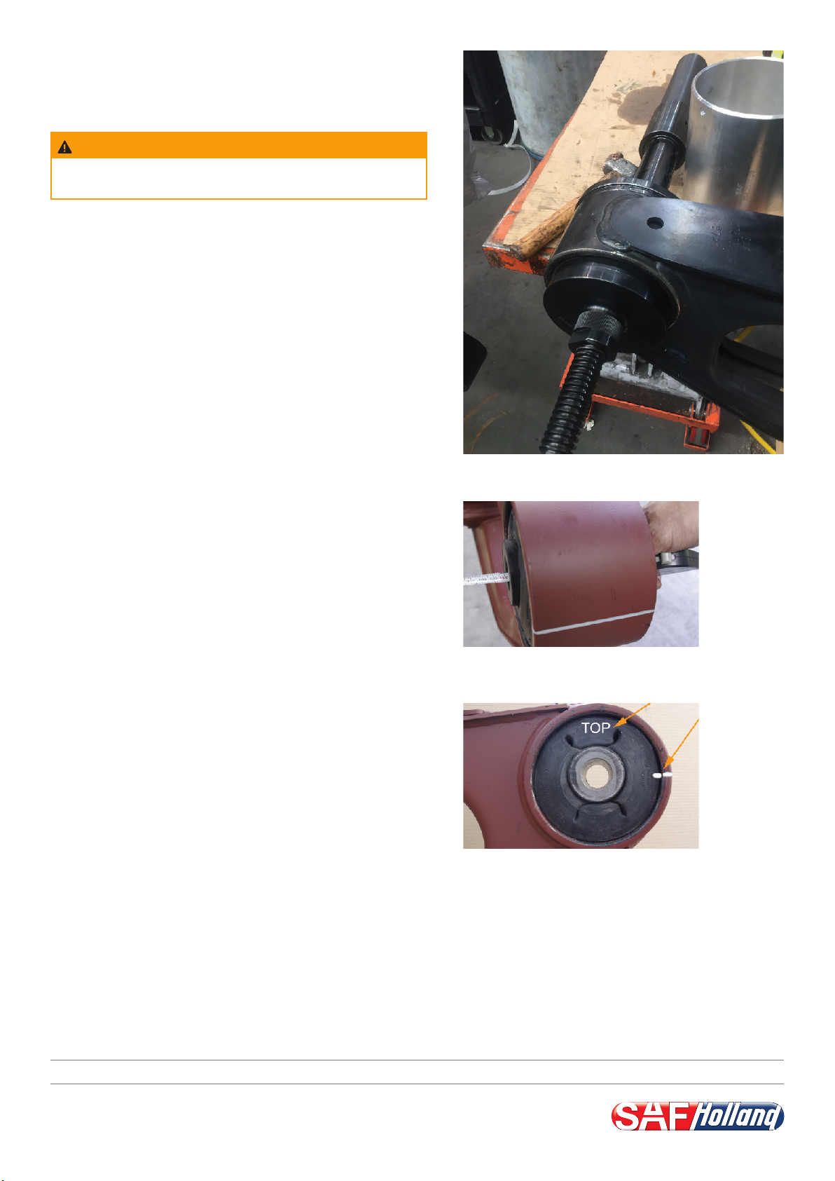
Failure to support loose receiver tube may allow it to fall,
resulting in minor injury or property damage.
Fig. 13 - Removed receiver tube
9. Remove the receiver tube and continue to operate the
hydraulic actuator until the pivot bushing is completely
drawn into the receptacle.
10. Disassemble and remove the installation tool.
11. Check the spring center and readjust as needed using
dead blow mallet.
Fig. 14 shows a spring center of 1300 mm, for example.
Dual tyre standard measurements:
940mm Intra disc
960 Intra drum
12. Check the proper orientation of the pivot bushing.
Make sure that the orientation index marked “TOP”
(in white colour for illustration purposes) faces upward
and that the bushing position locator of the replacement
bushing is aligned with the bushing orientation line
drawn on the outside of the receptacle
(Fig. 15). If the replacement pivot bushing is not installed
properly, remove and reinstall it.
Remove the pivot bushing on the opposite axle side as
described earlier and install a replacement pivot bushing
as outlined.
8. Operate the Hydraulic pump until the drive nut (6)
and the pivot bushing are completely drawn into the
receptacle (5) and the receiver tube becomes loose and
can be removed (Fig. 13).
Fig. 14 - Checking spring center
Fig. 15 - Checking installation position
FINAL STEPS
Upon replacement of the pivot bushing, perform the
following final steps in compliance with the relevant
operating instructions and the associated repair and
maintenance manual. Observe the relevant safety
instructions and the specified tightening torques:
1. Lift the axle ensuring new wear mounts are installed.
2. Install and slightly tighten new pivot bolts and nuts.
3. Install the shock absorber using new nuts.
4. Remove the axle supports.
5. Apply air pressure to the air suspension system.
6. Remove the wheel chocks.
7. Adjust the ride height.
8. Check the axle alignment of the trailer.
9. Tighten the pivot bolt, referring to the appropriate
tightening instructions and specifications on the
following page.
SAF-HOLLAND (Aust.) Pty. Ltd. · www.safholland.com.au
Group

Tightening instructions for adjustable pivot bolt
Attention:
• Tighten only within the specified ride height
range!
• No paint residues between eccentric/thrust
washer and hanger!
• Bolt head always on the eccentric washer side
and to the outside of the trailer
Pretightening: 400 Nm
Use Torque wrench
Angle tightening: 120°
Use impact wrench or extend lever to 2.5m
Tightening torques SAF INTRA with steel
hanger bracket
NOT MAINTENANCE-FREE!
• Pivot Bolt and Nut to be used only once
• Threads not to be oiled or greased!
• Shock absorber nuts to be used only once
• Service intervals for aluminum hanger brackets and
stainless steel hanger brackets: first check after 500km,
further check after every 6 months.
• Service Intervals for Steel Hanger Brackets:
- First check after 5000kms
- Further checks every 12 months
• Pivot bolt: Inspection torque 1,200 Nm
Shock absorber bolt: Inspection torque 600 Nm
Tightening torques for SAF air suspension systems
M12 (SW19)
40 Nm
M16 (SW24)
180 Nm for steel plunger piston
80 Nm for plastic plunger piston
M30 (SW46)
400Nm+120o
Tightening torques SAF INTRA with aluminum
hanger bracket and stainless steel hanger bracket
M20x1,5 (SW30)
400 Nm
M30 (SW46)
400 Nm + 120o
M20x1,5 (SW30)
600 Nm
M12 (SW19)
40 Nm
M16 (SW24)
180 Nm for steel plunger piston
80 Nm for plastic plunger piston
M20x1,5 (SW30)
600 Nm
Attention!
• Check torque settings after the first 5000kms
for steel hangers
• For aluminum and stainless steel hangers check
the torque settings after 500KMS
• Do not reuse pivot bolt and nut
• Do not oil or grease threads
Page 6 of 6
Visual inspection
Marking for angle tightening
This manual suits for next models
3
Table of contents
Popular Tools manuals by other brands

BGS technic
BGS technic 6774 instruction manual

Omer
Omer HR23 S5 Use, maintenance and spare parts manual

Triton
Triton SJA420 Operating and safety instructions

Volpi
Volpi Kamikaze KV4 user manual

Steelman
Steelman 46462 Operator's manual

Alpha Professional Tools
Alpha Professional Tools CCP005 Technical notes