© Rear View Safety | All rights reserved p. 3
Introduction to Calibration
The calibration process “stitches” together images from the front, back, left, and right camera views into a 360 top-level
image of the space around the vehicle. After the physical installation of the cameras, ECU, antennas, push buttons, and
optional monitor/recorder, the inView 360 HD AVM system will have to be calibrated to optimize this 360° view. This requires
someone who is comfortable installing and conguring software. In addition to the calibration procedure, this process
requires that person to do the following:
• You will need to place calibration pads so that they can be viewed without obstruction.
• You will need to “take” images via the vehicle cameras for use during calibration.
• You will need to unzip, copy, and launch the calibration tool on a PC.
• You will need to transfer image les from the inView 360 HD AVM system to your Windows PC.
• You will need to save the calibration le to the USB memory device, and upload it to the ECU.
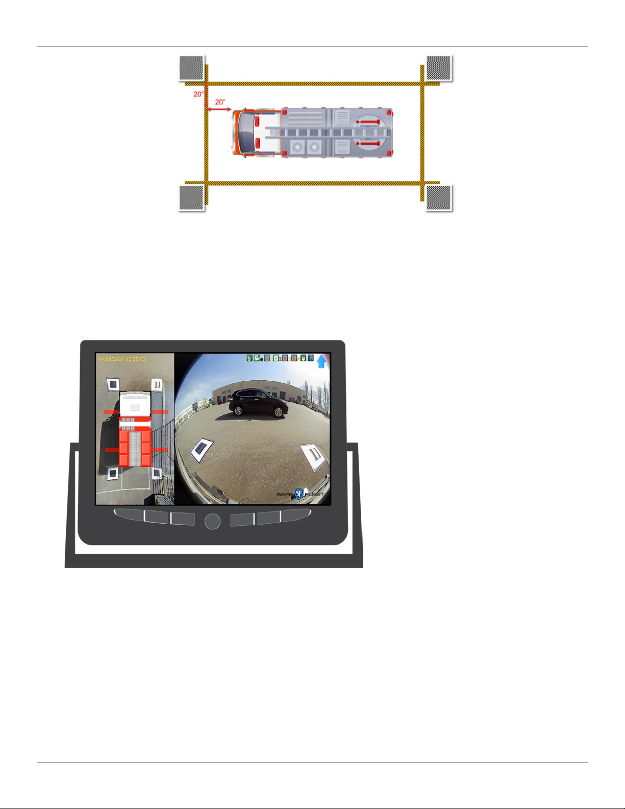
Placing Calibration Pads
Calibration pads provide reference points for the cameras during the software calibration process. Therefore, it is important
that the calibration pads are accurately and optimally placed�
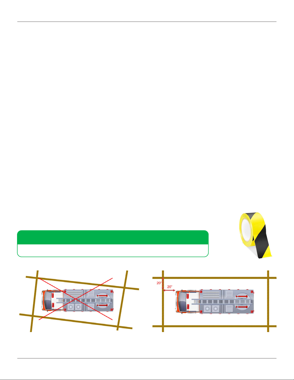
Using the roll of police-type tape provided with the inView 360 HD AVM system kit, create a rectangular
perimeter around the vehicle, ensuring that you use perpendicular (90 degree) angles at each corner.
TIP!
Calibration pads need to be placed at least 20 inches away from all sides of the vehicle.
Incorrect Tape Placement Correct Tape Placement
Calibration Kit Components
1 x a set of four (4) calibration pads
1 x USB memory drive that contains the Calibration Tool. (NOTE: This memory drive can be used for transferring the camera
images from/to the ECU to your PC.)