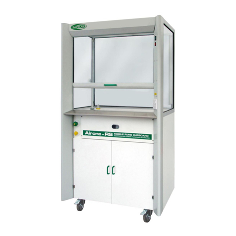
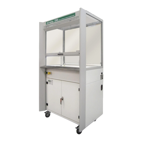
Safelab Airone 1000RS/E User manual

DOCUMENT NO: M37 ISSUE NO: 02 ISSUE DATE: 01/11/2015
1
INSTRUCTION MANUAL
Mobile Airone 1000RS/E
Filtration Fume Cupboard
SAFELAB SYSTEMS
Airone Building ● 8 Beaufighter Road ● Weston-Super-Mare ● BS24 8EE
WWW.SAFELAB.CO.UK

DOCUMENT NO: M37 ISSUE NO: 02 ISSUE DATE: 01/11/2015
2
Contents
Page 2 Contents.
Page 3 Foreword.
Page 4 Principles of Operation.
Page 5 Installation and Assembly Instructions.
Page 6 & 7 Specification.
Page 8 Chemical List.
Page 9 &10 Operating Instructions.
Page 11 Wiring Diagram.
Page 12 Calibration.
Page 13,14,15 & 16 Maintenance and Performance Monitoring.
Page 17 Pre-filter Replacement.
Page 17 Main Filter Replacement.
Page 18 Spare Parts.
Page 18 Troubleshooting.
Page 19 E. C. Declaration of Conformity.

DOCUMENT NO: M37 ISSUE NO: 02 ISSUE DATE: 01/11/2015
3
FOREWORD
This manual has been prepared to give guidance and information to ensure optimum
operation of the Mobile Airone 1000RS/E Filtration Fume Cupboard.
It is recommended that service and maintenance operations should only be undertaken by
SAFELAB Service Engineers or their authorised agents.
Details of Service Contracts/Programmes, along with information on these and other
products are available on request from:
SAFELAB SYSTEMS LTD.
Airone Building
8 Beaufighter Road
Weston-Super-Mare
BS24 8EE
Telephone - 01934 421340
Fax - 01934 641569
E-mail - safelab@safelab.co.uk
Website: - http://www.safelab.co.uk
NOTE:
This Mobile Airone 1000RS/E Filtration Fume Cupboard requires annual service and
inspection under the requirements of COSHH regulation 9 by a suitably qualified
engineer.

DOCUMENT NO: M37 ISSUE NO: 02 ISSUE DATE: 01/11/2015
4
PRINCIPLES OF OPERATION
Air is drawn into the cupboard at the working aperture Abelow the sliding sash at a
velocity high enough to ensure entrainment of any fumes/odours given off by the
processes carried out within the cupboard.
The fumes from within the cupboard are carried by the moving body of air through the
cupboard Bto the pre-filter Cand main filter Dto absorb vapours and other noxious
fumes/odours before being expelled by the exhaust fan Eas clean air F.
The fan E, which is mounted below the main filter exerts a negative pressure on the
internal space within the cupboard B. This in turn pulls external air into the cabinet through
the working aperture Aand keeps a constant circulation of pre-filtered clean air passing
through the cupboard whilst ensuring that noxious odours are trapped and adsorbed by
the main filter.

DOCUMENT NO: M37 ISSUE NO: 02 ISSUE DATE: 01/11/2015
5
INSTALLATION AND ASSEMBLY INSTRUCTIONS
Contents of Packaging (as standard):
-Filtrete pre-filter. - Operational manual
-Main filter. - Quality Pass.
-Allen key - Service and Maintenance Letter.
-Mains power lead - Conformity certificates
-Safety Log Book. - Warranty form.
1. Remove outer packaging.
2. Remove filter housing cover panel with the allen key provided, to expose the main
filter and pre-filter chamber. Remove the card mounted pre-filter from within the
chamber.
3. Remove the main filter from the storage area at the base of the cupboard.
Before lifting the main filter please note it weighs approx. 22kg and may
require two people to safely handle it.
Unpack the main filter and slide the filter, gasket side down, between the support
guides in the filter chamber and ensure that it is pushed fully to the back. Tighten
the two filter clamp knobs evenly.
4. Fill in the date on the filter identification label and stick it on the front of the filter
ensuring it will be clearly visible through the window in the front of the filter housing
cover panel.
5. Place the card mounted pre-filter on the top of the main filter with the tab facing
outwards.
6. Replace the filter housing cover panel.
7. Following this procedure it is recommended that the filter monitoring procedure
detailed in the Operational Safety Manual is performed. This ensures correct seating
of the filter within the cabinet.
Written records of filter monitoring are a legal requirement under COSHH.
8. Connect to the power supply and the cabinet is ready for commissioning.
See Calibration instructions on page 12.
Services:
Provision has to be made for connecting the fume cupboard services, either via a docking
station or plumbed in gas, water and waste. Also a tethering point is required.
Water coupling –1/4” BSP male threaded outlet required.
Gas coupling –1/8” BSP male threaded outlet required.
Waste - 38mm Vulcathene mechanical waste fitting (the fitting should be blanked of when
not in use, with a type W24 blanking plug and W231 38mm nut.

DOCUMENT NO: M37 ISSUE NO: 02 ISSUE DATE: 01/11/2015
6
SPECIFICATION
Definition: The Airone 1000RS/E Mobile Filtration Fume Cupboard has been designed
to comply with BS7989:2001 for filtration fume cupboards along with
Building Bulletin 88 from the Department for Education and Employment and
has been tested by CLEAPSS.
Application: The unit gives maximum flexibility and can be manoeuvred between
different locations. A counterweighted sliding front sash and clear laminated
glass sides and rear provide 360° all round visibility making this ideal for
demonstrations. Lowering the sash will reduce the airflow and therefore
noise is reduced to a minimum benefiting demonstration.
Construction: Aluminium extrusions and mild steel sheet, welded and painted in epoxy
powder coat, Light Grey RAL-7035 and White RAL-9016. The fume
enclosure is laminated safety glass.
The top panel and rear baffle are clear acrylic.
The suspended/counterweighted front sash is in laminated safety glass with
an epoxy powder coated extruded aluminium handle.
The work tray is white polypropylene as standard.
Sash Operation: The vertical sliding laminated glass sash of the AIRONE 1000RS/E fume
cupboard is suspended and counterweighted providing added advantages
over fixed-sash or folding sash fume-hoods. E.g. the sliding laminated glass
sash can be closed and this provides protection to operators.
The vertical sash conforms to Paragraph 4.12 of the Building Bulletin # 88 of
the DofEE (Rev. of Design Note # 29) and BS:7258 requirements in that the
sash cannot fall if one of the suspending cable-cords is cut.
Moving the vertical sash upwards and downwards causes the fan to speed
up or slow down to give a constant face velocity, this is controlled by a micro
switch.
Filter Housing: The filter housing is located above the lower cabinet doors and contains the
main filter and pre-filter.
Storage Area: Located at the bottom of the unit and accessible by hinged doors with
magnetic catches.
VAV System: The unit has a VAV (Variable Air Volume) system incorporating a filter
saturation alarm. The VAV system ensures that the inflow is constant at
variable sash heights. The control panel is located on the RH side cabinet
aerofoil.
ON/OFF Switch: Illuminated green, and located on the RH side cabinet aerofoil above the
electronic VAV control panel.
Supply: 230V 50Hz - 0.9 A (excluding electric socket load).
Performance: The average inflow at the working aperture is 0.4 m/s.
The minimum working aperture is 200mm high.
The maximum working aperture is 365mm high.
Noise level: 59 dBA

DOCUMENT NO: M37 ISSUE NO: 02 ISSUE DATE: 01/11/2015
7
Services: Gas, water with remote valves with flexible connection hoses and waste with
bottle trap and flexible drainpipe (unless specified otherwise)
SPECIFICATION (CONTINUED)
Pre-filter: One piece cardboard framed blended synthetic fibre with polypropylene spun-
bonded scrim –Safelab code: 101297 pack of 12 (the pre-filter will require
replacing a minimum of every three months).
Main filter. CMS schools impregnated/activated carbon filter - Safelab code: 101094,
Weight: 22 kg subject to humidity. See chemical list –page 8.
Dimensions: External: 1000mm wide x 700mm deep x 1850mm high.
Internal (Fume Hood Enclosure): 950mm wide x 500mm deep x 865mm high.
Max. Sash Opening in Operation: 840mm wide x 365mm high.
Max. Sash Opening for Loading: 840mm wide x 600mm high.
Weight (packed): 125kgs (including carbon filter).
SPECIFICATION DIAGRAM
1) Lower storage area.
2) Filter access panel/viewing window.
3) Vertical laminated glass sash.
4) Laminated glass side & rear windows.
5) Clear acrylic top panel.
6) Main filter.
7) Pre-filter.
8) Exhaust fan.
9) Castors (locking at front).
10) Gas valve (yellow).
11) Water valve (green).
12) Electrical access panel.
13) 13A electric socket.
14) VAV system control panel.
15) Illuminated ON/OFF switch (green).
16) Flexible service pipes and tether.
17) Services aperture (both sides).
18) Mains lead with moulded plug.
19) Airflow sensor cover.

DOCUMENT NO: M37 ISSUE NO: 02 ISSUE DATE: 01/11/2015
8
CHEMICALS WHICH ARE SUITABLE FOR USE WITH THE SAFELAB CMS
(EDUCATION) CARBON FILTER:
Inorganic
Aluminium Chloride and Bromide Ammonia
Ammonia Chloride Bromine Chlorine
Chromium (VI) Dichloride Dioxide (Chromyl Chloride)
Hydrochloric Acid vapour Hydrogen Chloride
Hydrogen Sulphide Iodine
Iodine Chlorides Lead fumes
Lead Bromide fumes Mercury and its compounds
Nitric Acid vapour Nitrogen Oxides (acidic)
Phosphine Phosphorus (white)
Phosphorus Chlorides and Bromides Phosphorus Oxides
Silicon Tetrachloride Sulphur Dioxide
Thionyl Chloride Tin (IV) Chloride
Titanium Tetrachloride Zinc Chloride fumes
Organic
Acid Amides Acid Anhydrides
Acid Chlorides Alcohols
Aldehydes Aliphatic Amines and their
salts
Aliphatic Hydrocarbons Aromatic Amines and their
salts
Aromatic Hydrocarbons Aromatic Nitro compounds
Carboxylic Acids Esters
Ethers Ketones
Nitriles Organo Halogens
Phenols Pyridine
Dusts etc
Dyes
Enzymes
Smoke

DOCUMENT NO: M37 ISSUE NO: 02 ISSUE DATE: 01/11/2015
9
OPERATING INSTRUCTIONS
1. Position the Airone RS/E mobile fume cupboard where it is to be used and lock the
front castors (see page 10 for a guide to positioning the fume cupboard).
2. Clip wire tether to anchor point before inserting mains plug into a13A electric socket
3. Connect flexible gas, water and waste pipes to the plumbed in fittings or docking
station ensuring that the gas and water fittings are securely pushed home and that
the waste coupling is screwed on tightly. The services can be connected at either
side of the cupboard (see photo at bottom of page).
2. Switch on at the mains socket and the green ON/OFF switch on the cupboard and
allow it to run for approximately 5 minutes prior to use.
3. Always use appropriate PPE (personal protection equipment) when using the
Airone RS Mobile Fume Cupboard.
4. When working in the cupboard try and ensure that the sliding sash is in its lowest
position, and always lower the sash when the fume cupboard is not in use.
5. If using Bunsen burners, place them at least 20cm from the front sash, sides or rear
baffle.
6. Before switching off the cabinet after use allow it to run for a further 5 to 10 minutes
to make sure all hazardous vapours or gasses have cleared, and check that any
bottle are capped or stoppered and no material has been left on the necks or
pooled around the bases.
Good housekeeping is essential to prolong carbon filter life.
7. After use, always run cold water through the waste system, and prior to
disconnection, raise the flexible waste pipe to make sure there is no water trapped
in the pipe.
8. Disconnect water, gas and waste hoses, then unclip the tether and return the fume
cupboard to its storage location. If used with a docking station, always replace the
cap on its waste fitting after use.

DOCUMENT NO: M37 ISSUE NO: 02 ISSUE DATE: 01/11/2015
10
Services on LH side Services on RH side
OPERATING INSTRUCTIONS (CONTINUED)
GUIDE TO POSITIONING LOCATIONS FOR THE AIRONE RS MOBILE FUME CUPBOARD

DOCUMENT NO: M37 ISSUE NO: 02 ISSUE DATE: 01/11/2015
11
WIRING DIAGRAM

DOCUMENT NO: M37 ISSUE NO: 02 ISSUE DATE: 01/11/2015
12
CALIBRATION
(SHOULD ONLY BE UNDERTAKEN BY A SUITABLY QUALIFIED PERSON)
Digital Control Panel -
1. Switch on the unit using the green rocker switch and allow it to run for a minimum of
fifteen minutes.
2. Switch off the unit and switch it back on again straight away while holding in the “CAL”
button on the digital control panel membrane.
3. Release the “CAL” button when two audio beeps are heard.
4. After releasing the “CAL” button, another audio beep will sound and a “SET FAN SPEED”
prompt message will appear on the LCD display.
5. Raise the sash to its highest working position at the upper sash stop (365mm), and using a
calibrated 100mm diameter vane anemometer, set the face velocity airflow at the sash
opening to the required level using the “FAN UP” & “FAN DOWN” buttons to alter the fan
speed.
6. When the required face velocity has been set and allowed to stabilise, press the “CAL”
switch again, and an airflow display in M/S (metres per second) will appear on the LCD
display.
7. After the airflow reading has stabilised, use the “FAN UP” & “FAN DOWN” switches to set
the displayed airflow to match the calibrated handheld anemometer.
8. When the desired reading is observed press the “CAL” switch once, the audio will beep
twice and the fan & alarm LED will alternate on and off for approximately six seconds
during which time the airflow and saturation alarm settings are being stored.
NOTE: The filter saturation alarm function is disabled for 5 minutes from initial power up, during
this period no text is displayed. When enabled, FILTER OK is displayed. If no filter saturation
alarm is fitted, no text is displayed after the 5 minute warm up period.
If the filter saturation alarm system detects a saturation condition of the filter, the FILTER OK text
changes to FILTER SATURATED, the alarm text flashes every second and an audio alarm
sounds. This can be muted using the alarm mute switch on the membrane panel.

DOCUMENT NO: M37 ISSUE NO: 02 ISSUE DATE: 01/11/2015
13
MAINTAINANCE AND PERFORMANCE MONITORING:
This fume cupboard is a ‘portable appliance’, powered by mains electricity and it complies with EN-
BS-61010. The correct fuse (10A) must be fitted to the mains plug and this and other exposed
parts of the electrical system should be examined frequently for obvious damage. There should be
regular formal inspections including earth bonding and insulation testing.
Your Airone 1000 RS/E Mobile Fume Cupboard should have an annual service by a suitably
qualified person, to maintain it’s good condidtion and reduce the possibility of hazard to the
operator.
We recommend that a service programme be arranged with Safelab Systems ltd.
Regular maintenance by our qualified personnel will ensure safe running of your equipment
and also ensure that you meet your requirements under COSHH regulation 9.
The minimum requirement to comply with COSHH Regulations is that the face velocities and filter
efficiencies must be monitored (at least once every 14 months) and a written record kept of the
results. Tables printed on the back pages of the Operational Safety Log-Book are suitable for
keeping these records.
Refer to page 14 for face velocity and filter checking procedures.
It is also recommended that the pre-filter be replaced a minimum of once every 3 months.
Safelab Systems offer Service Contracts for regular filter-monitoring and servicing of all AIRONE
Filtration Fume Cupboards. Please phone our Service Department for details. Tel. No. 01934
421342
Safelab Systems recommend that a simple air sampling test be carried out once a week at eye
and mouth level and/or at the outflow port of the AIRONE Fume Cupboard utilising an appropriate
GASTEC Chemical Detector Tube (available from Safelab Systems). Record result in the
Operational Safety Log-Book.
Information for users for Easy Do-It-Yourself filter-monitoring checks:
Equipment Needed:
A calibrated vane anemometer with a diameter of 100mm and the facility to average readings over
a period of 10 seconds.
Unidirectional Hot-wire Anemometers are also available with the facility of averaging readings.
Refer to Building Bulletin # 88 of the DfEE (rev. of Design Note #29)
GASTEC Volumetric Gas-Detection kit consisting of a disposable tube used with a volumetric
detector hand pump that draws a measured volume of air through the tube. The length of colour
change in the tube indicates the concentration of the gas tested. SAFELAB SYSTEMS supply a
suitable model:
GASTEC Volumetric Detector Pump (Safelab code SRV604).
Additionally packs of disposable tubes will be required.
Pack of 10 Sulphur Dioxide Tubes, 1 pack of 10 Trichloroethene. Tubes.
Refer to Operational Safety Log-Book and Chemical Listing for correct selection from over 500
different GASTEC chemical detector tubes available for measuring ppm concentration levels of
over 800 compounds in gaseous phase.

DOCUMENT NO: M37 ISSUE NO: 02 ISSUE DATE: 01/11/2015
14
MAINTAINANCE AND PERFORMANCE MONITORING (CONTINUED):
INSTRUCTIONS FOR FACE VELOCITY MEASUREMENTS
(Record results on record form - page 15 )
PROCEDURE:
Imagine the face of the fume cupboard divided into
nine cells.
Stand as far as practicable from the fume
cupboard with the sensing head in the plane of the
sash and take airflow readings at approximately
the centres of each of the nine cells.
Record for each cell the approximate average reading over a period of at least ten
seconds, applying any corrections from the air flow meter calibration chart.
Look at the table and repeat any reading which seems to be very different from the
general pattern. Record the average of this and the previous reading.
CALCULATION:
Minimum face velocity -
Record which of a, b,c,d,e,f,g,h,i, is the smallest, i.e.: the minimum face velocity.
If it is below 0.3 m/s then containment factors are impaired and the cause will have to be
found and remedied.
VARIATION:
Check for variation as follows :
Add together the values a,b,c,d,e,f,g,h,i and divide by 9 to get the average.
Find the biggest and smallest of a,b,c,d,e,f,g,h,i.
The upper percentage variation is the biggest minus the average, divided by the
average and multiplied by 100.
The lower percentage variation is the average minus the smallest, divided by the average
and multiplied by 100. Each of these should be below 30%, if not, then the Airone 1000RS
has been parked in an unsuitable site and will have to be moved. (see page 10 for siting
guidance.)

DOCUMENT NO: M37 ISSUE NO: 02 ISSUE DATE: 01/11/2015
15
MAINTAINANCE AND PERFORMANCE MONITORING (CONTINUED):
AIRONE 1000RS EXAMINATION RECORD:
Site:.....................................................................................
......................................................
Location of Airone 1000RS:
............................................................................................
...……………………………………………
Air flow meter: ..................................................
used
Date
Of
Check
Readings in each of the cells as
above.
Average
( m/s )
Drop
>
10%
from
Do
filters
PASS
Is
Fume
flow
Any deterioration or
damage observed.
Fail if face velocity
Initials
of
Tester
a
b
c
d
e
f
g
h
i
Before
Check
Inward
< 0 . 3 m / s
If a drop of 10% is found then the cause of the problem should be cleared. (Check Prefilters.)
If the minimum face velocity is below 0.3 m / s then airflow in the fume cupboard is inadequate.

DOCUMENT NO: M37 ISSUE NO: 02 ISSUE DATE: 01/11/2015
16
MAINTAINANCE AND PERFORMANCE MONITORING (CONTINUED):
INSTRUCTIONS FOR FILTER SATURATION TESTING.
Regular filter checks and monitoring (once a week is recommended) to test quality of the
air breathed in by operators and filtration efficiency. Filter challenge tests can be carried
out during routine Service and Maintenance procedures once every 6 months as
described in the Operational Safety Log Book.
The recommended procedure for testing the efficiency of the system requires a GASTEC
Volumetric Detector Pump and Gastec Chemical Detector Tubes. Test the quality of air by
sampling at eye and mouth level at regular intervals once a week with Gastec tubes
calibrated for the particular compound in concentrations below its respective OEL
(Occupational Exposure Limit) MEL (Maximum Exposure Limit) or OES (Occupational
Exposure Standard (or MAK in Germany and/or TLV in the USA).
Please refer to the Chemical Listing, Adsorption Index and Gastec Detection Guide
published in our Operational Safety Log-Book.
CLEANING
The materials used to construct the Airone 1000RS/E Mobile Fume Cupboard have been
selected to give maximum durability and a long life. It is beneficial however to regularly
clean and decontaminate the internal and external surfaces.
It is recommended that the cabinet is switched on during any cleaning procedure and that
suitable protective clothing (face-mask, gloves and safety glasses) is worn.
All surfaces should be cleaned with a mild detergent solution then finished off with a damp
cloth and wiped dry.

DOCUMENT NO: M37 ISSUE NO: 02 ISSUE DATE: 01/11/2015
17
FILTER REPLACEMENT
DURING THE PRE-FILTER AND MAIN FILTER REPLACEMENT PROCEDURE, SUITABLE PROTECTIVE
CLOTHING (FACE-MASK, GLOVES AND SAFETY GLASSES) MUST BE WORN
PRE-FILTER REPLACEMENT
(SAFELAB RECOMMENDS THAT THE PRE-FILTER IS REPLACED EVERY THREE MONTHS)
1. Switch off the cabinet and disconnect it from the mains electricity supply.
2. Remove the filter access panel (item 2 in page 7) to expose the filter enclosure.
3. Withdraw the pre-filter from the top of the main filter. Seal the old pre-filter into a polythene bag for
disposal.
5. Carefully slide the new pre-filter in to place above the main filter with the tab facing outwards.
6. Replace the filter access panel.
MAIN FILTER REPLACEMENT
(SAFELAB RECOMMENDS THAT THE MAIN FILTER IS REPLACED EVERY FIVE YEARS
DEPENDING ON USE AND APPLICATION)
1. Switch off the cabinet and disconnect it from the mains electricity supply.
2. Remove the filter access panel (item 2 in page 7) to expose the filter enclosure.
3. Remove the pre-filter from the top of the main filter, and unscrew the filter clamping knobs on each
side of the filter.
4. Check that the new or replacement Safelab carbon filter is correctly selected (consult Safelab Ltd by
phone, fax or e-mail for assistance).
5. Unpack the Main filter and prepare suitable equipment for its safe handling. Place the filter gasket
side upwards on a clean flat surface (Retain the packaging for disposing of the old filter).
6. Before removing the main filter please note it weighs approx. 22kg and may require two
people to safely remove it from the housing.
Firmly grip each side of the main filter, pull up to break seal, and withdraw it from the filter housing.
7. With the gasket side downwards, slide the new filter into place between the guides in the main filter
housing ensuring that it’s located fully to the back stop and evenly retighten the two knurled knobs to
clamp the filter in position, and fit a new pre-filter. Good filter seating is essential for effective
filtration.
8. Fill in the date on the filter identification label and stick it on the front of the filter ensuring it will be
clearly visible through the window in the front of the filter access panel.
9. Replace the filter access panel.
10. Reconnect to the mains electricity supply and switch on the cabinet.
11. Enter details of main filter change in the Safety Log Book.
12. Following this procedure it is recommended that the filter monitoring procedure detailed in the
Operational Safety Manual is performed. This ensures correct seating of the filter within the cabinet.
Written records of filter monitoring are a legal requirement under COSHH.

DOCUMENT NO: M37 ISSUE NO: 02 ISSUE DATE: 01/11/2015
18
SPARE-PARTS
Main filter: Part No. 101094
Pre-filters: Part No. 101297 (pack of 12)
Mains lead: Part No. 050201
Water hose (to supply): Part No. 170600
Water hose (valve to outlet): Part No. 170603
Gas hose (to supply): Part No. 170601
Gas hose (valve to outlet): Part No. 180604
Flexible waste pipe: Part No. 170500
Fan (2 fitted) Part No. 060250
On/Off switch Part No. 050245
Digital display PCB: Part No. 040250
Sash cord kit Part No. 000013
13A electric socket Part No. 050310
TROUBLESHOOTING
1. What if I can smell the vapours or gases being used in the procedure?
Filters have a high efficiency but, because the nose is very sensitive, the residual gases
passing through the filter may sometimes be smelt, even though their level is not
hazardous. If the gases are causing distress, the operation should be finished and the
degree of filter saturation monitored.
2. What if I can smell the vapours or gases being used in the procedure,
but I have checked the filter performance and it is satisfactory ?
Check siting of the cabinet to ensure that nothing is being allowed to escape out through
the sash. Fume containment is easily impaired by draughts from windows, doors or fan
heaters and air vents.
3. What if there is a release that the filters of the Airone 1000RS cannot contain?
If the initial chemical hazard analysis or risk assessment (under COSHH) has been carried
out correctly resulting in correct selection of appropriate types of carbon filters followed by
weekly air sampling and filter monitoring checks this is unlikely to occur. In case it does
happen, due to accidental release of gas or vapour or an unexpected spillage, then leave
the fan running and evacuate the area. Subject to the hazard assessment and local
considerations, it may be that personnel with breathing apparatus would have to return to
open windows and ensure that all hazardous vapours or gases had been dispersed.
It is recommended that a replacement carbon filter is kept available at short notice for such
an event.
WARNING:
If a spill exceeds the capabilities of the Airone 1000RS/E, it is likely to exceed the
capabilities of carbon filtration face masks. This means that only an air or oxygen cylinder
based breathing apparatus could provide adequate protection.

Table of contents
Other Safelab Laboratory Equipment manuals