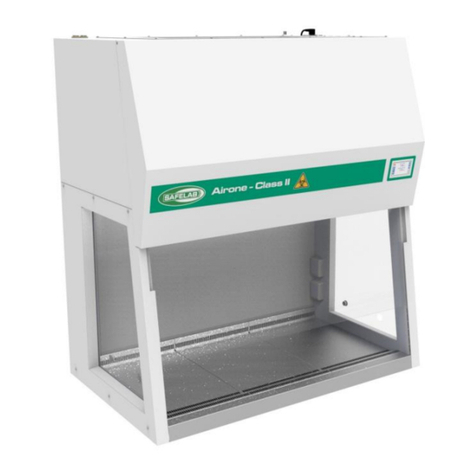
Safelab Airone X Series User manual

DOCUMENT N°: M17 ISSUE NO: 08 25/04/2018
INSTRUCTION MANUAL
Airone X Range of
Ducted Fume Cupboards
SAFELAB SYSTEMS LTD
Airone Building ● 8 Beaufighter Road ● Weston-Super-Mare ● BS24 8EE
Telephone: 01934 421340 •Fax: 01934 641569 •E-mail: safelab@safelab.co.uk
WWW.SAFELAB.CO.UK

DOCUMENT N°: M17 ISSUE NO: 08 25/04/2018
2
Contents
Page 2 Contents.
Page 3 Foreword.
Page 4 Principles of Operation.
Page 5 Installation & Assembly Instructions.
Page 6 Installation & Assembly Instructions (continued).
Page 7 Specification.
Page 8 Specification (continued).
Page 9 Specification Diagram.
Page 10 Operating Instructions.
Page 11 Wiring Diagram.
Page 12 Calibration.
Page 13 Maintenance and Performance Monitoring.
Page 14 Maintenance and Performance Monitoring (continued).
Page 15 Maintenance and Performance Monitoring (continued).
Page 16 Cleaning.
Page 17 E.C. Declaration of Conformity.

DOCUMENT N°: M17 ISSUE NO: 08 25/04/2018
3
FOREWORD
This manual has been prepared to give guidance in the use of the following Airone X Ducted Fume
Cupboards:
Code: Description.
1000X AIRONE 1000X Ducted Fume Cupboard
1200X AIRONE 1200X Ducted Fume Cupboard
1500X AIRONE 1500X Ducted Fume Cupboard
1800X AIRONE 1800X Ducted Fume Cupboard
This manual contains the information required to ensure optimum operation of the AIRONE X range of
Ducted Fume Cupboards.
It is recommended that service and maintenance operations should only be undertaken by SAFELAB
Service Engineers or their authorised agents.
Details of Service Contracts, along with information on these and other products is available on request
from:
SAFELAB SYSTEMS LTD
Airone Building
8 Beaufighter Road
Weston-Super-Mare
BS24 8EE
Telephone - 01934 421340
Fax - 01934 641569
Website: - http://www.safelab.co.uk
NOTE:
This Airone X Ducted Fume Cupboard requires annual service and inspection under the
requirements of COSHH regulation 9 by a suitably qualified engineer.

DOCUMENT N°: M17 ISSUE NO: 08 25/04/2018
4
PRINCIPLES OF OPERATION
Air is drawn into the cupboard at the working aperture Abelow the sliding sash and the air bypass grille
Hin the upper fascia panel at a velocity high enough to ensure entrainment of any fumes, odours or
contaminants given off by the processes carried out within the cupboard.
The fumes from within the cupboard are drawn either upwards as in the case of lighter than air fumes
B to the extract slot D, or drawn across the work surface to the secondary extract slot Ecreated by the
back baffle, as in the case of heavier than air fumes/particulates C.
The combination of extract slots Dand Eensure that all fumes/particulates are carried by the moving
body of air to the extract slot and duct spigot F and on into the extract duct system G.

DOCUMENT N°: M17 ISSUE NO: 08 25/04/2018
5
INSTALLATION AND ASSEMBLY INSTRUCTIONS
Contents of Packaging (as standard):
-Operational manual. - Quality Pass.
-Service and Maintenance Letter.- Conformity certificates.
-Warranty form. - Safety Log Book.
Your Airone X fume cupboard should be assembled and sited by specialists using the correct handling
equipment. Please contact Safelab systems for assistance in this matter.
Space for free air circulation must be provided around the Airone X Filtration Fume Cupboard (see
page 6 for a guide to siting the cupboard).
Connect the cupboard to the extract duct system, and where applicable, connect the volt free cable
from the fan switch to your extract fan control circuit (only to undertaken by a suitably/competent
qualified person).
Services:
Final Connection of services (if fitted) by others
STAND ASSEMBLY (Optional)
Never remove either the lower rear support panel [1] or the rear cross member [2],
once the stand is assembled and sited with the unit in place. As both of these items are structural
supports.
[1]
[2]

DOCUMENT N°: M17 ISSUE NO: 08 25/04/2018
6
INSTALLATION AND ASSEMBLY INSTRUCTIONS (CONTINUED)
GUIDE TO POSITIONING LOCATIONS FOR THE AIRONE R FUME CUPBOARD

DOCUMENT N°: M17 ISSUE NO: 08 25/04/2018
7
SPECIFICATION
Definition: The SAFELAB Airone X Ducted Fume Cupboards are designed for the protection of
operators from gaseous or particulates contaminants produced within the unit.
Application: Whenever the operator needs to be protected from gaseous or particulate contaminants.
Construction: Aluminium extrusions and mild steel sheet painted in epoxy powder coat, Light Grey
RAL-7035 and White RAL-9016. The sides of the fume enclosure are laminated safety
glass.
The suspended/counterweighted front sash is in laminated safety glass with an epoxy
powder coated extruded aluminium handle.
The work tray is white polypropylene as standard.
Sash Operation: The vertical sliding laminated glass sash of the Airone X fume cupboard is suspended
and counterweighted providing added advantages over fixed-sash or folding sash fume-
hoods. E.g. the sliding laminated glass sash can be closed and this provides protection
to operators.
Air Bypass: The perforated area on the upper fascia panel provides bypass air entry, decreasing as
the sash is raised. This operates over the full height of the working sash opening
providing constant air volume.
Low Airflow Alarm: A means of monitoring a safe airflow at the working aperture.
Light ON/OFF Switch: Illuminated green, and located on the RH side fume cupboard aerofoil above the low
airflow alarm.
Supply: The power consumption will be determined by the extract system.
To be advised at point of commissioning. Airone X 230V/50Hz, 13Amp.
Performance: The average inflow at the working aperture is: 0.4 m/s for schools.
0.5 m/s for commercial use.
The minimum working aperture is 200mm high.
The maximum working aperture is 400mm high.
Services: To customer specification.

DOCUMENT N°: M17 ISSUE NO: 08 25/04/2018
8
SPECIFICATION (CONTINUED)
Weight: 1000X 84 Kg
1200X 100 Kg
1500X 120 Kg
1800X 140 Kg
Dimensions (in millimetres): Width x Depth x Height:
1000X - External = 1000 x 760 x 1300
Internal = 950 x 550 x 1050
1200X - External = 1200 x 760 x 1300
Internal = 1150 x 550 x 1050
1500X - External = 1500 x 760 x 1300
Internal = 1450 x 550 x 1050
1800X - External = 1800 x 760 x 1300
Internal = 1750 x 550 x 1050

DOCUMENT N°: M17 ISSUE NO: 08 25/04/2018
9
SPECIFICATION DIAGRAM
1) Fascia panel.
2) Air bypass grille.
3) Extract fan switch.
4) Vertical laminated glass sliding sash.
5) Green illuminated ON/OFF light switch.
6) Low airflow alarm.
7) Airflow sensor.
8) Rear baffle.
9) Upper baffle.
10) Stainless steel front sill.
11) Fluorescent light.
12) Work tray.
13) Extract duct socket.
14) Mains lead with plug.

DOCUMENT N°: M17 ISSUE NO: 08 25/04/2018
10
OPERATING INSTRUCTIONS
(ENSURE THE UNIT IS PLUGGED IN TO THE MAINS ELECTRICAL SUPPLY)
1. Switch on at the mains socket (note: once commissioned, the unit should be left connected to a
live mains socket) and use the green ON/OFF switch 5 on the cupboard to switch on the integral
fluorescent light.
2. Turn on the extract fan with the fan switch 3 and observe that the green LED is lit on the low
airflow alarm panel 6.
3. Always use appropriate PPE (personal protection equipment) when using the Airone X Fume
Cupboard.
4. Assess the potential hazard of the intended procedure before commencing work.
The hazard level can be reduced by:
•Working with a reduced height of sash opening.
•Using reduced quantities of substances involved.
•Lowering reaction rates where acceptable.
5. When working in the cupboard, try and ensure that the sliding sash is in the lowest practical
position, and always lower the sash when the fume cupboard is not in use.
6. If using Bunsen burners, place them at least 20cm from the front sash, sides or rear baffle.
7. Try to place everything required for your process inside the fume cupboard prior to starting any
operation. This will reduce the amount of arm movements into and out of the fume cupboard and
hence reduce possibility of breakout (fume escape).
8. Position apparatus inside the fume cupboard so that disturbance to airflow at the sash opening
is minimised.
9. After use follow the correct procedure for disposal of any residues and leave the fume cupboard
in a safe state for further use by others.
10. The fume cupboard must not be operable without some sort of low airflow indication and it is
for this reason that the low airflow alarm is ‘live’ at all times.
There are two switches on the front right hand extrusion. The bottom (white) switch switches
the fan on and off whilst the top (green) switch operates the light.
Once the fan is switched off the inflow velocity will drop below the pre-set alarm point and the
low airflow alarm will activate both visually and audibly. It can be muted but the red low airflow
light will say illuminated. The alarm will (in normal operation) only reactivate once the fan has
been switched on and the airflow has increased above the pre-set alarm point threshold. Note:
alarm could reactivate if fan switch is off, and fume cupboard is acting as a chimney triggered
by draughts’ or positive pressure in lab –causing airflow across low airflow alarm (not in
normal operation).

DOCUMENT N°: M17 ISSUE NO: 08 25/04/2018
11
WIRING DIAGRAM

DOCUMENT N°: M17 ISSUE NO: 08 25/04/2018
12
CALIBRATION
(SHOULD ONLY BE UNDERTAKEN BY A SUITABLY/COMPENTENT QUALIFIED PERSON)
1. Switch off cupboard at mains socket.
2. Press and hold the Mute Button on the Low Airflow Alarm control panel whilst getting an assistant
to switch the unit on at the mains socket.
3. When an audible beep is heard, release the Mute Button.
4. The green and red LEDs will alternate off and on, the unit is now in calibration mode.
5. Utilising the inverter or damper decrease the face velocity to the desired alarm point depending
on application (see the chart below). This should bemeasured with a calibrated 100mm diameter
vane anemometer.
6. Press the Mute Button once and release.
7. The LEDs will stop alternating off and on. The alarm point is now stored.
8. Restore the airflow velocity to what it was prior to stage 5 checking that it is suitable for the
application.
9. The mute switch will now operate as an audio mute for the alarm.
10. The alarm point can be changed at any time by following steps 1 to 6.
11. To check calibration, turn off the fan or lower the airflow as in 5. The alarm should sound. Switch
the fan back on or restore the airflow, and the alarm should reset.
Minimum Face Velocity: 0.50 m/s Minimum Face Velocity: 0.45 m/s
Maximum Face Velocity: 0.55 m/s Maximum Face Velocity: 0.48 m/s
Alarm Point Face Velocity: 0.38 m/s Alarm Point Face Velocity: 0.35 m/s
Standard Non-School Application
School Application

DOCUMENT N°: M17 ISSUE NO: 08 25/04/2018
13
MAINTENANCE AND PERFORMANCE MONITORING:
Your Airone X Fume Cupboard should have an annual service by a suitably qualified person, to maintain its
optimal working condition and reduce the possibility of hazard to the operator.
We recommend that a service programme be arranged with Safelab Systems Ltd.
Regular maintenance by our qualified personnel will ensure safe running of your equipment and also
ensure that you meet your requirements under COSHH regulation 9.
The minimum requirement to comply with COSHH Regulations is that a routine service and inspection is carried
out at least once every 14 months, and a written record kept of the results. Tables printed on back pages of the
Operational Safety Log-Book are suitable for keeping these records.
Refer to page 14 for face velocity checking procedures.
Safelab Systems offer Service Contracts for regular servicing of all Airone Fume Cupboards.
Please contact our Service Department for details:
Phone - 01934 421340
Fax - 01934 641569

DOCUMENT N°: M17 ISSUE NO: 08 25/04/2018
14
MAINTENANCE AND PERFORMANCE MONITORING (CONTINUED):
INSTRUCTIONS FOR FACE VELOCITY
MEASUREMENTS
(Record results on record form - page 15)
PROCEDURE:
Imagine the face of the fume cupboard divided into nine cells.
Stand as far as practicable from the fume cupboard with the
sensing head in the plane of the sash and take airflow
readings at approximately the centres of each of the nine
cells.
Record for each cell the approximate average reading over a period of at least ten seconds, applying
any corrections from the air flow meter calibration chart.
Look at the table and repeat any reading which seems to be very different from the general pattern.
Record the average of this and the previous reading.
CALCULATION:
Minimum face velocity -
Record which of a, b, c, d, e, f, g, h, i, is the smallest, i.e.: the minimum face velocity.
VARIATION:
Check for variation as follows:
•Add together the values a, b, c, d, e, f, g, h, i and divide by 9 to get the average (mean).
•Find the biggest and smallest of a, b, c, d, e, f, g, h, i.
•The upper percentage variation is the biggest minus the average, divided by the average (mean)
and multiplied by 100.
The lower percentage variation is the average minus the smallest, divided by the average (mean) and
multiplied by 100. Fail if upper and lower variations not below 30% from average (mean).Fail if more
than one reading varies by more than 20% from average (mean).

DOCUMENT N°: M17 ISSUE NO: 08 25/04/2018
15
MAINTENANCE AND PERFORMANCE MONITORING (CONTINUED):
SHOULD ONLY BE UNDERTAKEN BY A SUITABLY COMPETENT AND QUALIFIED PERSON)
We recommend that a service programme be arranged with Safelab Systems ltd.
Regular maintenance by our qualified personnel will ensure safe running of your equipment and also
ensure that you meet your requirements under COSHH regulation 9.
The minimum requirement to comply with COSHH Regulations is that the face velocities must be monitored (at
least once every 14 months) and a written record kept of the results. Tables printed on the back pages of the
Operational Safety Log-Book are suitable for keeping these records.
Six Monthly Maintenance
a) Remove the two halves of the rear baffle and top baffle from its retaining lugs and clean both the baffle and
the rear chamber.
b) Wash the interior surface of the chamber with diluted detergent solution
c) Inspect the sash mechanism for corrosion and damage, lubricate pulley with light machine oil or silicone
spray.
Twelve Monthly Maintenance
a) Items a) to c) as above.
b) Check the condition of the services to the Fume Cupboard, including their service valves, check bedding of
sinks, drip cups, washes and troughs etc for signs of leaking, remake joints and test where required.
c) Check the functions of the sash stop and the alarm mechanism.
d) Carry out face velocity, check across the open area of the sash at working height (see page 14).
Record the mean velocity and update your record accordingly in line with COSHH requirements.
e) Inspect the fire damper(s) (where fitted) and its release mechanism.
f) Inspect the condition of the extract ducting, particularly the joints.
g) Check the stability and condition of the discharge stack.
If the Fume Cupboard is frequently used for substantial quantities of corrosive substances, the six
monthly checks should be carried out monthly, the twelve monthly checks every six months.

DOCUMENT N°: M17 ISSUE NO: 08 25/04/2018
16
CLEANING
The materials used to construct the Airone X Fume Cupboard have been selected to give maximum
durability and a long life. It is beneficial however to regularly clean and decontaminate the internal and
external surfaces.
It is recommended that the fan is left running during any cleaning procedure and that suitable protective
clothing (face-mask, gloves and safety glasses) is worn.
All surfaces should be cleaned with a mild detergent solution then finished off with a damp cloth and
wiped dry.
If required, the rear/upper baffles can be removed for cleaning. It is recommended that two people
undertake this operation.
Remove the upper screws from the rear baffle, then undo and remove the thumbscrews supporting the
front of the upper baffle and allow in it fold down flat against the rear baffle.
Carefully remove the remaining bottom two screws holding the rear baffle while its weight is being
supported.
SPARE-PARTS
Green Light On/Off switch: Part No. 050245
Sash cord kit: Part No. 000018
Low airflow PCB: Part No. 040215
Fan switch: Part No. 050505
Airflow sensor: Part No. 040215/2
Fluorescent light: 1000 X & 1200 X - Part No.050520
1500 X & 1800 X - Part No.050521

DOCUMENT N°: M17 ISSUE NO: 08 25/04/2018
17

DOCUMENT N°: M17 ISSUE NO: 08 25/04/2018
18
This manual suits for next models
4
Table of contents
Other Safelab Laboratory Equipment manuals