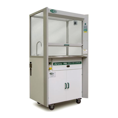
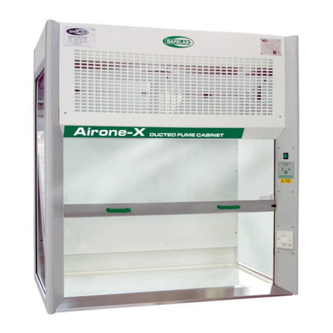
Safelab AIRONE 1000RS User manual

DOCUMENT NO: M21 ISSUE NO: 05 ISSUE DATE: 01/11/2015
1
INSTRUCTION MANUAL
Mobile AIRONE1000RS (110 Volt)
Filtration Fume Cupboard
SAFELAB SYSTEMS
Airone Building ● 8 Beaufighter Road ● Weston-Super-Mare ● BS24 8EE
WWW.SAFELAB.CO.UK

DOCUMENT NO: M21 ISSUE NO: 04 ISSUE DATE: 26/08/09
2
INDEX
Page Contents
3 Specification
3 The Sash & Two Speed Fan System
4 –5 Safelab Filters
5 Siting & Services
6 - 7 Instructions for Operation
7 What if? (Fault Finding)
8 Monitoring
Appendices
9 I. Fitting of the Main Carbon Filter.
10 II. Pre-filter Replacement
11 III. Monitoring the AIRONE 1000RS
12 IV. Instructions for Face Velocity Measurements.
13 AIRONE 1000RS Examination Record.
14 V. Instructions for Filter Saturation Testing.
15 VI. Main Block Wiring Diagram.
16 VII. Control System.
16 VIII. Calibration Procedures
17 IX. Siting Locations for AIRONE 1000RS.
18 X. Services.
18 XI. Spare Parts.
19 XII. E.C. Declaration of Conformity

DOCUMENT NO: M21 ISSUE NO: 04 ISSUE DATE: 26/08/09
3
SPECIFICATION
Construction: Aluminium extrusions and mild steel sheet, welded and
painted in epoxy powder coat, Light Grey RAL-7035 and
White RAL-9016. The fume enclosure is safety glass. The
front sash is safety glass. The top panel and baffle is acrylic.
Work Top: Polypropylene tray as standard.
Sliding Sash: The suspended/counterweighted front sash is in laminated
safety glass.
Dimensions:
External: 1000mm wide x 700mm deep x 1850mm high.
Internal (Fume Hood Enclosure): 950mm wide x 500mm deep x 865mm high.
Max. Sash Opening in Operation:840mm wide x 365mm high.
Max. Sash Opening for Loading: 840mm wide x 600mm high.
Weight (packed): 125kgs (including carbon filter).
Air-Flow Indication:
Low airflow indicated by red LED.
Fan: 2 x Centrifugal Fan
Noise level: 59 dBA
Supply: 110V 50/60Hz
THE SASH AND TWO SPEED FAN SYSTEM
The vertical sliding safety glass sash of the AIRONE 1000RS fume cupboard is
suspended and counterweighted providing added advantages over fixed-sash or
folding sash fume-hoods. E.g. the sliding safety glass sash can be closed and this
provides protection to operators in case of explosions.
The vertical sliding safety glass sash conforms to Paragraph 4.12 of the Building
Bulletin # 88 of the DofEE (Rev. of Design Note # 29) and BS:7258 requirements
in that the sash cannot fall if one of the suspending cable-cords are cut.
Moving the vertical sliding safety glass upwards and downwards causes the fan to
speed up or slow down to give a constant face velocity, this is controlled by a micro
switch.

DOCUMENT NO: M21 ISSUE NO: 04 ISSUE DATE: 26/08/09
4
SAFELAB FILTERS
Pre-filter: One piece cardboard framed blended synthetic fibre with
polypropylene spun-bonded scrim. (Safelab code: 101297 pack of 10
off)
The pre-filter is the white filter-layer which will filter out dust, smoke and mists.
It is accessed from the front of the cabinet. As the pre-filter becomes clogged from
dust, aerosols and particles accumulating on its surface the face velocity of the air
gradually decreases. Pre-filter replacement will be required more frequently than
that of the main filter. Replace pre-filters minimum of once every 3 months.
Main Filters ‘CMS’ Schools Impregnated/Activated Carbon Filter.
(Safelab code: 101094)
Weight: 22 kg - subject to humidity fluctuations. Or any one of
14 SAFELAB activated/impregnated carbon filters and/or HEPA
Filters (please refer to SAFELAB Filter-Guide)
Please refer to Adsorption Index - in Operational Safety Log-Book - consult with
Safelab Systems to obtain guidance in selection of appropriate filter and
monitoring procedures.
Safe Use
Following any fitting or replacement of the Main Filter the Work Station should be
run and the filter tested to ensure it has been installed correctly. Additionally, the
filter test for organic gases must be performed to verify correct filter seating.
Safelab Systems activated/impregnated carbon filters are of very high filtration
efficiency but, as human sensory perception is very acute and subjective (i.e. the
nose is very sensitive and its capability of sensing odours at various thresholds
varies from person to person) residual gases passing through the filter (such as
mercaptans or H2S) may sometimes be smelt, even though their levels of
concentration may be much below OEL and therefore may not be hazardous.
Calibrated GASTEC chemical detector tubes, or other approved/certified
appropriate chemical detectors/monitors should be employed when monitoring
concentration of compounds in gaseous phase in the laboratory, within the fume
enclosure or at the exit port of the workstations in the atmosphere. N.B.: If odours
of vapours or gases are causing distress, the operation should be finished and the
filter saturation monitored.
Users releasing hazardous vapours or gases must make their own assessment as
to whether it is safe to do so. Consult the Adsorption Index Chemical Listing in the
Operational Safety Log-Book when selecting the appropriate filter combination in
the AIRONE Fume Cupboard.

DOCUMENT NO: M21 ISSUE NO: 04 ISSUE DATE: 26/08/09
5
Chemical Hazard Analysis - Risk Assessment - under COSHH
Users must make their own assessment as to its efficiency of filters selected in
light of the variety of toxic vapours, gases and particulate contaminants released
within the fume enclosure and this filter selection must become part of routine
COSHH assessment. If in any doubt do not perform the operation. Consult Safelab
Systems to ensure correct filter selection was made and users have acquainted
themselves with filter monitoring procedures.
Siting
The intended locations for operation of the AIRONE 1000RS should be chosen so
that:
-The airflow into the sash opening is not hindered by walls, other fume
cupboards, cross draughts etc.
- Any wall opposite the front of the fume cupboard should be at least 2
meters away.
- The effects of doors and windows producing cross draughts are minimised.
-Please refer to BS:7258, Building Bulletin # 88 of the DfEE and the Safelab
Systems Operational Safety Log-Book for guidance on correct siting.
We recommend that the face velocity should be measured and variation checked
in all sites likely to be used.
NB: The fume cupboard should never be sited where it blocks an escape route.
Services
Electricity The Mobile AIRONE 1000RS requires a normal switched socket
outlet. The lead for the AIRONE 1000RS must be fitted with a 13
amp fuse. Extension cables should not be used.
Water/Gas Gas and water inlet and water outlet hoses can be passed through
the hole on the side of the base enclosure.
Note: The left and right front wheels should always remain locked when services
are connected.

DOCUMENT NO: M21 ISSUE NO: 04 ISSUE DATE: 26/08/09
6
INSTRUCTIONS FOR OPERATION
1. Use the AIRONE 1000RS sited in a place checked to be suitable.
2. Remember to lock the front wheels.
3. If intending to use Gas or Water services, make sure that the guidelines of
BS:7258 and Building Bulletin # 88 of the DfEE are met.
4. If you have Gas or Water on plumbed-in couplings, make sure that the
connectors are properly pushed home, the waste is secure and the hoses
do not cause a tripping hazard, and the tether is attached to the anchor
point on the wall or docking station.
5. Check through the window on the front of the cabinet that the filter label
with the code and name of the filter is clearly visible and that the filter is
fitted.
6. Remove everything from the cabinet that is not needed for your procedure.
7. Try to arrange apparatus and any emergency spillage kits beforehand.
8. Remember that the more compounds you handle and the more vapours you
release within the fume enclosure the shorter the filter life. Try to use
smaller amounts.
9. The spillage containment of the work top is 6 to 7 litres. The carbon filter
capacity varies from compound to compound and it is likely to be less than
3 litres. NB: Do not introduce chemical compounds and liquids in amounts
higher than the spillage tray and respective carbon filter capacities in order
to minimise risks of an overflow and/or filter saturation and filter-
breakthrough in case of accidental spillages.
10. Connect to power by inserting electric plug into socket and switch ‘On’ main
On/Off Switch. The Green Neon Light will come on to indicate the fans are
running.
11. Allow the fan to run with appropriate filter fitted for a few minutes before
introducing toxic chemical compounds into the fume enclosure to ensure
that the system has acquired its normal operational characteristics providing
the required/adequate face velocity.
12. Always wear eye protection while using the AIRONE Work Station.
13. If using Bunsen burners, always place them at least 20cm from the front,
sides or back baffle of the cabinet.
14. Always wait for all hazardous vapours or gases to clear before switching off
the cabinet. (Check that any bottles are stoppered and that no material has
been left on the necks or pooled around the bases.)

DOCUMENT NO: M21 ISSUE NO: 04 ISSUE DATE: 26/08/09
7
CLEANING
It is recommended that the AIRONE Fume Cupboard or Work Station is left
running during any cleaning procedure and that suitable protective clothing, face
mask, gloves and safety glasses are worn. Clean glass, acrylic, metalwork and
work surfaces with a mild detergent solution. After cleaning, wipe down all sur-
faces with a damp cloth.
WHAT IF ? .... AND FAULT FINDING.
1. What if I can smell the vapours or gases being used in the procedure?
Filters have a high efficiency but, because the nose is very sensitive, the
residual gases passing through the filter may sometimes be smelt, even
though their level is not hazardous. If the gases are causing distress, the
operation should be finished and the degree of filter saturation monitored.
2. What if I can smell the vapours or gases being used in the procedure,
but I have checked the filter performance and it is satisfactory ?
Check siting of the cabinet to ensure that nothing is being allowed to escape
out through the sash. Fume containment is easily impaired by draughts from
windows, doors or fan heaters and air vents.
3. What if there is a release that the filters of the Airone 1000RS cannot
contain?
If the initial chemical hazard analysis or risk assessment (under COSHH)
has been carried out correctly resulting in correct selection of appropriate
types of carbon filters followed by weekly air sampling and filter monitoring
checks this is unlikely to occur. In case it does happen, due to accidental
release of gas or vapour or an unexpected spillage, then leave the fan
running and evacuate the area. Subject to the hazard assessment and local
considerations, it may be that personnel with breathing apparatus would
have to return to open windows and ensure that all hazardous vapours or
gases had been dispersed.
Always keep a set of replacement carbon filters in the laboratory available
at short notice for such an event.
WARNING:
If a spill exceeds the capabilities of the Airone 1000RS, it is likely to exceed
the capabilities of carbon filtration face masks. This means that only an air
or oxygen cylinder based breathing apparatus could provide adequate
protection.

DOCUMENT NO: M21 ISSUE NO: 04 ISSUE DATE: 26/08/09
8
MONITORING
The minimum requirement to comply with COSHH Regulations is that the face
velocities and filter efficiencies must be monitored (at least once every 14 months)
and a written record kept of the results. Tables printed on back pages of the
Operational Safety Log-Book are suitable for keeping these records.
Safelab Systems recommend that a simple air sampling test be carried out once a
week at eye and mouth level and/or at the outflow port of the AIRONE Fume
Cupboard utilising an appropriate GASTEC Chemical Detector Tube (available
from Safelab Systems). Record result in the Operational Safety Log-Book.
It is also recommended that the pre-filter be replaced once every 3 months.
Safelab Systems offer Service Contracts for regular filter-monitoring and servicing
of all AIRONE Filtration Fume Cupboards. Please phone our Service Department
for details. Tel. No. 01934 421342
Refer to Appendices IV and V for face velocity and filter checking procedures.

DOCUMENT NO: M21 ISSUE NO: 04 ISSUE DATE: 26/08/09
9
Appendix I.
FITTING OR REPLACING THE MAIN CARBON FILTER
There should be no hazardous vapours or gases on the worktop and within the
fume enclosure during filter fitting or replacement.
During the filter replacement procedure, suitable protective clothing, face-
mask, gloves and safety glasses must be worn.
1. Disconnect the AIRONE cabinet from the mains supply.
2. Remove the filter-housing cover panel at the front to expose the main
carbon filter enclosure.
3. If replacing the main filter, remove the pre-filter from the top, and unscrew
the filter clamping knobs on each side of the filter.
4. Check that the new or replacement Safelab carbon filter is correctly
selected. Consult SAFELAB by phone, fax or e-mail.
5. Unpack the filter and place it gasket side upwards on a flat work surface.
(If replacing a filter, save the wrapping from the new filter and use it to
safely pack the old).
6. If replacing a filter, grip either side of the old main carbon filter and slide it
out of the housing, TAKE CARE ! the filter weighs about 22 kg and it may
require two people to remove it from the housing.
7. Slide the new filter into the place, between the guides in the main filter
chamber, gasket facing downwards and fully to the back of the unit.
When the filter is in place, tighten the two filter clamp knobs evenly and
firmly and stick the self-adhesive filter label to the front of the filter and write
the date of replacement on the label. Refit the pre-filter.
N.B. Good filter seating is essential for effective filtration.
8. Replace the front filter cover panel and securely fasten the screws.
10. Switch ‘On’ the cabinet.
11. Perform a filter seating test with Propan-2-ol (Isopropanol) to verify correct
seating of the newly fitted main filter.
12. Do not forget to update the Examination Record or fill in line on relevant
page in the Operational Safety Log-Book with a statement of filter fitting and
any results of the monitoring tests.
Written records of monitoring are a legal requirement under COSHH.

DOCUMENT NO: M21 ISSUE NO: 04 ISSUE DATE: 26/08/09
10
Appendix II.
PRE-FILTER REPLACEMENT
There should be no hazardous vapours or gases in the fume enclosure during
filter fitting or replacement.
During the filter replacement procedure, suitable protective clothing, face-
mask, gloves and safety glasses must be worn.
Access to the pre-filters is via the front of the work station.
1. Unscrew and remove the screws holding the filter access panel.
2. Withdraw the pre-filter from the top of the main filter. Seal the old pre-filter
into a polythene bag for disposal.
3. Should the pre-filter be particularly dusty, it can be gently sprayed with a
little water or glue from an aerosol can.
6. Carefully slide the new pre-filter in to place above the main filter with the tab
facing outwards.
7. Replace the filter access panel.

DOCUMENT NO: M21 ISSUE NO: 04 ISSUE DATE: 26/08/09
11
Appendix III.
MONITORING THE AIRONE 1000RS
This fume cupboard is a ‘portable appliance’, powered by mains electricity and it
complies with EN-BS-61010. The correct fuse must be fitted to the mains plug and
this and other exposed parts of the electrical system should be examined
frequently for obvious damage. There should be regular formal inspections
including earth bonding and insulation testing.
Information for users for Easy Do-It-Yourself filter-monitoring checks:
Equipment Needed
Airflow Meter: A rotating vane air flow meter with a vane diameter between 60 to
100mm., with the facility to average readings over a period of 10 seconds. Safelab
Systems supply a suitable airflow monitor (Safelab code SRVANE).
Unidirectional Hot-wire Anemometers are also available with the facility of
averaging readings.
Refer to Building Bulletin # 88 of the DfEE (rev. of Design Note #29)
GASTEC Volumetric Gas-Detection kit:
The GASTEC gas-detection kit consists of a disposable tube used with a
volumetric detector hand pump that draws a measured volume of air through the
tube. The length of colour change in the tube indicates the concentration of the
gas tested. SAFELAB SYSTEMS supply a suitable model:
GASTEC Volumetric Detector Pump (Safelab code SRV604).
N.B. Additionally packs of disposable tubes will be required.
Examples:
1 pack of 10 Sulphur Dioxide Tubes, 1 pack of 10 Trichloroethene. Tubes.
Refer to Operational Safety Log-Book and Chemical Listing for correct selection
from over 500 different GASTEC chemical detector tubes available for measuring
ppm concentration levels of over 800 compounds in gaseous phase.

DOCUMENT NO: M21 ISSUE NO: 04 ISSUE DATE: 26/08/09
12
Appendix IV
INSTRUCTIONS FOR FACE VELOCITY MEASUREMENTS
(Record results on record form - page 18 )
Procedure
Imagine the face of the fume cupboard divided
into nine cells.
Stand as far as practicable from the fume
cupboard with the sensing head in the plane of
the sash and take airflow readings at
approximately the centres of each of the nine
cells.
Record for each cell the approximate average reading over a period of at least ten
seconds, applying any corrections from the air flow meter calibration chart.
Look at the table and repeat any reading which seems to be very different from the
general pattern. Record the average of this and the previous reading.
Calculation
Minimum face velocity -
Record which of a, b,c,d,e,f,g,h,i, is the smallest, i.e.: the minimum face velocity.
If it is below 0.3 m/s then containment factors are impaired and the cause will have
to be found and remedied.
Variation
Check for variation as follows :
Add together the values a,b,c,d,e,f,g,h,i and divide by 9 to get the average.
Find the biggest and smallest of a,b,c,d,e,f,g,h,i.
The upper percentage variation is the biggest minus the average, divided by
the average and multiplied by 100.
The lower percentage variation is the average minus the smallest, divided by the
average and multiplied by 100. Each of these should be below 30%, if not, then
the Airone 1000RS has been parked in an unsuitable site and will have to be
moved. (See Appendix IX for siting guidance.)

DOCUMENT NO: M21 ISSUE NO: 04 ISSUE DATE: 26/08/09
13
AIRONE 1000RS EXAMINATION RECORD
Site:..............................................................................
.............................................................
Location of Airone 1000RS:
.....................................................................................
..........……………………………………………
Air flow meter: ..................................................
used
Date
Of
Check
Readings in each of the cells as
above.
Average
( m/s )
Drop
>
10%
from
Do
filters
PASS
Is
Fume
flow
Any deterioration or
damage observed.
Fail if face velocity
Initials
of
Tester
a
b
c
d
e
f
g
h
i
Before
Check
Inward
< 0 . 3 m / s
If a drop of 10% is found then the cause of the problem should be cleared. (Check Prefilters.)
If the minimum face velocity is below 0.3 m / s then airflow in the fume cupboard is inadequate.

DOCUMENT NO: M21 ISSUE NO: 04 ISSUE DATE: 26/08/09
14
Appendix V.
INSTRUCTIONS FOR FILTER SATURATION TESTING.
Regular filter checks and monitoring (once a week is recommended) to test quality
of the air breathed in by operators and filtration efficiency. Filter challenge tests
can be carried out during routine Service and Maintenance procedures once every
6 months as described in the Operational Safety Log Book.
The recommended procedure for testing the efficiency of the system requires a
GASTEC Volumetric Detector Pump and Gastec Chemical Detector Tubes. Test
the quality of air by sampling at eye and mouth level at regular intervals once a
week with Gastec tubes calibrated for the particular compound in concentrations
below its respective OEL (Occupational Exposure Limit) MEL (Maximum Exposure
Limit) or OES (Occupational Exposure Standard (or MAK in Germany and/or TLV
in the USA).
Please refer to the Chemical Listing, Adsorption Index and Gastec Detection Guide
published in our Operational Safety Log-Book.

DOCUMENT NO: M21 ISSUE NO: 04 ISSUE DATE: 26/08/09
15
Appendix VI.
MAIN BLOCK WIRING DIAGRAM

DOCUMENT NO: M21 ISSUE NO: 04 ISSUE DATE: 26/08/09
16
Appendix VII.
CONTROL SYSTEM
The Low Air Flow Alarm indicator does not replace confirmatory checks and
routine frontal face velocity testing requirements with a calibrated anemometer or
airflow meter.
These should be carried out regularly and the results recorded in the appropriate
section this book, or the Operational Safety Log-Book as required under COSHH
Regulations.
ON/OFF switch
Low airflow warning LED
Appendix VIII.
CALIBRATION PROCEDURE
1) Remove control panel to access speed control PCB and pressure switch.
2) Switch on unit, and position the sash so that the top edge is just below micro
switch (top RH side behind upper fascia panel).
3) Using a hand held anemometer, adjust RV1 on the speed control PCB until an
average airflow of 0.4m/s is achieved at the sash opening.
4) Raise the sash to its highest position (365mm), and rotate RV2 on the speed
control board fully clockwise (fans at full power).
5) Raise sash to just trigger micro switch. Block approx. 90% of the rear air duct at
the back of the work tray..
6) Adjust the screw on the pressure switch so that the red LED warning light just
starts to flicker.
7) Switch off the unit and replace the control panel.

DOCUMENT NO: M21 ISSUE NO: 04 ISSUE DATE: 26/08/09
17
Appendix IX.
SITING LOCATIONS FOR AIRONE 1000RS.

DOCUMENT NO: M21 ISSUE NO: 04 ISSUE DATE: 26/08/09
18
Appendix X
SERVICES
Couplings for Services.
When supplied with services, provision has to be made to connect the Airone
1000RS to gas, water or waste plumbing.
Water and Gas.
The quick connect hose couplings used on the Airone 1000RS are self sealing -
both at the wall coupling ( male ) and at the hose coupling ( female ).
Plumbing fittings that will have to be provided on the building pipework are :-
For the water coupling - one 1/4” BSP male threaded outlet.
For the gas coupling - one 1/8” BSP male threaded outlet.
Each of these should be have a suitable stopcock and local regulations should be
consulted with respect to requirements for air-breaks and maximum stub pipe
lengths.
Waste.
The waste outlet from the Airone 1000RS is a flexible non-kink PVC hose.
The end of this hose is terminated with a modified plug and locking nut
arrangement suitable for insertion directly into a 38mm VulcatheneTM mechanical
waste fittings.
When the Airone 1000RS is not connected to the waste , the wall fitting should be
blanked off using a type W24 blanking plug and W231 38mm nut.
Appendix XI.
SPARE-PARTS
101297 - Pack of Pre-filters
101094 - Main CMS Filter (For other filters see brochure and price list)
050201 - Mains Lead
060250 - Fan (x2)
170600 - Water Hose (To supply)
170603 - Water Hose (Valve to outlet)
170601 - Gas Hose Assembly (To supply)
170604 - Gas Hose Assembly (Valve to outlet)
170500 - Waste Hose
050245 - On/Off Switch
050643 - Red LED
040300 - Duel Speed Control PCB Assembly

Table of contents
Other Safelab Laboratory Equipment manuals
Popular Laboratory Equipment manuals by other brands

VWR
VWR avantor Premium Balance Analytic PBA operating instructions

MRC
MRC Nilsen quick start guide

logos biosystems
logos biosystems Luna II manual

AMX
AMX PS-POE-AF installation guide

Socket
Socket DURASCAN D840 Series Programming guide

Endress+Hauser
Endress+Hauser Liquistation CSF48 operating instructions