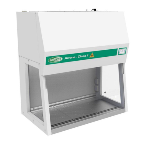
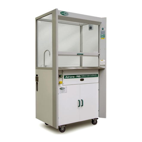
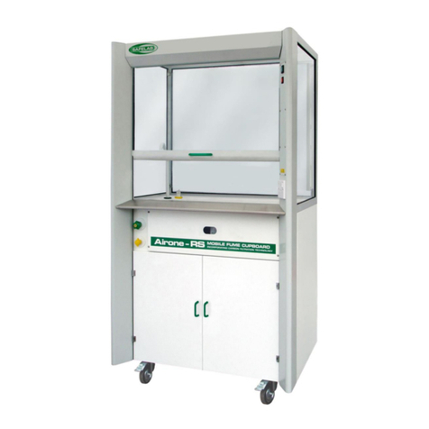
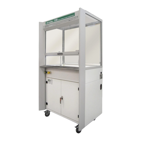
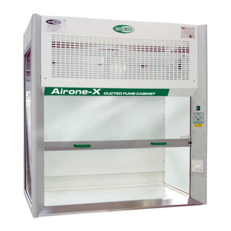
Safelab XP4 User manual

2 DOCUMENT N°: M47 ISSUE N°: 05 ISSUE DATE: 08/11/2021
CONTENTS
SECTION 1
1.1. FOREWORD ......................................................................................................................................................... 4
1.2. WARNING NOTICES ............................................................................................................................................. 5
1.3. PRECAUTIONS...................................................................................................................................................... 5
1.4. GENERAL OPERATING CONDITIONS .................................................................................................................... 5
1.5. ENVIRONMENTAL CONDITIONS. ......................................................................................................................... 5
1.6. ELECTRICAL SAFETY ............................................................................................................................................. 6
1.7. SAFETY NOTICE.................................................................................................................................................... 6
1.8. ENVIRONMENTAL PROTECTION.......................................................................................................................... 7
1.9. INTRODUCTION ................................................................................................................................................... 7
1.10. PRINCIPLES OF OPERATION................................................................................................................................. 8
1.11. IMPROPER USE. ................................................................................................................................................... 9
1.12. GUIDELINES FOR SAFE USE.................................................................................................................................. 9
SECTION 2
2.1. SPECIFICATION .................................................................................................................................................. 10
2.2. SPECIFICATION DIAGRAM ................................................................................................................................. 11
SECTION 3
3.1. OPTIONAL FEATURES......................................................................................................................................... 12
3.2. INSTALLATION ................................................................................................................................................... 12
3.3. ASSEMBLY INSTRUCTIONS................................................................................................................................. 12
3.4. SUPPORT FRAME ASSEMBLY ............................................................................................................................. 13
3.5. LOCATION OF FUME CUPBOARD....................................................................................................................... 14
3.6. CONNECTIONS (Gas and Water are optional) ................................................................................................... 15
SECTION 4
4.1. OPERATING INSTRUCTIONS............................................................................................................................... 16
4.2. CONTROL PANEL FEATURES .............................................................................................................................. 17
4.3. DISPLAY FEATURES ............................................................................................................................................ 18
4.4. CONTROL PANEL OPERATION ........................................................................................................................... 18
4.5. AIRFLOW INDICATOR ........................................................................................................................................ 19
4.6. FAN FAIL ALARM................................................................................................................................................ 19
4.7. HIGH SASH ALARM ............................................................................................................................................ 20
4.8. VAV DAMPER OVERRIDE ................................................................................................................................... 20

DOCUMENT N°: M47 ISSUE N°: 05 ISSUE DATE: 08/11/2021 3
SECTION 5
5.1. LIGHT SWITCH ................................................................................................................................................... 21
5.2. ELECTRICAL SOCKETS (Optional) ....................................................................................................................... 21
5.3. SERVICES (Optional) .......................................................................................................................................... 21
5.4. PIR SENSOR (Optional) ...................................................................................................................................... 21
SECTION 6
6.1. WIRING DIAGRAMS ........................................................................................................................................... 22
6.2. MAINTENANCE AND PERFORMANCE MONITORING:........................................................................................ 24
6.3. SPILLAGES.......................................................................................................................................................... 25
6.4. SPARES PARTS ................................................................................................................................................... 25
6.5. NOTES (left blank for notes).............................................................................................................................. 26
CERTIFICATE OF CONFORMITY ......................................................................................................................... 27

4 DOCUMENT N°: M47 ISSUE N°: 05 ISSUE DATE: 08/11/2021
1. SECTION 1
1.1. FOREWORD
This manual has been prepared to give guidance in the use of your Airone XP4 Ducted Fume
Cupboard.
It is recommended that service and maintenance operations should only be undertaken by SAFELAB
Service Engineers or their authorised agents.
Details of Service Contracts/Programmes, along with further information on our range products, are
available on request from:
Airone Building
8 Beaufighter Road
Weston-Super-Mare
BS24 8EE
Telephone - +44 (0)1934 421340
E-mail - [email protected]
Website: - http://www.safelab.co.uk
NOTE:
This Fume Cupboard will require an inspection and test under COSHH regulation 9 by a suitably
qualified engineer.
We recommend that this Fume Cupboard is examined and tested annually, in order to be compliant
with regulation 9.2.a at all times.
COSHH Regulation 9 Maintenance, Examination and Testing of Control Measures
(2) Where engineering controls are provided to meet the requirements of regulation 7, the
employer shall ensure that thorough examination and testing of those controls is carried out
(a) in the case of local exhaust ventilation plant, at least once every 14 months.

DOCUMENT N°: M47 ISSUE N°: 05 ISSUE DATE: 08/11/2021 5
1.2. WARNING NOTICES
Within this User Manual WARNINGS are used to highlight information or instructions that must be
followed in order to avoid personal injury to yourself or other people in the vicinity, eg. switch off
the mains voltage before any maintenance.
WARNINGS appear as below:
WARNING
Switch off the mains voltage and remove the mains cord before
maintenance.
1.3. PRECAUTIONS
The following precautions must be observed when using the Fume Cupboard:
•Be sure that the voltage of the Fume Cupboard corresponds to the voltage available
where it is to be installed
•Never remove the side or front covers of the Fume Cupboard without first isolating the
equipment and disconnecting the mains cord
1.4. GENERAL OPERATING CONDITIONS
The Fume Cupboard has been designed and tested in accordance with the safety requirements of
the International Electrotechnical Commission (IEC). The Fume Cupboard conforms to IEC61010-1
(Safety Requirements for electrical equipment for measurement, control and laboratory use) as it
applies to IEC Class 1 (earthed) appliances, and therefore meets the requirements of Low Voltage
Directive 2014/35/EU.
If possible, avoid any adjustment, maintenance or repair to the equipment whilst covers are open
or it is in operation. However, if any adjustment, maintenance or repair is necessary while the
covers are open, this must be done by a competant person who is aware of the hazards involved.
1.5. ENVIRONMENTAL CONDITIONS.
This Fume Cupboard should only be used under the following conditions:
•Indoor-use only
•Must be connected to a suitable extract system
•Unit to be sited away from the influence of draughts
•Electrical supply fluctuation not exceeding +10% of the nominal voltage
•In ambient temperatures between 5°C and 40°C
•With relative humidity below 80% for temperatures up to 31°C, decreasing linearly to 50%
relative humidity at 40°C
WARNING
The protection provided by the equipment may be impaired if the
environmental conditions do not lie within these parameters.

6 DOCUMENT N°: M47 ISSUE N°: 05 ISSUE DATE: 08/11/2021
1.6. ELECTRICAL SAFETY
The Fume Cupboard is designed to protect the user from potential electrical hazards. This section
describes some recommended electrical safety practices.
WARNING
Lethal voltages are present at certain points within the equipment.
When the equipment is connected to mains power, removing the
equipment covers is likely to expose live parts.
Even when the power switch is off, high voltages can still be present –
capacitors within the equipment may still be charged even if the
equipment has been disconnected from all live voltage sources.
The Fume Cupboard and associated equipment must be correctly connected to a suitable electrical
supply. The supply must have a correctly installed protective conductor (earth or ground) and must
be installed and checked by a qualified electrician before initial power up.
WARNING
Any interruption of the protective conductor inside or outside of the
Fume Cupboard, or disconnection of the protective conductor terminal,
is likely to make the equipment dangerous.
Intentional interruption of the protective conductor is prohibited.
WARNING
If the mains power cord has to be replaced, ensure that the
replacement cord is appropriately rated and approved for the intended
use.
WARNING
To prevent potential personal injury or damage to the equipment,
switch OFF all components in the system and disconnect them from the
mains power supply before altering or making any new electrical
connections.
1.7. SAFETY NOTICE.
This Fume Cupboard must be used in compliance with these instructions and any repairs or
maintenance carried out by a competent person.
It is important that you read the instruction manual before first use and keep it in a safe place for
future reference.
DISPOSAL
Dispose of packaging in an environmentally-friendly manner.
This appliance is labelled in accordance with European directive 2012/19/EU
concerning used waste electrical and electronic equipment (WEEE).
This symbol means the disposal of this equipment must be handled separately
from general urban waste.
Appropriate disposal of this equipment will help to prevent potential negative
effect on the environment and to promote re-use or recycling of materials.

DOCUMENT N°: M47 ISSUE N°: 05 ISSUE DATE: 08/11/2021 7
1.8. ENVIRONMENTAL PROTECTION
Chemical fumes that are extracted through the Fume Cupboard and duct system are exhausted to
atmosphere, where they are diluted many times over and have a negligible effect on human health.
However, where large volumes of chemicals are being used, additional considerations need to be
made for preventing the emission of noxious or offensive substances into the atmosphere, which is
a legal requirement under the Environmental Protection Act 1990.
1.9. INTRODUCTION
A Fume Cupboard is a local ventilation device that is designed to conform to BSEN 14175 to limit
exposure to hazardous chemical fumes, vapours, gases, dusts, mists and aerosols. This type of
laboratory equipment provides a physical barrier between reactions within the Fume Cupboard and
the operator and laboratory, by offering a measure of protection against inhalation exposure and
chemical spills.
A Fume Cupboard does this by maintaining a negative pressure within the interior of the cabinet to
prevent any contaminant from escaping, whilst drawing air in through the sash opening at a constant
rate. A face velocity (the speed at which air is drawn into the cabinet) is of importance to the safe
and effective operation of a Fume Cupboard. Your XP4 unit should be set to run at 0.5m/sec, with
the sash at the maximum safe working height (normally 500mm).

8 DOCUMENT N°: M47 ISSUE N°: 05 ISSUE DATE: 08/11/2021
1.10. PRINCIPLES OF OPERATION
Air is drawn into the cupboard at the Front Working Aperture (A) below the sliding sash at a velocity
high enough to ensure containment of any fumes, odours or contaminants given off by the processes
carried out within the cupboard.
The fumes from within the cupboard are drawn either upwards as in the case of lighter-than-air
(vapour density < 1) fumes (B) to the Extract Slot (D), or drawn across the work surface to the
Secondary Extract Slot (E) created by the back baffle, as in the case of heavier-than-air (vapour
density > 1) fumes/particulates (C).
The combination of Extract Slots (D) and (E) ensure that all fumes/particulates are carried by the
moving body of air to the Extract Slot and Duct Transition Adaptor (F) and on into the Extract Duct
System (G).
On a constant air volume unit (CAV) as the sash is lowered air will pass through the bypass grill on
the Front Cover (H).
CAV UNIT VAV UNIT

DOCUMENT N°: M47 ISSUE N°: 05 ISSUE DATE: 08/11/2021 9
1.11. IMPROPER USE.
This Fume Cupboard must be used and operated only in accordance with the user manual, any
alterations or disabling of safety features is a violation of the intended use and as a result could cause
a danger to person or property.
WARNING
To prevent potential personal injury and damage to the equipment, the
Fume Cupboard must be operated in accordance with the user manual.
1.12. GUIDELINES FOR SAFE USE.
•Only trained personnel should use the Fume Cupboard
•Always follow your standard operating procedure (SOP)
•Only use the Fume Cupboard if it has been serviced within the last fourteen months
•Ensure the extract is working and the display is indicating the unit is safe before commencing
work
•When using the Fume Cupboard, never put you head inside the unit. Remember the barrier
between clean and contaminated air is the plane of the sash
•Always use the appropriate personal protective equipment (PPE)
•Open windows, doors, fans of air conditioning units and movement of people will all cause
airflow disturbance, which can reduce the effectiveness of the Fume Cupboard’s containment
•Always work with the sash in the lowest practical position to maximise performance
•Keep the sash closed when not in use
•Keep hazardous chemicals and any reactions at least 15cm behind the plane of the sash
•Report any Fume Cupboard faults immediately
•Close the sash in the event of an electrical power failure
•Do not use the Fume Cupboard as a store, even temporarily, for chemical solvents
•Do not use the Fume Cupboard as a waste disposal mechanism
•Do not remove any panels or covers
Definition: The Airone XP4 Ducted Fume Cupboard has been designed and tested to meet the
containment characteristics requirements of BS EN14175-1:2003 (barring outside
influences i.e. building columns and poor siting).
Application: Whenever the operator and/or the environment need to be protected from
gaseous or particulate contaminants.

10 DOCUMENT N°: M47 ISSUE N°: 05 ISSUE DATE: 08/11/2021
2. SECTION 2
2.1. SPECIFICATION
Model
1.2
1.5
1.8
2.0
Electrical supply:
230V / 50Hz (As standard the unit is fitted with a standard 13A plug top.)
Installation/overvoltage
category:
ll
Pollution degree:
2
Nominal power
cabinet:
70W*
60W*
Nominal power Aux
Sockets
2300W**
2300W**
Weight
200kg
230kg
260kg
280kg
Inflow
0.5m/s at a maximum working aperture of 500mm
Lights
LED >690LUX at the work surface
LED >850LUX at the work surface
Duct connection size
250mm
315mm
315mm
*Units without electrical sockets
**Units with electrical sockets option
Construction: Main structure, aerofoils and cover panels: Aluminium extrusions or mild steel,
painted in epoxy powder coat
Internal lining, baffles and top panel: High pressure compact laminate (HPL), or to
customer specification
Work tray: Grey cast epoxy resin as standard, although ceramic work trays are available as an
option
Sash: The vertical sliding sash is toughened safety glass with an epoxy powder-coated
extruded aluminium handle. As standard it is manually operated and suspended
by a counterweight
Maximum working height = 500mm and with Maximum maintenance = 840mm
Control Panel: Digital control system located on the right-hand aerofoil
Light Switch: For the integral LED light fitting, this is located on the left-hand aerofoil
Services: Optional and to customer specification. (also see connections page 15)
Dimensions including base stand (in millimetres) for standard units:
Unit
Model
External (mm)
Internal (mm)
Width
Depth
Height
Width
Depth
H. front
H. rear
1200
1200
900
2400*
900
615
1200
975
1500
1500
900
2400*
1200
615
1200
975
1800
1800
900
2400*
1500
615
1200
975
2000
2000
900
2400*
1700
615
1200
975
* 2690mm with sash fully open in maintenance height.

DOCUMENT N°: M47 ISSUE N°: 05 ISSUE DATE: 08/11/2021 11
2.2. SPECIFICATION DIAGRAM
1: Hinged top panel
7: Digital control panel
2: Light switch
8: Sliding sash
3: Sash stop
9: Services (optional)
4: Double socket outlet (optional)
10: Rear baffle
5: Support stand
11: Sill
6: Airflow sensor

12 DOCUMENT N°: M47 ISSUE N°: 05 ISSUE DATE: 08/11/2021
3. SECTION 3
3.1. OPTIONAL FEATURES
Your unit may be fitted with the following optional features:
•Electrical socket outlets: Maximum of 2 x DSSO can be mounted on each aerofoil
•Services: Liquid & Gas service
•PIR sensor: Unit will alarm if the sash is left open, whilst unattended
•Consumer unit: Where more amperage is required for electrical sockets
•Auto-sash: Motor driven sash, open and closes automatically
3.2. INSTALLATION
The XP4 is designed to sit flush to the ceiling and doesn’t have a top panel. If the ceiling height is
above 2.4m, infill panels will be required to prevent access to the electrical compartment on units
with the auto-sash option.
WARNING
If the ceiling is above 2.4m, infill panels will be required to prevent
access to electrics on top of the unit.
3.3. ASSEMBLY INSTRUCTIONS
Only the support frame needs to be assembled, although this should be assembled and sited by
specialists using the correct handling equipment. Please contact Safelab Systems for assistance in this
matter.
Space for free air circulation must be provided around the Fume Cupboard (see page 14 for a guide
to siting the cupboard).
Your Fume Cupboard was supplied with the follow documentation:
-Operational Manual - Quality Pass
-Service and Maintenance Letter - Conformity certificates
-Safety Log Book - Warranty form

DOCUMENT N°: M47 ISSUE N°: 05 ISSUE DATE: 08/11/2021 13
3.4. SUPPORT FRAME ASSEMBLY
The support frame/stand is an important structural part of the Fume Cupboard, and once sited with
the unit in place the lower rear brace panel must not be removed for any reason.
The pallet design is such that the two end sections can be removed. The unit can then be lifted on
the pallet and the fully constructed stand slid in under the Fume Cupboard.
The stand should then be bolted onto the Fume Cupboard frame using the 4 x 100mm M6 bolts.
Once this has been completed, the Fume Cupboard and stand can be lowered onto the floor.
WARNING
Unit must be secured to the stand.
WARNING
Lower rear brace panel must not be removed with the Fume Cupboard
on the stand.

14 DOCUMENT N°: M47 ISSUE N°: 05 ISSUE DATE: 08/11/2021
3.5. LOCATION OF FUME CUPBOARD
Fume Cupboard location should be chosen to minimise any undue airflow disturbances, which will
reduce the risk of contaminants leaving the Fume Cupboard and the chances of anomalous results
when carrying out the annual inspection test.
A general guide to suitable distances from common airflow disturbances is shown below and if any
Fume Cupboards are found to be exposed to these conditions it should be noted in the unit’s Log
Book.
Further information can be found in BSEN 14175-5:2006 (4.2)
GUIDE TO POSITIONING LOCATIONS FOR THE AIRONE XP FUME CUPBOARD

DOCUMENT N°: M47 ISSUE N°: 05 ISSUE DATE: 08/11/2021 15
3.6. CONNECTIONS (Gas and Water are optional)
Ducting:
Once sited, the Fume Cupboard needs to be connected to the duct extract
system
Unit duct spigot size:
- 1.2 wide unit = Ø250mm
- 1.5, 1.8 & 2.0 wide units = Ø315mm
Control system:
The unit control system needs to be connected to the extract fan control
system (where applicable)
Water services:
As standard 10mm Nylon hose supplied with push fit fitting, terminating with
¼” male thread, or to customers order specification
Waste:
Supplied with 38mm Vulcathene anti-siphon bottle trap
Natural Gas:
Flexible gas hose terminated with ¼” female thread or to customers order
specification (must be connected by a qualified gas safe installer)
Gases non-burning:
As standard 10mm Nylon hose supplied with push fit fitting, terminating with
¼” male thread, or to customers order specification
Once all connections are complete, the Fume Cupboard is now ready for commissioning.

16 DOCUMENT N°: M47 ISSUE N°: 05 ISSUE DATE: 08/11/2021
4. SECTION 4
4.1. OPERATING INSTRUCTIONS
(ENSURE THE UNIT IS PLUGGED IN TO THE MAINS ELECTRICAL SUPPLY)
A Fume Cupboard is only a partial enclosure and cannot provide absolute protection against
inhalation of substances used within. In addition, the degree of protection given to the user is
dependent on other factors, such as the system of work and the nature of the operations to be
performed. For guidance on the risk for particular applications, the purchaser should refer to both
the long and short-term exposure limits for airborne chemicals, which are published by the Health &
Safety Executive. These limits provide guidance on the levels (in terms of concentration and time) to
which exposures to airborne toxic substances should be controlled.
When working with hazardous substances, always consult Safe Systems of Work, which should be
provided by your employer.
Position apparatus and materials in the Fume Cupboard so as to minimise disturbance to the airflow
at the working aperture and so that it is possible to quickly close the sash without any risk of
disturbing the apparatus within.
Always use appropriate PPE (personal protection equipment) when using a Fume Cupboard.
Always close the sash when leaving the Fume Cupboard unattended.
After use, follow the correct procedures for disposal of any residues, and leave the Fume Cupboard
in a safe state for further use by others.

DOCUMENT N°: M47 ISSUE N°: 05 ISSUE DATE: 08/11/2021 17
4.2. CONTROL PANEL FEATURES
VAV CONTROLLER
(Variable Air Velocity)
CAV CONTROLLER
(Constant Air Velocity)

18 DOCUMENT N°: M47 ISSUE N°: 05 ISSUE DATE: 08/11/2021
4.3. DISPLAY FEATURES
VAV DISPLAY (Variable air velocity)
CAV DISPLAY (constant air velocity)
4.4. CONTROL PANEL OPERATION
1. Where practical, place any apparatus required inside the Fume Cupboard before commencing
process. The design of the cupboard is for the sash opening to be at a maximum normal working
height of 500mm from the worktop. To increase safety it is good practice to keep the sash in the
closed position as much as possible.
2. With the sash at the maximum working height (normally 500mm) switch on the extract system
using the Fan START/STOP Button I (see page 17) from the control panel.
When the FAN START Button is pressed, the fan will switch on and the control screen will display
“START UP”as well as counting down from 9 seconds. Note the alarm is muted during this period.
After this period if the fan is not fully up to speed, the display will alternate between the air
velocity reading and “AIR FAIL”message. The alarm will sound and the “ALARM”red LED will
flash for a very limited time until the fan is up to speed.
Once the fan is up to running speed, 0.5m/sec, the “AIR SAFE” green LED will illuminate. The
Fume Cupboard is now ready to use.
Fan off
No airflow
Start Fan
Button I
Fan not up to speed
Airflow reading in red
or amber depending
on velocity
Fan up to speed
Reading turns white
and the “AIR SAFE”
LED shows green

DOCUMENT N°: M47 ISSUE N°: 05 ISSUE DATE: 08/11/2021 19
3. To stop the fan after use, press Button I again and close the sash (remember to empty the
cabinet of all chemicals prior to switching the fan off).
When the button is pressed, the screen will go into sleep mode and display “OFF”. The
“ALARM” LED will flash red and the alarm sound will be muted automatically.
4.5. AIRFLOW INDICATOR
(CAV Screen shown)
Low airflow:
•Velocity reading shown in red
•Display alternates between airflow reading and “AIR FAIL”
message
•Alarm red LED flashes
•Alarm sounds
Acceptable airflow:
•Velocity reading shown in yellow
•Caution yellow LED flashes
Good airflow:
•Velocity reading shown in white
•Safe green LED on
4.6. FAN FAIL ALARM
A failure of the fume extract system will be indicated by the display indicating “AIR FAIL”, a red LED
flashing and an audible tone being heard. The air velocity display will also turn red. At this point the
sash should be closed to maximise containment. Pressing the “ENTER” button will mute the alarm.
Display alternates between “AIR FAIL” and the velocity reading
Alarm sounds & red LED flashes
Display in sleep mode

20 DOCUMENT N°: M47 ISSUE N°: 05 ISSUE DATE: 08/11/2021
4.7. HIGH SASH ALARM
Should you require the sash to be raised above the maximum working height (i.e. for setting up
equipment) the sash stop plunger (page 11 item 4) needs to be manually pulled out to allow the sash
to move.
If the extract is on and the Fume Cupboard is operated with the sash above the maximum working
height, the amber caution LED will illuminate and the alarm will sound. The display will alternate
between “SASH HIGH” and the face velocity to warn that containment levels and airflow velocities
are compromised.
Pressing the “ENTER” Button can mute the alarm. When muted the amber LED will flash and the
alarm will reactivate after a time of approximately 5 minutes if the sash is not returned to normal
operating height.
When the sash is above the maximum working height and the airflow velocity drops below
0.39m/sec, the “AIR FAIL” alarm will trigger and both the amber & red LEDs will flash. Again, the
alarm can be muted for a short period.
The display will alternate between face velocity, “SASH HIGH” face velocity and “AIR FAIL”.
Sash above maximum
working height
A message is displayed
Sash above maximum
working height
Amber LED illuminates
Sash above maximum
working height with
low airflow
Messages will
alternate
Sash above maximum
working height with
low airflow
Both the amber & red
LEDs will illuminate
4.8. VAV DAMPER OVERRIDE
On a VAV Fume Cupboard it is possible to override the extract damper by using Button III.
Pressing Button III once will switch from VAV Run to VAV Max, this will open the damper fully to
increase the airflow velocity through the Fume Cupboard for a set time.
Pressing Button III again will switch from VAV Max to VAV Min, this will close the damper and
decrease the airflow velocity through the Fume Cupboard
VAV Run
Default setting: The damper
will adjust automatically to
maintain the airflow velocity
VAV Max
Purge: Damper fully open for
maximum airflow extract in
the event of a spillage/
emergency
VAV Min
Reduced velocity: Damper
closes to reduce airflow -
sometime required for powder
work
Table of contents
Other Safelab Laboratory Equipment manuals
Popular Laboratory Equipment manuals by other brands

Ken A Vision
Ken A Vision Video Flex 5400 installation manual

IKA
IKA lab dancer 3365000 operating instructions

Endress+Hauser
Endress+Hauser Analytik Jena Biometra TSC ThermoShaker manual

PI
PI H-824 user manual

Bruker
Bruker minispec TC3 user manual

Stereotaxis
Stereotaxis Niobe PM3.1 Installation Verification and Testing