SAFERA PCU6.3-F User manual

21023_02-B
Installation manual
Safera Siro R stove guard
PCU6.3-F PCU6.3-PPCU6.1-F PCU6.1-SPCU6.1-P

2
Contents
1. Preparations
2. Installation
3. Troubleshooting
4. Optional: Installing the Water Leak-
age Sensor
Follow these instructions carefully and
pay particular attention to the instruc-
tions marked in the following way:
ѥWARNING
Follow instructions marked with a
warning accurately to prevent injury
to persons and damage to property.
⚐ATTENTION
Follow instructions marked with a
note carefully to prevent damage to
property.
ѧHINT
Hints give you useful advice on using
the appliance.
Warnings
ѥWARNING
Read user and installation manual be-
fore using or installing the appliance.
Install and check the application ac-
cording to the instructions. Safera is
not liable for any damage or expens-
es caused by inappropriate installa-
tion.
Check that the Stove Guard is com-
patible with the cooker (see section
1.1).
If the connection cord is damaged, it
must be replaced by the service per-
sonnel of the manufacturer or their
representative to avoid hazards.
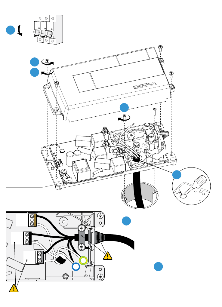
All electrical connections must be
carried out by a qualiied electrician.
⚐ATTENTION
If the appliance was stored in a cold
space, it must be allowed to warm
up to room temperature before con-
necting it to mains power.

3
1. Preparations
Check the product and the contents of
the package before installation:
• Sensor unit with mounting bracket Ⓐ
• Power Supply Ⓓ
• Power Control Unit Ⓒ
• User and Installation Guides
ѥWARNING
Please contact your vendor if you no-
tice anything unusual about the ap-
pliance.
1.1 Compatibility
Safera Stove Guard is compatible with
most electrical cookers, hobs and ovens
meant for household use:
• Traditional cast-iron cookers and
hobs
• Ceramic cookers and hobs
• Induction cookers and hobs
• Cookers and hobs equipped with
a timer, afterheat indicator, child
proof lock or integrated switch-o
system
Safera Siro R is compatible with cook-
ers no wider than 90 cm, see chapter 2.
Installation step 1/6.
1.2 Control Panel
❶ Child proof lock button
❷ OK button
❸ Indicator light for child proof lock
❹ Indicator light for normal activity
❺ Warning light for cooktop hazard
❻ Warning light for water leakage
❼ Adjustment mode button
❽ Indicator light panels
❾ Sensor
8
91
3
72
4
5 6
Ⓐ
Ⓒ
Ⓓ

4
Install the Cental Unit Ⓐon the wall above the cooktop and follow these dimensions:
Min 8 mm Min 5 mm
Cooker
width
Installation
Height
Max. 60 cm 45 - 75 cm
60 - 90 cm 60 - 75 cm
Width
Align the Sensor unit
±15 mm with the centre
of the cooktop.
Depth
Align the sensor of
Sensor unit (white
lens) ±100 mm with the
centre of the cooktop.
2. Installation Mount the Sensor unit Ⓐ- Step 1/6

5
⚐ATTENTION
The Sensor unit Ⓐis plugged into
the wall socket with its own power
supply Ⓓ.
200 mm
12
”Click”
3
”Click”
4
5
Mount the Sensor unit Ⓐ

6
Install the Power Control Unit according to the following instructions.
2. Installation - Step 2/6 Mount the Power Control Unit Ⓒ
PCU6.3P
Perilex-connectors.
See pages 10-11.
PCU6.1F
Fixed 1-phase connection.
See pages 12-13.
PCU6.3F
Fixed 3-phase connection.
See pages 8-9.

7
Mount the Power Control Unit Ⓒ
PCU6.1P
1-phase, 3-pin plug OUT.
See pages 14-15.
PCU6.1S
Schuko-connectors.
See pages 16-17.

8
ѥWARNING
Make sure that there is no power sup-
ply to the cooker and the oven by re-
moving their fuses. Also ensure that
the cooker is switched o.
OUT-wires are always energized when
the power control unit is connected
to the mains power. If a wire is loose,
it must be properly covered.
Do not install the power control onit
to excessive heat: See operational
ambient temperature on the power
control unit Ⓒ.
⚐ATTENTION
Install the power control unit Ⓒ so
that it is not exposed to moisture.
Check that all cables can move freely.
If you are replacing a cooker, press
the adjustment mode button ❼for
ive seconds until you hear a signal.
Continue the installation according
to step 3/6 point 3.
PCU6.3F - Installation
Fixed 3-phase connection.
42 mm
239 mm
113 mm
OUTIN
PE
N
L1
L2
L3
PE
N
L
L
L
MAX 16A
MAX 16A
MAX 16A
MICRO DISCONNECTION
225,5 mm
78 mm
60 mm
60 mm
95 mm

9
7
Optional
water sensor
connection.
See chapter
4.
2
6
4
3
4xA
A
A
A
B
2xB
IN
Don’t reconnect
the power to the
cooker yet.
OFF
1
L3
L2
L1
IN
OUT
IN
OUT
IN
OUT
N
PE
OUT
5
IN
Phase order can be freely chosen. If only two phases
are used, connect them to the terminals L1 and L2.

10
225,5 mm
95 mm
L = 700 mm
51 mm
+ Perilex
239 mm
113 mm
OUTIN
PE
N
L1
L2
L3
PE
N
L
L
L
MAX 16A
MAX 16A
MAX 16A
MICRO DISCONNECTION
PCU6.3P - Installation
3-phase, Perilex-connectors.
ѥWARNING
Make sure that there is no power sup-
ply to the cooker and the oven by re-
moving their fuses. Also ensure that
the cooker is switched o.
OUT-wires are always energized when
the power control unit is connected
to the mains power. If a wire is loose,
it must be properly covered.
Do not install the power control onit
to excessive heat: See operational
ambient temperature on the power
control unit Ⓒ.
⚐ATTENTION
Install the power control unit Ⓒ so
that it is not exposed to moisture.
Check that all cables can move freely.
If you are replacing a cooker, press
the adjustment mode button ❼for
ive seconds until you hear a signal.
Continue the installation according
to step 3/6 point 3.

11
4Don’t reconnect
the power to the
cooker yet.
Optional
water sensor
connection.
See chapter 4.
A
Mount the power con-
trol unit Ⓒ on the wall
behind the cooker or
into the cabinet next to
the cooker.
2
4xA
A
A
3
OUT
IN
OFF
1

12
PCU6.1F - Installation
Fixed 1-phase connection.
ѥWARNING
Make sure that there is no power sup-
ply to the cooker and the oven by re-
moving their fuses. Also ensure that
the cooker is switched o.
OUT-wires are always energized when
the power control unit is connected
to the mains power. If a wire is loose,
it must be properly covered.
Do not install the power control onit
to excessive heat: See operational
ambient temperature on the power
control unit Ⓒ.
⚐ATTENTION
Install the power control unit Ⓒ so
that it is not exposed to moisture.
Check that all cables can move freely.
If you are replacing a cooker, press
the adjustment mode button ❼for
ive seconds until you hear a signal.
Continue the installation according
to step 3/6 point 3.
* Check speciications on the cover
of the Power Control Unit.
OUTIN
PE
L/N
L
PE
N
L
230 V MAX. 25 / 32 A *
MICRO DISCONNECTION
42 mm
239 mm
113 mm
225,5 mm
78 mm
60 mm
60 mm
95 mm

13
L OUT
N
N
L
OUT
IN
IN
PE
OFF
1
Optional water
sensor connection.
See chapter 4.
2
6
4xA
A
A
A
B
42xB
3
7Don’t reconnect
the power to the
cooker yet.
5
OUT
X
IN

14
PCU6.1P - Installation
1-phase, 3-pin plug.
ѥWARNING
Make sure that there is no power sup-
ply to the cooker and the oven by re-
moving their fuses. Also ensure that
the cooker is switched o.
OUT-wires are always energized when
the power control unit is connected
to the mains power. If a wire is loose,
it must be properly covered.
Do not install the power control onit
to excessive heat: See operational
ambient temperature on the power
control unit Ⓒ.
⚐ATTENTION
Install the power control unit Ⓒ so
that it is not exposed to moisture.
Check that all cables can move freely.
If you are replacing a cooker, press
the adjustment mode button ❼for
ive seconds until you hear a signal.
Continue the installation according
to step 3/6 point 3.
239 mm
40 mm
113 mm
* Check speciications on the cover
of the Power Control Unit.
OUTIN
PE
L/N
L
PE
N
L
230 V MAX. 25 / 32 A *
MICRO DISCONNECTION
226 mm
99 mm
95 mm

15
Optional water
sensor connection.
See chapter 4.
4
3
6
4xA A
A
A
B
2xB
Connect
the stove
with 3-pin
plug.
7
2
OFF
1
8Don’t reconnect
the power to the
cooker yet.
L
N/L
PE
IN
5

16
PCU6.1S - Installation
1-phase, Schuko-connectors.
ѥWARNING
Make sure that there is no power sup-
ply to the cooker and the oven by re-
moving their fuses. Also ensure that
the cooker is switched o.
OUT-wires are always energized when
the power control unit is connected
to the mains power. If a wire is loose,
it must be properly covered.
Do not install the power control onit
to excessive heat: See operational
ambient temperature on the power
control unit Ⓒ.
⚐ATTENTION
Install the power control unit Ⓒ so
that it is not exposed to moisture.
Check that all cables can move freely.
If you are replacing a cooker, press
the adjustment mode button ❼for
ive seconds until you hear a signal.
Continue the installation according
to step 3/6 point 3.
225,5 mm
95 mm
L = 700 mm
46,5 mm
+ Schuko
239 mm
113 mm
OUTIN
PE
L/N
L
PE
N
L
230 V MAX. 16 A
MICRO DISCONNECTION

17
Optional
water sensor
connection.
See chapter
4.
A
A
A
Mount the power control unit Ⓒ on
the wall behind the cooker or into
the cabinet next to the cooker.
2
4xA
3
OUT
IN
4Don’t reconnect
the power to the
cooker yet.
OFF
1

18
Connect the power supply Ⓓ to
the Sensor unit Ⓐ: indicator light
panels ❽are lit in purple.
Put back the fuses for the cooker
and the oven. The Power Control
Unit Ⓒ will now contact the Sensor unit
Ⓐwhich gives a sound signal (•••).
Press the adjustment mode button
❼: indicator light panels ❽start
blinking purple-blue.
2
ѧHINT
You can re-start the installation pro-
cess from step 3/6 point 3 anytime
by pressing the adjustment mode
button ❼for ive seconds until you
hear the signal.
1
2. Installation - Step 3/6 Set up the wireless connection
3
ON

19
When the indicator light panels ❽start blinking yellow-green, you need to cali-
brate the system. Choose from the two options:
Check that the indicator light for normal activity ❹blinks every ive seconds.
Option 1:
Cooker and oven are connected
to the Power Control Unit Ⓒ.
1
2
Option 2:
Only cooktop is connected to
the Power Control Unit Ⓒ.
Turn on the biggest cooker plate with
maximum power and press the OK-
button ❷. When you hear
a sound signal, turn o the
cooker.
ѧHINT
With induction cooker, use a compat-
ible dish.
Turn on the oven and press the child
proof lock button ❶. When you hear
a sound signal, turn o the
oven.
Ⓒ
ⒸⒸ
tai
or
2. Installation - Step 4/6 Calibrate the system

20
Adjust the alarm limit according to the reference table above. The default alarm
limit is 6.
First, go to the adjustment mode:
2
Check the clos-
est recommended
alarm limit from the refer-
ence table on the right.
The range is 112:
1 = reacts fastest
12 = reacts slowest
Then, adjust the alarm limit:
Lower the alarm
limit (-1): press the
lock button ❶.
Raise the alarm
limit (+1): press the
OK-button ❷.
= default
1
Press the adjustment
mode button ❼:
indicator light panels ❽
lit white.
12
11
10
9
8
7
6
5
4
3
2
1
2. Installation - Step 5/6 Adjust the alarm limit
Location of the
Cooker
Installation
Height
Alarm Limit
(112)
In a corner 75 cm 6*
65 cm 7
55 cm 8
45 cm 9
Next to a wall 75 cm 5
65 cm 6*
55 cm 7
45 cm 8
In an island 75 cm 4
65 cm 5
55 cm 6*
45 cm 7
* Default
Other manuals for PCU6.3-F
4
This manual suits for next models
4
Other SAFERA Safety Equipment manuals