USP Bravo BRV2A-1-1-CLSL-MP1 User manual

Operating Instructions: Photoelectric Blocking - Bravo
Description
USP'S Bravo prevents unexpected start-up in areas safeguarded
by light curtains, an individual takes the safety key when entering
the area and while they have that key on their person the light
curtain remains blocked and therefore the protective stop function
is maintained, this ensures the hazard cannot be reset or restarted
until the key is returned to the unit. Bravo provides the same peace
of mind for an operator entering past a light curtain as a safety key
or interlock blocking device does with physical guards. Additional
padlock points on the dustcover allow any subsequent individuals
entering the area to apply their own means of control to the device.
As a purely mechanical component complete with an integrated
mounting plate it is easily retrotted or added to an existing system,
with a compatible light curtain, without the need for wiring or
programming.
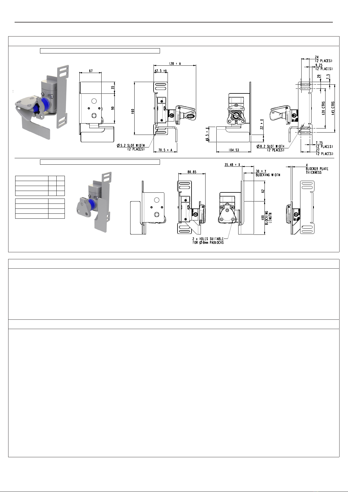
Options & Ordering Information
Description Part No.
Bravo Device for left-hand blocking, with 100mm Blocker
Plate and right-angled mounting bracket BRV2A-1-1-CLSL-MP1
Bravo Device for right-hand blocking, with 100mm Blocker
Plate and right-angled mounting bracket BRV4A-1-1-CLSL-MP1
Bravo device for left-hand blocking, with 50mm Blocker Plate
and right-angled mounting plate BRV2A-2-1-CLSL-MP1
Bravo device for right-hand blocking, with 50mm Blocker
Plate and right-angled mounting plate BRV4A-2-1-CLSL-MP1
Bravo device for left-hand blocking, with 50mm Blocker Plate
plus 20mm extension and right-angled mounting plate BRV2A-3-1-CLSL-MP1
Bravo device for right-hand blocking, with 50mm Blocker
Plate plus 20mm extension and right-angled mounting BRV4A-3-1-CLSL-MP1
Bravo device for left-hand blocking, with 100mm Blocker
Plate and right-angled mounting plate plus 20mm width BRV2A-1-1-CLSL-MP2
Bravo device for right-hand blocking, with 100mm Blocker
Plate and right-angled mounting plate plus 20mm width BRV4A-1-1-CLSL-MP2
Bravo device for left-hand blocking, with 50mm Blocker Plate
and right-angled mounting plate plus 20mm width BRV2A-2-1-CLSL-MP2
Bravo device for right-hand blocking, with 50mm Blocker
Plate and right-angled mounting plate plus 20mm width BRV4A-2-1-CLSL-MP2
Bravo device for left-hand blocking, with 50mm Blocker Plate
plus 20mm extension and right-angled mounting plate plus
20mm width
BRV2A-3-1-CLSL-MP2
Bravo device for right-hand blocking, with 50mm Blocker
Plate plus 20mm extension and right-angled mounting plate
plus 20mm width
BRV4A-3-1-CLSL-MP2
Bravo device for left-hand blocking, with 100mm Blocker
Plate and right-angled mounting plate plus 40mm width BRV2A-1-1-CLSL-MP3
Bravo device for right-hand blocking, with 100mm Blocker
Plate and right-angled mounting plate plus 40mm width BRV4A-1-1-CLSL-MP3
Bravo device for left-hand blocking, with 50mm Blocker Plate
and right-angled mounting plate plus 40mm width BRV2A-2-1-CLSL-MP3
Bravo device for right-hand blocking, with 50mm Blocker
Plate and right-angled mounting plate plus 40mm width BRV4A-2-1-CLSL-MP3
Unique Safety Products | www.uniquesafetyproducts.com | [email protected]

Technical Specication
Construction Materials 316 Stainless Steel and Stainless Steel to BS3146-2:1975 (ANC4B)
Mechanical life 1,000,000 operations
Ambient Temperature -25°C to +80°C*
Shock and Vibration Resistance Tested in accordance with IEC 60068-2-6 and IEC 60068-2-27
Environment Type Indoor & Outdoor
Light Curtain blocking dimensions 100mm x 30mm (See Fig.3 and Fig.4 for details)
Maximum Light Curtain beam spacing 90mm
*The units will only continue to work below freezing point (0°C) where it can be guaranteed that ice will not form on or in the unit; as it will cause the
mechanical parts to bind and jam.
Safety Functions Part No.
Safety Function 1 Prevent unexpected machine restart. BRV
Operating Instructions: Photoelectric Blocking - Bravo
Bravo device for left-hand blocking, with 50mm Blocker Plate
plus 20mm extension and right-angled mounting plate plus
40mm width
BRV2A-3-1-CLSL-MP3
Bravo device for right-hand blocking, with 50mm Blocker
Plate plus 20mm extension and right-angled mounting plate
plus 40mm width
BRV4A-3-1-CLSL-MP3
NOTICE!
Bravo is not an interlock and must only be used in addition to a light curtain as part of a safety related part of a control system
that meets required reliability.
Important:
The Bravo Photoelectric Blocking Device is designed for use according to the installation and operating instructions
enclosed. It must be installed by competent and qualied personnel who have read and understood the whole of this
document prior to commencing installation.
If the Device or guarded machinery equipment is used in a manner not specied by the manufacturer, the protection provided
by the equipment may be impaired.
Any modification to or deviation from these instructions invalidates all warranties.
USP accepts no liability whatsoever for any situation arising from misuse or misapplication of the Device. The Bravo device
alone does not provide any protection from unexpected restart, it must only be used in addition to a compatible light
curtain as part of a complete machine guarding system. The light curtain must meet all relevant safety requirements
and applicable safety standards.
BEWARE OF INTENTIONAL MISUSE CAUSED BY OPERATORS WANTING TO BYPASS SAFETY SYSTEMS. THE
INSTALLER SHOULD ASSESS THE RISKS AND MITIGATE AGAINST THEM.
In order to maintain device safety rating, overall machine guarding system must be validated to EN ISO 13849-2 and/or
evaluated in accordance with IEC 62061.
IF YOU HAVE ANY QUESTIONS OR QUERIES OF ANY NATURE WHATSOEVER PLEASE CONTACT THE SUPPLIER
WHO WILL BE PLEASED TO ADVISE AND ASSIST.
Unique Safety Products | www.uniquesafetyproducts.com | [email protected]

Operating Instructions: Photoelectric Blocking - Bravo
Functionality
The Bravo Photoelectric Blocking Device is to be used to add additional safeguard functionality to an existing machine
guarding or access point that is tted with a Light Curtain or similar Photoelectric or Sensing safety device.
The Bravo device consists of a Blocker Plate, a Personnel / Safety Key and a Padlockable Dustcover (See Fig.1 and Fig.2).
The Blocker Plate is directly linked to the operation and removal of the Personnel / Safety Key such that when the Personnel /
Safety Key is rotated clockwise the Blocker Plate also rotates into an Engaged position. The Engaged position of the Blocker
Plate is designed to block and interrupt the beam or signal of an associated Light Curtain or similar Photoelectric sensing
device.
Once the Blocker Plate is in the Engaged position the Personnel / Safety Key can be removed. The removal of the Personnel
/ Safety Key traps the Blocker Plate in its Engaged position until the Personnel / Safety Key is returned and rotated
anticlockwise back to its original position.
With the Blocker Plate in the Engaged position and the Personnel / Safety Key removed, Padlocks can be added to the
Padlockable Dustcover of the Bravo device for additional Lock-Out functionality. The addition of padlocks to the Padlockable
Dustcover will prevent the Personnel / Safety Key from being re-inserted therefore further retaining the Blocker Plate in its
Engaged position.
Blocking a Light Curtain or similar Photoelectric Sensing device:
• Rotate the Personnel key of the Bravo device clockwise.
• This will rotate the Blocker Plate to its engaged position.
• The Personnel Key can now be removed to trap the Blocker Plate in its engaged position.
Unblocking a Light Curtain or similar Photoelectric Sensing device:
• Raise and open Padlockable Dustcover of Bravo lock barrel.
• Be aware that any padlocks or Lock-Out measures having been used on the Padlockable Dustcover must be removed
before the Dustcover can be opened.
• Insert and rotate the Personnel Key anti-clockwise.
• This will rotate the Blocker Plate to its retracted position.
Figure 1: Operating Positions for BRV2A, Left-Hand Blocking Device -
FORTRESS
A company
Halma
www.fortressinterlocks.com
THE COPYRIGHT OF THIS DRAWING BELONGS TO FORTRESS INTERLOCKS Ltd.
THE CONTENT OF THIS DRAWING IS CONFIDENTIAL AND MUST NOT BE
DISCLOSED TO ANY 3rd PARTY WITHOUT SPECIFIC, WRITTEN APPROVAL.
ALL DIMENSIONS
ARE IN mm UNLESS
OTHERWISE STATED A3 SCALE: 0.70 SHEET: 2 OF 2
ORIGINAL SIZE DATE: 03-02-2021 ISSUE: 0
PBL - PHOTOELECTRIC BLOCKING DEVICE DWG NO: SD-00026
PERSONNEL / SAFETY KEY REMOVED.
BLOCKER PLATE IN ENGAGED POSITION.
PADLOCKABLE
DUSTCOVER
PERSONNEL / SAFETY KEY ROTATED CLOCKWISE.
BLOCKER PLATE IN RETRACTED POSITION.
DEVICE.
SIDE OF PBL
MOUNTED TO THIS
(OR SIMILAR)
LIGHT CURTAIN
MOUNTING PLATE
PERSONNEL / SAFETY KEY ROTATED ANTI-CLOCKWISE.
BLOCKER PLATE IN ENGAGED POSITION.
BLOCKER PLATE
PERSONNEL / SAFETY KEY
BRV
Unique Safety Products | www.uniquesafetyproducts.com | [email protected]

Operating Instructions: Photoelectric Blocking - Bravo
Figure 2: Operating Positions for BRV4A, Right-Hand Blocking Device -
FORTRESS
A company
Halma
www.fortressinterlocks.com
THE COPYRIGHT OF THIS DRAWING BELONGS TO FORTRESS INTERLOCKS Ltd.
THE CONTENT OF THIS DRAWING IS CONFIDENTIAL AND MUST NOT BE
DISCLOSED TO ANY 3rd PARTY WITHOUT SPECIFIC, WRITTEN APPROVAL.
ALL DIMENSIONS
ARE IN mm UNLESS
OTHERWISE STATED A3 SCALE: 0.70 SHEET: 2 OF 2
ORIGINAL SIZE DATE: 22-02-2021 ISSUE: 0
PBL4A - RIGHTHAND FACING PHOTOELECTRIC BLOCKING DEVICE DWG NO: SD-00031
PERSONNEL / SAFETY KEY REMOVED.
BLOCKER PLATE IN ENGAGED POSITION.
PADLOCKABLE
DUSTCOVER
PERSONNEL / SAFETY KEY ROTATED CLOCKWISE.
BLOCKER PLATE IN RETRACTED POSITION.
LIGHT CURTAIN
(OR SIMILAR)
MOUNTED TO THIS
SIDE OF PBL
DEVICE.
MOUNTING PLATE
PERSONNEL / SAFETY KEY ROTATED ANTI-CLOCKWISE.
BLOCKER PLATE IN ENGAGED POSITION.
BLOCKER PLATE
PERSONNEL /
SAFETY KEY
Figure 3: Dimensional Drawing for BRV2A, Left-Hand Blocking Device -
FORTRESS
A company
Halma
www.fortressinterlocks.com
THE COPYRIGHT OF THIS DRAWING BELONGS TO FORTRESS INTERLOCKS Ltd.
THE CONTENT OF THIS DRAWING IS CONFIDENTIAL AND MUST NOT BE
DISCLOSED TO ANY 3rd PARTY WITHOUT SPECIFIC, WRITTEN APPROVAL.
ALL DIMENSIONS
ARE IN mm UNLESS
OTHERWISE STATED
A3
SCALE:
0.40
SHEET:
1 OF 2
ORIGINAL SIZE
DATE:
11-06-2021
ISSUE:
0-A
BRAVO - BRV2A PHOTOELECTRIC BLOCKING DEVICE
DWG NO:
SD-00027
PERSONNEL / SAFETY KEY TURNED, BLOCKER PLATE RETRACTED
PERSONNEL / SAFETY KEY REMOVED, BLOCKER PLATE ENGAGED
MOUNTING TYPE A
MP1 0
MP2 20
MP3 40
BLOCKER TYPE X Y
BRV2A-1 0 0
BRV2A-2 20 20
BRV2A-3 40 20
SEE TABLES BELOW FOR ALTERNATE PLATE DIMENSIONS
BLOCKER PLATE
IN RETRACTED POSITION
BLOCKER PLATE
IN ENGAGED POSITION
BRV
Unique Safety Products | www.uniquesafetyproducts.com | [email protected]

Operating Instructions: Photoelectric Blocking - Bravo
Figure 4: Dimensional Drawing for BRV4A, Right-Hand Blocking Device -
FORTRESS
A company
Halma
www.fortressinterlocks.com
THE COPYRIGHT OF THIS DRAWING BELONGS TO FORTRESS INTERLOCKS Ltd.
THE CONTENT OF THIS DRAWING IS CONFIDENTIAL AND MUST NOT BE
DISCLOSED TO ANY 3rd PARTY WITHOUT SPECIFIC, WRITTEN APPROVAL.
ALL DIMENSIONS
ARE IN mm UNLESS
OTHERWISE STATED A3 SCALE: 0.40 SHEET: 1 OF 2
ORIGINAL SIZE DATE: 11-06-2021 ISSUE: 0
BRAVO - BRV4A PHOTOELECTRIC BLOCKING DEVICE DWG NO: SD-00045
PERSONNEL / SAFETY KEY TURNED, BLOCKER PLATE RETRACTED
PERSONNEL / SAFETY KEY REMOVED, BLOCKER PLATE ENGAGED
MOUNTING TYPE A
MP1 0
MP2 20
MP3 40
BLOCKER TYPE X Y
BRV4A-1 0 0
BRV4A-2 20 20
BRV4A-3 40 20
SEE TABLES BELOW FOR ALTERNATE PLATE DIMENSIONS
BLOCKER PLATE
IN RETRACTED POSITION
IN ENGAGED POSITION
BLOCKER PLATE
Tools and Fixings Required
• Minimum 2 x M8 screws or 2 x M5 screws for securing Bravo device.
• Screws must be suitable length for a minimum of 10mm thread engagement.
• Screws must be security type to prevent unauthorised removal or tampering.
• Required torque setting; 40 Nm.
• 2 x M8 or 2 x M5 Nut / T-Nut / Threaded Hole for securing Bravo device.
• Driver suitable for securing M8 or M5 screws.
•Adhesive Threadlocker to secure mounting xings from loosening due to vibration.
Mounting
1. Locate the Bravo device so that it can correctly interrupt or block the signal of the associated Light Curtain or Photoelectric
sensing device to which it is mounted with its Blocker plate in its engaged position. See Fig.2 for mounting dimensions.
2. Secure the Bravo device using minimum 2 x M8 or 2 x M5 screws through the available mounting holes at the top and
bottom of its mounting plate.
3. Perform Mechanical Function tests before completing installation and commission. See Mechanical Function test section
for more details.
Mount the complete device only in the correctly assembled condition.
•All mounting surfaces should be at, stable and suitable of providing a minimum of 10mm thread engagement or sufcient
support to either an M8 Nut/T-Nut or M5 Nut/T-Nut.
• The Bravo device must be located so that all scheduled inspection and maintenance procedures are all easily possible.
• The complete machine guarding installation must conform to all relevant design, construction and installation standards
and guidelines.
• Any gap around the perimeter of the machine and guarding when under operation (Safety Outputs High) must not exceed
the limits specied in ISO 13857 & ISO 14120.
•All xing screws used to mount the complete Device must be permanently prevented from removal. If mounting xings
are visible, they must be secured against removal by personnel using standard tools, manipulation and un-authorised or
un-identiable removal. If mounting xings are not visible or hidden, they must be secured against removal or loosening
due to vibration. In both cases, a middle strength adhesive threadlocker is required.

Operating Instructions: Photoelectric Blocking - Bravo
Mechanical Function Test Instructions
Test 1
1. Rotate and remove the Personnel key from the Bravo device.
• It must not be possible to rotate and remove the Bravo Blocker Plate from its Engaged position with the Personnel
Key removed.
• The safety output from the associated Light Curtain or Photoelectric sensing device must indicate that the sensing
beam or zone is blocked or interrupted.
• It must not be possible for a machine restart signal to be generated until the Personnel Key has been reinserted
and rotated.
Service and Inspection
Regular inspection of the following is necessary to ensure trouble-free, lasting operation:
• Correct operating function
• Secure mounting of components
• Debris and wear
• WD40 lubricant or equivalent, should be applied to each mechanical element every 10,000 operations, or sooner, to ensure
smooth product operation and function. There are no user serviceable parts in this product. If damage or wear is found with
an assembly, please contact a USP Representative for a replacement. The complete device must be replaced after 1
million operations.
Disposal
This device does not contain any certied hazardous materials so should be disposed of as industrial waste. Electrical items
should not be disposed of in general waste and must be appropriately recycled.
Liability Coverage is Voided Under the Following Conditions:
• If these instructions are not followed.
• Non-compliance with safety regulations.
• Installation and electrical connection not performed by authorised personnel.
• Non-implementation of functional checks.
Protection Against Environmental Inuences
A lasting and correct safety function requires that the device be protected against the ingress of foreign bodies such as swarf,
sand, blasting shot, etc. The device is to be mounted away from the machine, or by the use of anti-vibration mountings, in
order to avoid the effects of vibration, shock and bump.
Use in Dusty Environments: Careful product selection is required, which is best performed under the guidance of a USP
Representative, in order to assess the dust type and product style required.
Use in Corrosive Environments: Careful product selection is required, which is best performed under the guidance of a USP
Representative.
The manufacturer reserves the right to modify the design at any time and without notice.
This guide should be retained for future reference.
January 2022 - v1.0
Unique Safety Products | www.uniquesafetyproducts.com | [email protected]
This manual suits for next models
15