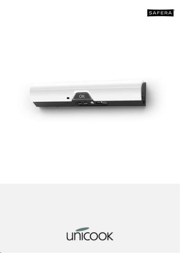
SAFERA Airis BT Operating manual

22105_01B
User and Installation Manual
Airis BT | Airis WiFi | Airis AQ
Powered by

1. Introduction
Congratulations for buying the Unicook
Stove Guard.
This guide describes the use, installation
and maintenance of the three versions of
the product: Unicook Airis BT, Airis WiFi
and Airis AQ.
Before reading, please check the Safera
website for an updated version of this user
manual: www.safera.com/support.
We wish you safe and enjoyable cooking.
1.1 Manufacturer Information
The product is designed and manufac-
tured by Safera, a Finnish company of ex-
perts in smart cooking.
1.2 Distributor
Unicook Ltd
Unit 1, Villa Farm
Tunbridge Wells
Kent, TN3 9UN
Support produit
Tél.: 01 86 65 01 26
Contents
1. Introduction
2. Information and Warnings
3. Main Features
4. Installation
5. Optional: Pairing with Safera Power
Control (PCU)
6. Maintenance
7. Troubleshooting
8. Technical Speciications
9. For private households in EU:
Information on Disposal for Users of
WEEE
10. Conformity
11. Firmware License Terms and Conditions

2. Information
and Warnings
Follow these instructions carefully and
pay particular attention to the instructions
marked in the following way:
ѥWARNING
Follow instructions marked with a warn-
ing accurately to prevent injury to per-
sons and damage to property.
⚐ATTENTION
Follow instructions marked with a note
carefully to prevent damage to property.
ѧHINT
Hints give you useful hints on using the
appliance.
2.1 General Warnings
ѥWARNING
This device is designed to EN 50615 Cat-
egory B - prevention of ires originating
from overheating of oil in pans and pots
on a hob. This device may not be suit-
able for ires originating from lammable
materials left in proximity of the hob or
on the hob. This device may not be suit-
able for ires originating from oven.
Using Unicook stove guard does not
remove your responsibility of safe cook-
ing. Read chapter 10 and 11 carefully for
limitations.
Unicook stove guard does not replace
statutory home ire alarms. Ensure that
ire safety at your home follows the local
regulations.
Flame cooking is prohibited under the
cooker hood. Also, operating gas stove
burners without pans is prohibited.
Unicook stove guard is meant for house-
hold use only. The appliance must not
be used in professional kitchens or with
cookers and hobs meant for professional
use.
Unicook stove guard is not user service-
able. For safety and reliability reasons,
do not disassemble the product. Con-
tact Safera for all service needs.
Unicook stove guard controls the stove
and/or oven only if it is equipped and
correctly coupled with the optional Pow-
er Control Unit (PCU).
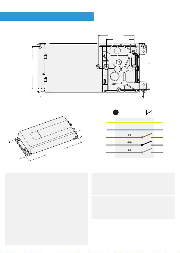
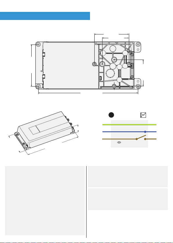
2.2 Additional warnings when
paired with optional Power Control
Unit (see chapter 5.)
ѥWARNING
All electrical connections must be car-
ried out by a qualiied electrician.
If the connection cord is damaged, it
must be replaced by the service person-
nel of the manufacturer or their repre-
sentative to avoid hazards.
If the appliance was stored in a cold
space, it must be allowed to warm up to
room temperature before connecting it
to mains power.

2.4 Laser Safety Information
The Unicook Airis AQ contains two laser
light sources:
1. Class 1 laser as part of the optical dis-
tance and gesture detection system. This
is an invisible infrared laser, similar to
commonly used autofocus lasers in (cell
phone) cameras. It is directed from the
sensor lens area towards the stove area.
2. Class 3R laser as part of the air quality
sensor system. This rating applies only in a
case where This laser is inside the product
and not directly visible for the user dur-
ing normal operation. Diused relections
may be seen if the battery cover / mount-
ing bracket is removed. Do not stare into
these relections closely or inspect them
with optical instruments. Care must be
taken to not damage or disassemble the
sensor unit so that the laser source be-
comes fully exposed. In case of acciden-
tal enclosure damage which fully exposes
the visible red laser beam, avoid direct eye
exposure to the beam and do not inspect
it with optical instruments. In such case,
remove the batteries and discontinue the
use of the product.
2.3 Battery Safety Information
ѥWARNING
Failure to follow the instructions below
may cause the batteries to leak luid and
gas, or even explode:
• Do not expose batteries to excessive
heat, insert them with wrong polarity,
or try to recharge them.
• Always replace all batteries at once,
using the same make, model and age
for all batteries.
• Do not leave empty batteries inside the
device for prolonged periods.
• Recycle the empty batteries according
to local regulations, do not place in
domestic waste.
• If the leaked luid gets into your eyes,
do not rub them, as there is a risk
of losing eyesight. Rinse your eyes
with water and contact a physician
immediately.
• If the leaked luid gets into your
mouth, rinse with water and contact a
physician immediately.
• If the leaked luid gets on your skin or
clothes, rinse with copious amounts of
water to prevent burns.
CLASS 1
LASER PRODUCT
CLASS 3R
LASER PRODUCT

3. Main Features
3.1 Cooking smoke and ire
prevention
Unicook Airis monitors the cooktop (a
hob or free-standing cooker) and cuts the
power if it detects a potentially dangerous
cooking situation.
The Safera mobile app must be used if the
Sensor is not to be mounted at the height
set as the factory default (see chapter 4.4).
The app is not required following installa-
tion.
3.2 Status indicators
LED color Sound Function
Red
blinking
three
times, fast
Yes,
high
pitch
Cooker danger
Red
blinking
three times
Yes,
low
pitch
3-tone
Battery low
Blue
blinking,
continuous
No The sensor
is looking for
a Bluetooth
connection to a
mobile phone
Blue light,
constant
No Sensor Unit is in
software update
mode. Keep your
mobile phone
close and do not
shut down the
Safera App during
software update.
Green
light,
constant
No Sensor Unit is
entering software
update mode. If
the green light
does not turn blue
in two minutes,
remove and re-
insert batteries.
Purple
light,
constant
No Sensor Unit
is in Optional
Accessory Pairing
Mode
Yellow
light,
constant
No Factory reset in
progress, may
take a couple of
minutes

4.1 Check the Delivery Contents
The following components should be in-
cluded:
1. Sensor unit and batteries (3 x AA)
2. Wall mount bracket (pre-installed)
3. Cooker hood mount bracket (not installed)
4. This user manual
❸
❶
❷
OK Button
Mounting tape
protectors (3 pcs)
Extra buttons 1 & 2
Sensors
4. Installation

PCU10.2.-F
2-phase connection with ixed
installation.
See pages 12-17.
PCU6.1F
Fixed 1-phase connection.
See pages 10-11.
PCU6.3F
Fixed 3-phase connection.
See pages 8-9.
4.2 Installation of Power Control
Units (Optional)

PCU6.3F - Installation
Fixed 3-phase connection.
42 mm
239 mm
113 mm
225,5 mm
78 mm
60 mm
60 mm
95 mm
OUTIN
PE
N
L1
L2
L3
PE
N
L
L
L
MAX 16A
MAX 16A
MAX 16A
MICRO DISCONNECTION
ѥWARNING
Turn the power o at the isolation switch
and ensure that all rings, and if relevant
the oven, are turned o.
The supply to the hob/cooker is always
energised when the PCU is connected to
the mains power.
Do not install the power control unit
where it will be exposed to excessive
heat: See operational ambient tempera-
ture for the power control unit Ⓒ.
⚐ATTENTION
The PCU must be installed in a position
where it cannot become damp or wet.
The PCU can be installed behind an oven
below a hob, under a plinth or in a kitch-
en cupboard.

OFF
1
L3
L2
L1
IN
OUT
IN
OUT
IN
OUT
N
PE
OUT
5
IN
Phase order can be freely chosen. If only two phases are
used, connect them to the terminals L1 and L2.
2
6
4
3
4xA
A
A
A
B
2xB
IN

PCU6.1F - Installation
Fixed 1-phase connection.
OUTIN
PE
L/N
L
PE
N
L
230 V MAX. 35 A
MICRO DISCONNECTION
42 mm
239 mm
113 mm
225,5 mm
78 mm
60 mm
60 mm
95 mm
ѥWARNING
Turn the power o at the isolation switch
and ensure that all rings, and if relevant
the oven, are turned o.
The supply to the hob/cooker is always
energised when the PCU is connected to
the mains power.
Do not install the power control unit
where it will be exposed to excessive
heat: See operational ambient tempera-
ture for the power control unit Ⓒ.
⚐ATTENTION
The PCU must be installed in a position
where it cannot become damp or wet.
The PCU can be installed behind an oven
below a hob, under a plinth or in a kitch-
en cupboard.

OFF
12
6
4xA
A
A
A
B
42xB
3
L OUT
N
N
L
OUT
IN
IN
PE
5
OUT
X
IN

PCU10.2F - Installation
2-phase connection with ixed installation.
63 mm
122 mm
231 mm
OUTIN
PE
L1
L2/N
PE
L1
L2/N
208-240 V MAX. 50 A
50-60 Hz
195 mm
140 mm
ѥWARNING
Turn the power o at the isolation switch
and ensure that all rings, and if relevant
the oven, are turned o.
The supply to the hob/cooker is always
energised when the PCU is connected to
the mains power.
Do not install the power control unit
where it will be exposed to excessive
heat: See operational ambient tempera-
ture for the power control unit Ⓒ.
⚐ATTENTION
The PCU must be installed in a position
where it cannot become damp or wet.
The PCU can be installed behind an oven
below a hob, under a plinth or in a kitch-
en cupboard.

A
A
A
A
A
A
B
B
B
B
IN
OUT
Ground wire is
connected to
the cover.
6Connect the plug
(IN) to the wall
socket.
3Connect the OUT and IN cables to the
screw terminals (cables not included).
26xA
Remove the
cover to access
internal wiring.
46xA
Replace the cover.
54xB
Mount the
power control
unit Ⓒ on the
wall behind
the cooker or
into the cabi-
net next to
the cooker.
Connect
the stove
plug to the
power control
unit (OUT).
7
Take o
fuses to
the stove.
OFF
1
ON
8
L2/N
PE
IN
L1
PE
OUT
IN

1
2
4.3 Power up the Sensor Unit
Detach the wall mount bracket to uncov-
er the battery compartment by pulling it
gently open. The bracket is held in place
by magnets. Install the supplied batter-
ies, noting their polarity. The Sensor Unit
should now power up.
4.4 Mount the Sensor Unit
There are two alternative mounting loca-
tions:

Sensors’
ield of view
Sensors’
ield of view
Cooker hood
1. Wall / splashback
Use the wall mount bracket (installed by
default). The Sensor Unit should be in-
stalled levelled, so that the sensors are
pointing downwards towards the stove.
2. Extraction hood underside
Use the cooker hood bracket (separate in
the delivery box). The Sensor Unit should
be installed levelled at on the bottom of
the cooker hood. The front edge of the
Sensor Unit should be mounted near the
front of the hood, vertically in-line with the
front edge of the front cooking rings with
OK-button facing the user.
For the most up to date mounting method
and stove support information, please re-
fer to the “Installation Wizard” -section in
the Safera App. For the factory shipped
software version, the allowed mounting
height speciications are:
Installation Height
Wall mount, stove width up
to 60 cm
50 cm
± 5 cm
Wall mount, stove width
from 60 cm to 90 cm
60 cm
± 5 cm
Cooker hood mount,
electric hob width up to
60 cm
45 - 85 cm
Cooker hood mount,
electric hob width from 60
cm to 90 cm
55 - 85 cm
Cooker hood mount, gas
hobs
75 - 85 cm
Without changing any settings (and there-
fore using the mobile app), the sensor can
be mounted in the following positions.
• Wall mount, electric stove width up to
60 cm -- mounting height: 50 cm ± 5
cm
• Cooker hood mount, electric stove
width up to 60 cm -- mounting height:
60 cm ± 5 cm
Mounting height is measured from the
stove surface to the top of the Sensor Unit
enclosure.
The maximum supported stove width is
90cm.

Mounting guide:
1. Select the most suitable mounting
method and place the appropriate
mounting bracket on the sensor unit.
2. Make sure that there is no obstruction
in the sensors’ ield of view between
the selected Sensor Unit location and
the stove.
3. Make sure that the mounting location
is free of direct sunlight and other
sources of powerful light and heat.
4. Thoroughly clean the mounting
location surface.
5. Mark the exact position to the mounting
location.
6. Remove the red protection strip(s)
covering the adhesive tape(s) on the
mounting bracket and irmly place the
Sensor Unit into the marked location.
4.5 Connect to Safera Mobile App
with Bluetooth
Please install the Safera App to your mo-
bile phone. The App is needed for initial
setup, irmware updates, coniguration
and advanced features (Smart Cooking
and Air Quality).
Connecting Safera App with Unicook Airis:
1. Download and install Safera App to
your mobile phone (search for “Safera
App” in the App Store or Play Store).
2. Open the Safera App and choose
“Connect to a New Safera Sense”.
3. Press the OK-button on the Sensor Unit.
4. “Safera” or “Safera Sense” should
appear on the list. Select it by touching.
5. If asked for Bluetooth pairing, answer
to allow it.
6. If asked for Sensor Unit Firmware
Update, allow it. This is very important
in order to ensure that the product’s
performance is up to date.
7. Go to the “Installation Wizard” -section
in the Safera App (this section may also
launch automatically at this point). The
App will guide you through questions
regarding your kitchen and stove type
and then automatically conigures the
Safera Sense for your environment.

5. Pairing with Safera
Power Control (PCU)
5.1 Pairing with PCU
1. Install a Safera Power Control unit as
instructed in chapter 4.2 and then
continue the pairing from the step 2
below.
2. Switch o the power at the isolation
switch.
3. Press button 1 for ive seconds until you
hear a signal and OK-button is lit blue.
4. Switch on the power at the isolation
switch. The Power Control Unit will now
contact the Sensor unit which gives a
sound signal (•••).
5. Open Safera App and go to the “Install a
new Safera Sense” section (this section
may launch automatically at this
point). The App will guide you through
the setup with questions about your
Unicook Airis sensor installation and
type of hob.
5.2 Check the working order
1. Turn on one cooker plate with maximum
power. With an induction cooker use a
suitable dish.
2. Press and hold the OK-button for 5
seconds: the system should cut o the
cooker power.
3. Test that none of the cooker plates and
oven (if connected to the stove guard)
are operable: if ok, switch o cooker
and oven.
4. Return the cooker power by pressing
the OK-button: the Indicator Light
should blink green once. If not, see
Troubleshooting in chapter 8.
5. Working order checked successfully:
Date Installer
ѥWARNING
If you are replacing the cooker or the
power control unit, pair the power con-
trol unit again and run the “installation
wizard” in the mobile app again.
Extra buttons
1 & 2

6. Maintenance
6.1 Regular maintenance
To ensure continued safe and reliable op-
eration, follow these maintenance instruc-
tions at least once every three months or
more frequently if needed:
1. Press the OK-button to perform self-
diagnostics: when the Sensor Unit is in
working order, the indicator light will
blink in green. Any other color indicates
a problem – please see section
“Troubleshooting”.
2. If there is visible dirt or grease
accumulation, wipe the Sensor Unit
with a soft cloth moistened with water
or a mild detergent, such as washing
up liquid. Avoid pressing the appliance
buttons and sensors.
6.2 Battery life and low battery
In normal use, the batteries should last 18
months.
The Sensor Unit sounds a beep with an or-
ange indication light when the battery life
is expected to run out soon (typically in a
couple of weeks). Replace the batteries
according to the following instructions.
You may reset the low battery alarm for 12
hours by pressing the OK-button.
If the batteries are not replaced, Unicook
Airis switches itself o when the batteries
are fully depleted. The PCU will also shut
down the electric power to the stove.
6.3 Battery replacement
High-capacity batteries are recommend-
ed such as Varta Industrial.
Remove the sensor unit from the mount-
ing bracket by pulling it gently.
Remove the empty batteries.
Place the new batteries in the sensor unit.
Notice the correct battery orientation
markings inside the battery compartment,
where the “+” symbol denotes the positive
terminal of the battery according to this
picture:
Place the sensor unit back onto the
mounting bracket.

7. Troubleshooting
Press the OK-button to ind out the prob-
lem type. The indicator light:
Blinks in blue Blinks in yellow
Once: Problem
with wireless
connection
between the
Sensor Unit and
the Power Control
Unit (PCU).
Once: Problem
with sensors.
Twice: Problem with
the Power Control
Unit.
Twice: Problem
with sensor unit
electronics or
software.
Three times: Power
Control Unit over-
heating.
Three times:
Faulty installation
position of the
sensor unit: see
remedy on the
table below.
Problem Remedy
Faulty
installation
position of
the Sensor
Unit.
Sensor Unit has detected
that it is not level, or it’s
position has changed
since installation.
If mounted on the cooker
hood, check that the
cooker hood underside
surface is perfectly level.
Also check that the
sensor distance from
the stove is within the
limitations detailed in
chapter 4.3.
The Sensor
Unit
repeatedly
gives false
alarms
Test the working order
according to chapter
5.2. If the product is in
working order, but gives
repeatedly false alarms,
re-run the "Installation
Wizard" in the Safera
App to make sure that
all kitchen and cooker
related parameters are
correct.

8. Technical
Speciications
Model name:
• Model name: Unicook Airis II
Battery type: 3 x AA/LR6 Alkaline
Battery life: 5...18 months depending on
use cases.
Pollution degree: 2
Operational temperature:
• 0 … 50 C (long-term)
• 0 … 70 C (short-term)
Wireless connections:
Bluetooth 5.0 (BLE)
• Range: 10 … 50 meters depending
on mobile phone model and physical
obstructions
• Frequencies used: 2402 … 2480 MHz
• Maximum transmit power: 2 dBm
• Maximum radiated power: 3.5 dBm
802.11 b/g/n Wireless Communication
(Airis AQ and Airis WiFi only, EU Only)
• Frequency range: 2400 MHz ... 2483.5
MHz
• Transmit power:
• 802.11 b: +20 dBm
• 802.11 g: +17 dBm
• 802.11 n: +14 dBm
Safera Wireless 2.0 (Proprietary
protocol for PCUs)
• Range: 10 … 20 meters depending on
construction materials presence
• Frequencies used: 2400…2483.5 MHz
• Maximum transmit power: 2 dBm
• Maximum radiated power: 3.5 dBm
9. For private
households in EU:
Information on
Disposal for Users of
WEEE
This symbol on the product(s)
and / or accompanying docu-
ments means that used electri-
cal and electronic equipment
(WEEE) should not be mixed with general
household waste. For proper treatment,
recovery and recycling, please take this
product(s) to designated collection points
where it will be accepted free of charge.
Alternatively, in some countries, you may
be able to return your products to your
local retailer upon purchase of an equiva-
lent new product.
Disposing of this product correctly will
help save valuable resources and prevent
any potential negative eects on human
health and the environment, which could
otherwise arise from inappropriate waste
handling. Please contact your local au-
thority for further details of your nearest
designated collection point. Penalties may
be applicable for incorrect disposal of this
waste, in accordance with your national
legislation.
This manual suits for next models
2
Table of contents
Other SAFERA Safety Equipment manuals