32
CONTENTS
1.
2.
3.
4.
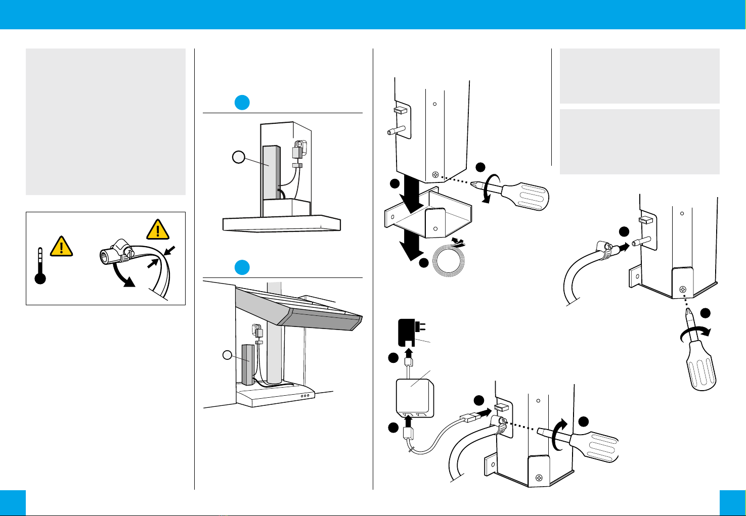
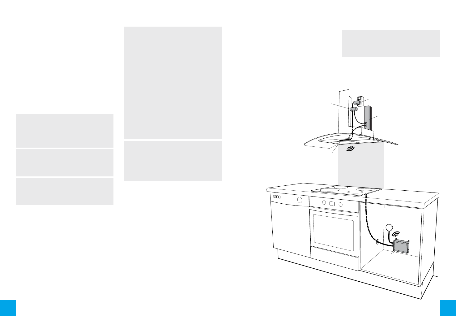
Sensor
ѥWARNING
Follow instrucons marked with a war-
ning accurately to prevent injury to per-
sons and damage to property.
⚐ATTENTION
Follow instrucons marked with a note
carefully to prevent damage to property.
ѧHINT
Hints give you useful advices on using the
appliance.
ѥWARNING
Read user and installaon manual before
using or installing the appliance.
Install and check the applicaon accor-
ding to the instrucons. SAFERA is not
liable for any damages or expenses caused
by inappropriate installaon.
Check that the Stove Guard is compable
with the cooker (see secon 1.1).
If the network cable is damaged, it must
be replaced by the service personnel of
the manufacturer or their representave
to avoid hazards.
All electrical connecons must be carried
out by a qualied electrician.
⚐ATTENTION
If the appliance was stored in a cold spa-
ce, it must be allowed to warm up to room
temperature before connecng it to elec-
tric network.
1.
• Central Unit Ⓐ
• Ⓓ
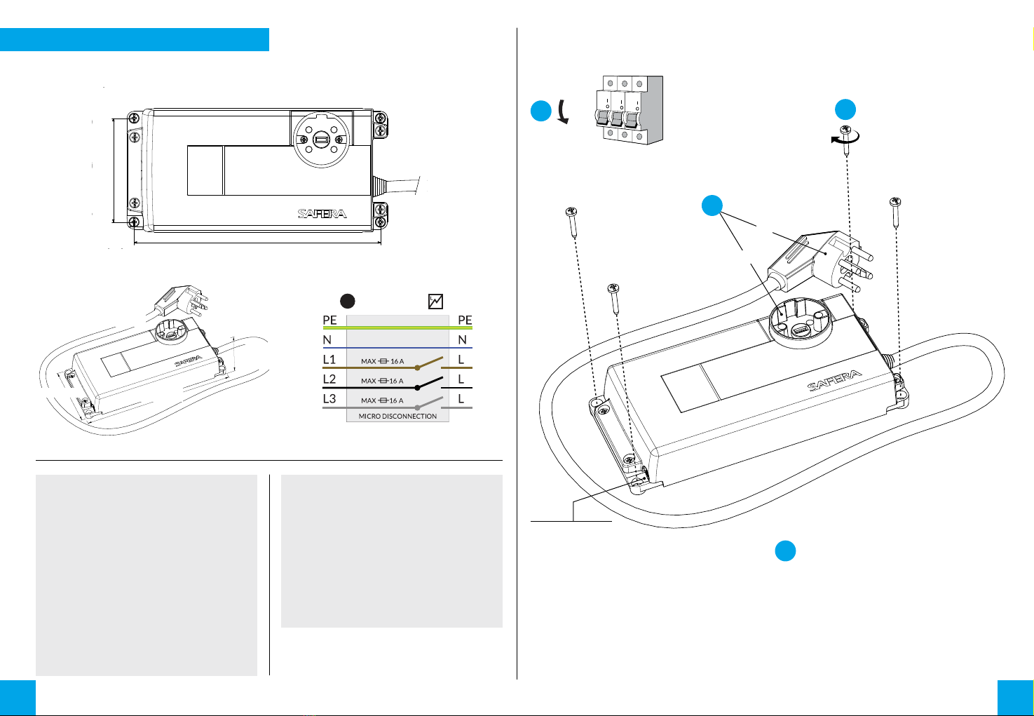
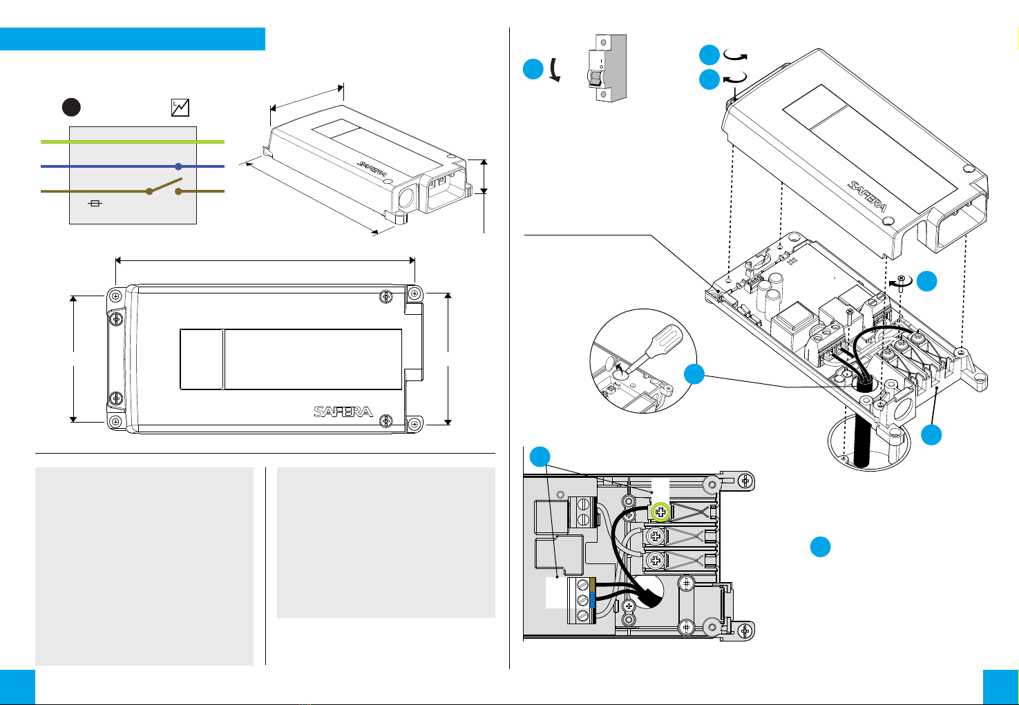
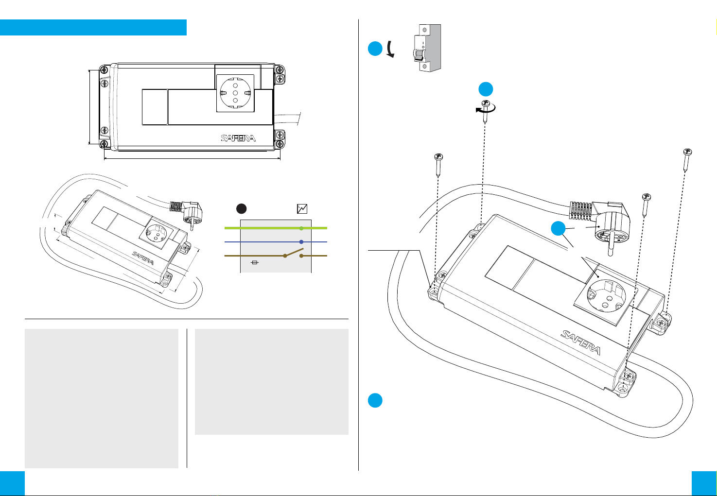
• Power Control Unit Ⓒ
•
•
ѥWARNING
Please contact your vendor if you noce
anything unusual about the appliance.
Ⓒ
Ⓐ
Ⓓ
Ⓔ
Ⓕ