SAFETRON 600 Series User manual

SAFETRON SL620
Installation manual
20231030
EN

2 | Installation manual SAFETRON SL620
The safety features of this product are crucial for its compliance with EN 14846:2008. Modifications or other changes to the instal-
lation and/or products beyond those described in this documentation are not permitted. SAFETRON assumes no responsibility
for products that have not been installed in accordance with the current instructions or if the maintenance instructions are not
followed.
• SAFETRON solenoid locks in the 600 series are electric locks used in doors with normal security requirements. The locks are
available in different designs for different types of usage and security requirements. Solenoid locks are suitable where fast
locking is required and can be used on both light interior doors and heavy exterior doors.
• Fire door rating with reference to test report number: PGA11645A_rev1. The test was performed with a single steel door.
• When used in fire proof doors solenoid locks in the 600 series must be used in conjunction with a certified door.
• Check the door’s fire certificate, if any, to ensure that there are no conditions in the certificate that exclude or restrict the
use of the SL620/SL621/SL630.
• Before installing an electric lock, check that the door is correctly installed and that the door leaf moves freely. It is not
recommended to install SAFETRON solenoid locks in hollow core doors. Check that the door’s construction allows the instal-
lation of a lock, for example by checking hidden hinges, that overlapping doors can be opened at the same time, that the
door gap is 3 mm +/- 1 mm and that moving parts do not affect each other.
• SAFETRON locks may be installed in single doors or double doors made of wood, steel or aluminium. Door weight: over
200kg.
• Locks manufactured according to SS-EN 14846:2008 provide a high degree of reasonable security provided they are fitted to
doors and frames in good condition.
• Consideration must be taken to ensure that any seals or sealing strips do not inhibit the function of the lock.
• Ensure that the correct lock is fitted for the intended door environment (see product catalogue).
• The assembly method does not differ between different types of doors, such as wood/metal.
• Established instructions must be followed carefully during installation. These instructions must be transmitted by the
installer to the user.
• All components specified for the installation must be used to meet the European standard SS-EN 14846:2008.
• Check that the lock latches (when in retracted position) do not prevent the opening and closing function of the door (see
maintenance instructions).
• Where locks are mounted on double doors (double doors) it is required that door closers are used that have a door
coordinator according to EN 1158 (see standard) to ensure the correct closing sequence.
• The products must not be used in doors that can be opened in both directions, such as swing doors.
Read through and follow the installation instructions.
• To ensure a good function, the door gap must be 3mm +/- 1mm.
• Avoid file and emery chips. After the recess has been made in the frame, it must be cleaned properly.
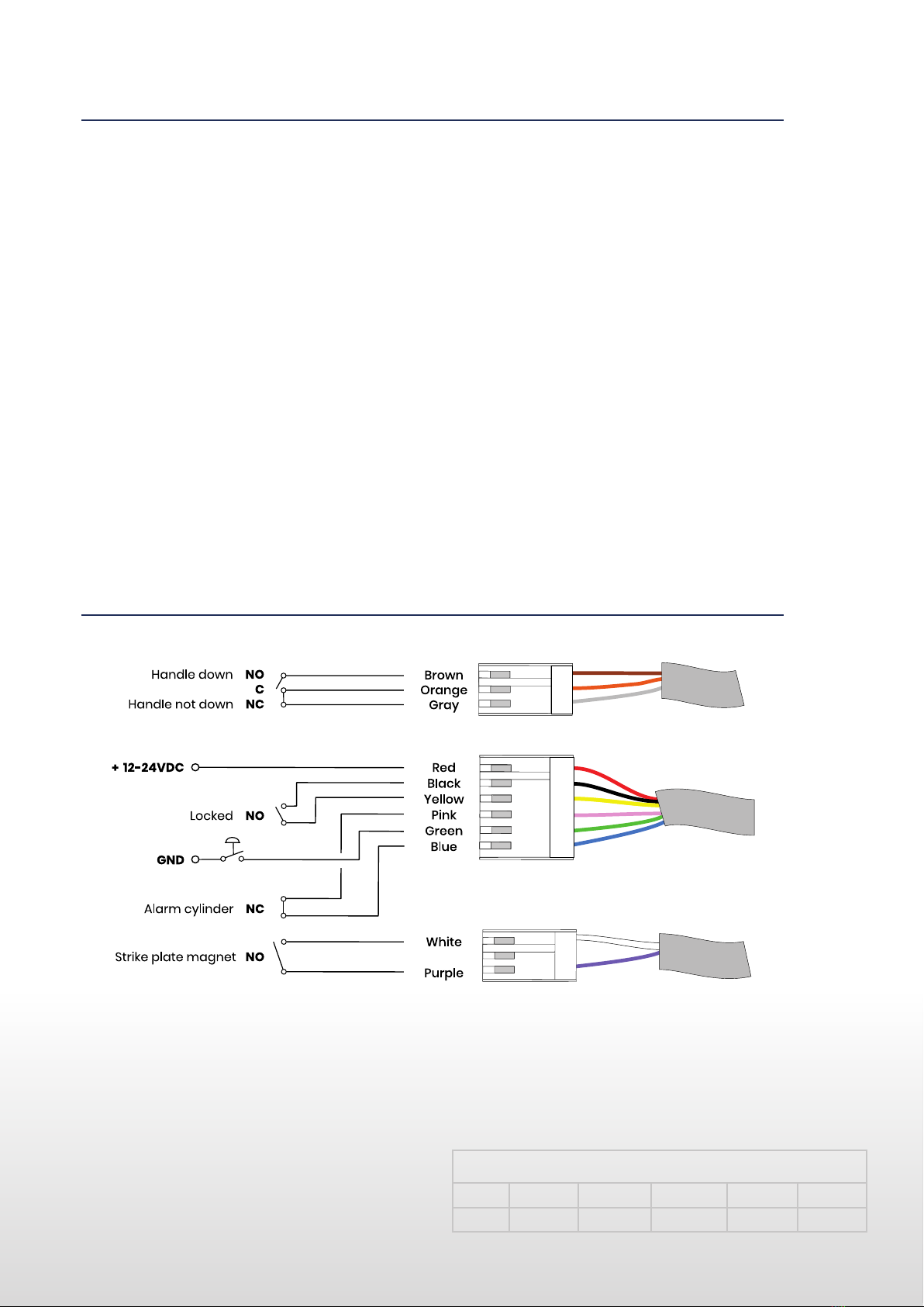
• Ensure that the cable is not pinched or damaged during installation.
• Cable of type data/signal with area less than 0.2 may not be used to supply power to the lock.
• Cable area must be dimensioned based on the conditions that apply.
• When suppling multiple locks/passage systems/readers/central units together the total power consumption must be taken
into account when calculating the cable area.
• The warranty is void in the event of incorrect installation or the use of accessories that are not recommended by
• SAFETRON.
• SAFETRON does not provide a warranty for installations that do not follow the recommendations.
Lock maintenance should be performed by a trained professional. In normal use, the mechanical parts of the lock housing
should be lubricated once a year. Use a lubricant that does not contain graphite or solvents.
• Check that mounted knobs, door handles and cylinders are working satisfactorily. If necessary, lubricate and/or adjust.
• For high-frequency use, the mechanical parts of the lock housing are lubricated as needed.
• The electrical parts of the lock housing are maintenance-free
• Check and adjust if necessary that the door closes correctly. To achieve this, e.g. door hinges as well as door closers need to
be adjusted. A poor door function negatively affects the locking function.
IMPORTANT INFORMATION
INSTALLATION
MAINTENANCE

Installation manual SAFETRON SL620 | 3
SAFETRON locks in the 600 series are electromechanically controlled solenoid locks in modular design,
in power to open or power to lock versions, adjustable for right-/left-hung doors and with or without
split function.
For more information on areas of use and accessories see www.safetron.com.
Technical data
SAFETRON SL620
• Multi current: 12-24VDC
• Power consumption: 40mA
• Working temperature: -25°C till +70°C
• Door sensor: Max 250mA 30VAC/VDC, 10W
SAFETRON SL620 are tested and certified in accordance with EN 14846: 2008
The products meet the following requirements according to SS-EN 14846: 2008
Category
of
use
Durability
and load
on latch
Door
mass and
closing
force
Suitability
for use
on
re / smoke
doors
Safety
Corrosion
resistance
and
temperature
Security
and
drill
resistance
Security
electrical
function
Security
electrical
manupilation
3 X 6 F 0 L 3 1 1
The lock meets the requirements for fire proof doors: 120 min
SAFETRON SL620 together with emergency exit devices 793 and 794 are tested and
certified in accordance with SS-EN 179:2008
The products meet the following requirements according to SS-EN 179:2008
Category
of
use
Durability
Door
mass and
closing
force
Suitability
for use
on
re / smoke
doors
Safety
Corrosion
resistance
and
temperature
Security
Projection
of
operating
element
Type
of
operation
Field of
door
application
3 7 7 B 1 3 5 2 A B/D
Description Art no
Cable C02 (10m) 202144628
Emergency exit device 793 Cr 202144913
Emergency exit device 793 Mcr 202144999
Emergency exit device 793 Mblk 202145000
Emergency exit device 794 H Cr 202144899
Emergency exit device 794 V Cr 202144900
Emergency exit device 794 H Mcr 202144995
Emergency exit device 794 V Mcr 202144996
Emergency exit device 794 H Mblk 202144997
Emergency exit device 794 V Mblk 202144998
Emergency exit device 794-2 Cr 202144991
SAFETRON REC (re-entry card) 202144936
PROPERTIES AND TECHNICAL DATA
ACCESORIES

Recommended cable dimensions
0-10M 11-20M 21-40M 41-80M 81-100M
12-24V 0,17mm² 0,34mm² 0,68mm² 1,36mm² 1,7mm²
WIRING
Split function
Split function means that the door handle on the outside is electrically controlled, while the door
handle on the inside is always mechanically activated, thereby always allowing for a mechanical exit.
This means you don’t need an open button on the inside but instead can always use the door handle
to exit.
Simple function
Both the outside and inside door handles are electrically controlled and thus electrical activation
is always needed for access. On the inside, an open button or a code lock/access control system is
needed, the latter option is advantages if you want to increase the security level even further.
Unlocked
In the unlocked position, both outside and inside door handles are mechanically activated, which
means that the lock can be used mechanically before it is put into operation, e.g. on a construction
site where doors have been installed but before the access control system has been installed.
FUNCTIONS
Cable of type data/tele/signal with areas between 0.1-0.2 must not be used as power supply for the lock.
Safetron does not provide a warranty for installations that do not follow the recommendations. See table
below.
Recommended minimum cable area between power source (transformer, not passage system) and lock
housing (total length)
ATTENTION!
It is important that the power supply to the lock has the right
dimensioned cable to avoid voltage drops that may interfere with
the functionality of the lock. When suppling multiple locks/pas-
sage systems/readers/central units the total power consumption
must be taken into account when calculating the cable area.
4 | Installation manual SAFETRON SL620

The magnet in strike plate is adjusted against the model engraving on the forend of the lock case.
Setting the latch bolt orientation
1. Loosen the locking screw with a 2.5mm hex key.
2. Take out the latch bolt and turn it over.
3. Re-install the latch bolt and fasten the locking screw.
70
SL620
Setting the split function is set via the function selector which has
four distinct positions. The screw has a round marking that indica-
tes the selected function.
Choose Split right for a right-hung door or Split left for a left-hung
door by setting it in the correct position.
To set the lock in simple function where
electric activation is required from both
sides of the door the function selector is
set to the position Locked.
To set the lock in the unlocked state where both sides are mechanically open, set the
functional selector to the position Unlocked.
DOOR SENSOR (STRIKE PLATE MAGNET)
ADJUSTING FOR RIGHT OR LEFT
SETTING THE SPLIT FUNKTION
SET THE LOCK IN SIMPLE FUNCTION
SET THE LOCK IN UNLOCKED SETTING
Installation manual SAFETRON SL620 | 5

”CLASSIC” LATCH POSITION
”MODERN” LATCH POSITION
ADJUSTING THE LATCH POSITION
6 | Installation manual SAFETRON SL620

”CLASSIC” LATCH POSITION
”MODERN” LATCH POSITION
Drawing
SL 620
SL 621
Latch position:
Classic
55,9
17,5
15
6,0
24,6
12
30
5
15
5,50
40,5
150
34,5
3
75
50
5,10
30
30°
225203
22
R11
2 x
5,5
11,2 X 90°
19
Drawing
SL 620
SL 621
Latch position:
Modern
15
17,5
41,85
6,0
55,9
150
75
34,5
40,5
3
30
12
5
15
50
30
30°
5,1
5,50
22
225203
R11
2 x
5,50
11,20 X 90°
DIMENSIONS
Installation manual SAFETRON SL620 | 7

2 - 5,5
12,5
+
-
6,0
6,0
9,6
SAFETRON 105-1
C
L
STRIKE PLATE POSITION
8 | Installation manual SAFETRON SL620

200 120 27
4
R16,5
28
40
42
42
111
50
165
225
22
25
R11
INSTALLATION
Installation manual SAFETRON SL620 | 9

225
3
85
(Lock case depth 75 mm)
50
57111
20
42
42
165
4
25
22
R11
203
11
225
3
85
(Lock case depth 75 mm)
50
57111
20
42
42
165
4
25
22
R11
203
11
DRILLING SCHEME
10 | Installation manual SAFETRON SL620

MAINTENANCE SAFETRON SOLENOID LOCK
• Maintenance should be performed by a trained professional
• Ensure that mounted knobs, handles and cylinders are working
satisfactory
• Lubricate and make adjustments as necessary
• In normal use lubricate the lock housing mechanical parts once a
year. Use a lubricant that does not contain graphite or solvents
• At high frequency use, lubricate mechanical parts as needed
• Lock housing electrical components are maintenance free
• Check that the door closes properly. If necessary adjust door hinges
and/or door closers. A bad door function adversely affects locking
MAINTENANCE
Installation manual SAFETRON SL620 | 11

SAFETRON SL620
SAFETRON AB
Säterivägen 18
P.O. Box 2096
65002 Karlstad
Sweden
The right to changes to the catalog’s content and assortment is reserved. We reserve the right for possible printing
errors. SAFETRON™ is a registered trademark.
Tel: +46 54 19 02 45
info@safetron.com
www.safetron.com
Other manuals for 600 Series
1
This manual suits for next models
3
Table of contents
Other SAFETRON Door Lock manuals
Popular Door Lock manuals by other brands

Dormakaba
Dormakaba 8300 Series installation instructions

SUGATSUNE
SUGATSUNE Lamp GS-GL50 installation manual

iver
iver Backplate Privacy Install instructions

Hafele
Hafele DT 750 operating instructions

Assa Abloy
Assa Abloy Securitron Magnalock M670BD Series installation instructions

Weiser
Weiser Smartcode 5 installation guide