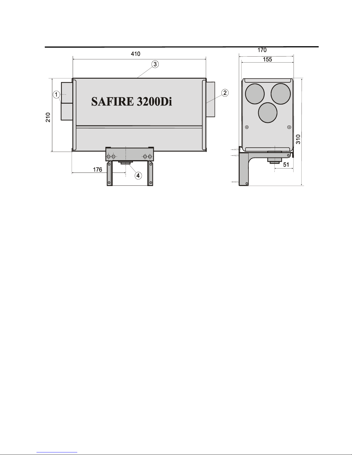
SAFIRE 2400Di, 2600Di, 3200Di and 3600Di Diesel / fuel oil heaters
5
USAGE, INSTALLATION AND MAINTENANCE
January 2011
SF- Lämmitin Oy
Tilhenkatu 1 20610 Turku Finland Puh/Fax +358(0)2-2443282
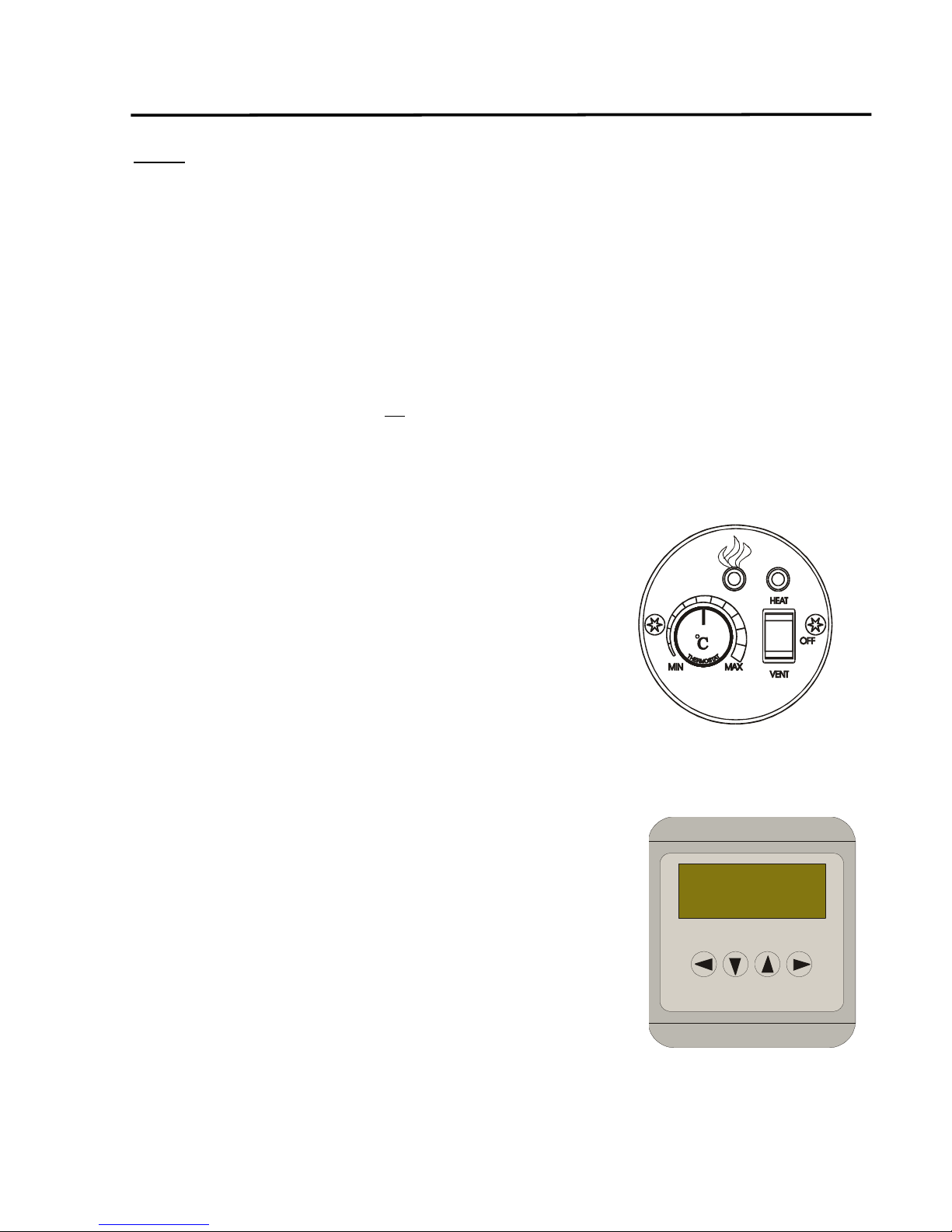
INDICATOR LEDS
Indicator LEDs on the control panel:
Green LED above the switch of the basic control
panel: the heater is on. If the LED is not on when
starting the heater, the heater’s power supply is
probably disconnected.
Green LED (flame) on the control
panel: the flame sensor has detected
a flame and combustion is in process.
Indicator LEDs on the end of the heater:
Green LED D10: the flame sensor
has detected a flame and
combustion is in process.
Yellow LED D2: the voltage is low, under
10,8V (or under 9V during the ignition).
The battery voltage may be too low, the power supply
cables too thin or some connection in the wiring loose.
During the start the voltage can be lower, because the
voltage drop caused by the filament current in the power
supply cables can be up to 0,5V. If the voltage drops
below the limits mentioned above, the aftercooling
mode activates and the heater turns off.
Red LED D9: malfunction detected, the
combustion stops.
On the end of the heater is a display which indicates the
type of malfunction (see Malfunctions; NB: the display is
upside down). If you have turned the heater off, you can
see the latest malfunction type on the display again by
turning the switch to “VENT”: the latest error code
shows on the display.
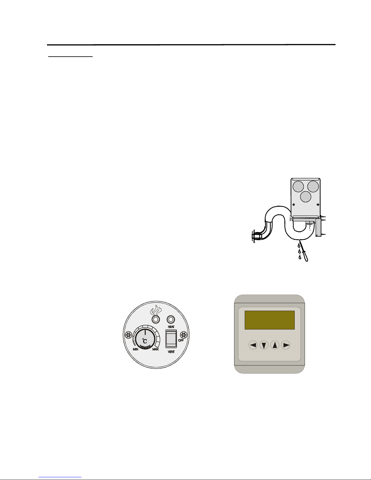
GENIUS CONTROL PANEL
Control the heater according to the instructions
indicated on the GENIUS control panel. The normal
start: Push BACK, the text HEATER CONTROL
appears on the display; push OK, the text START
appears on the display, push OK and the heater starts.
The menu ADJUST POWER allows you to adjust either
the power or the temperature. Choose menu items with
arrow keys, accept with OK.
If you desire extra strong ventilation, choose DRYING
VENTILATE. On this mode the heater takes more fresh
air; this improves the drying effect while the heating
power is low (practical f. ex. in the summer when the air
is damp but not very cold).
Return to the main menu with BACK. NB! All selections
are not allowed in every mode.
STARTING THE HEATER
Start the heater with ON/HEAT-OFF-VENT-switch.
Green LED above the switch turns on. The pump
operates (you can hear tapping, the dot on the circuit
board display blinks), the fans are operating.
Green LED (flame) on the end of the
heater and on the basic control panel
lights about 1 1/2–3 minutes after the
start when the flame sensor has detected
a sufficient flame.
The ignition process ends in about 6 1/2 minutes. The
heater operates on the power set with the thermostat or
with the adjustment knob; the main fan measures the
temperature of the room and operates on sufficient
power.
HEATING POWER
Make sure that the temperature chosen on the
thermostat or the chosen power settings correspond to
your needs.
ADJUSTING THE HEATING POWER
If your heater has a thermostat, it will adjust the power
automatically. If you want to change the heating power
temporarily, adjust the temperature settings; the power
level will change to correspond to the set limit.
If your heater doesn’t have a thermostat, adjust the
power manually with the adjustment knob. NB! The
main fan doesn’t operate on the new power level until
the temperature of the air requires it.
TURNING OFF THE HEATER
Turn the heater off by turning the switch into OFF
position; the pump stops, the heater goes into
aftercooling mode and after that turns off.
Do not cut the power supply off f. ex. from the main
switch when the aftercooling is on process (about 6
1/2 minutes)!
If the power supply is cut off, the heater starts next time
only after it is set on ventilating mode
(error code A).
+ -