Quantum™ ädəsē® RFID Installation Instructions Pg. 4 of 8
Installing the lock trim
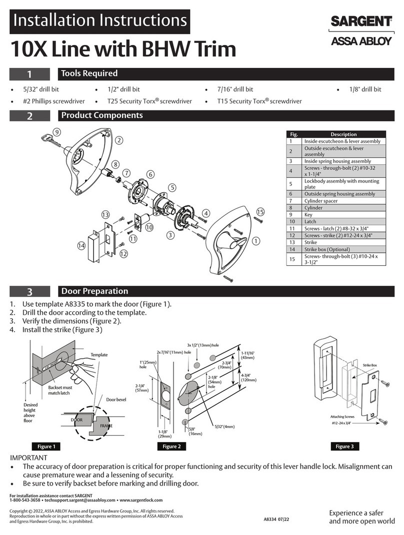
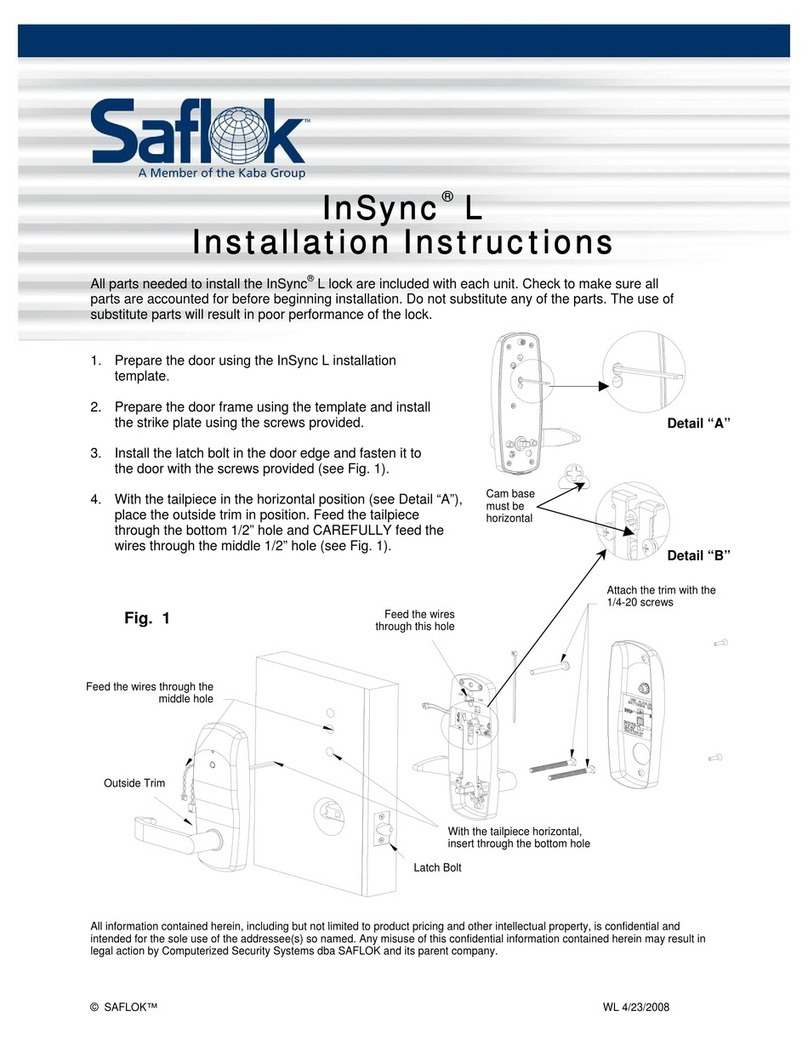
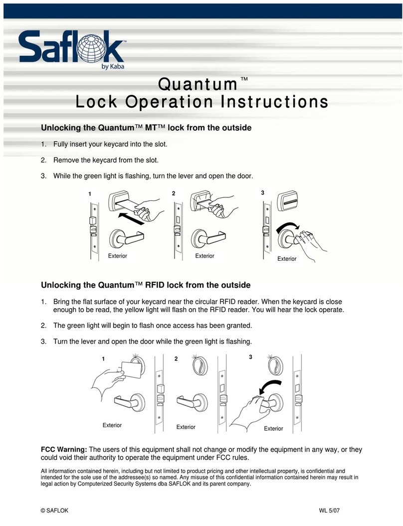
The outside lever trim has two carriage bolts that fit into the diagonal holes in the mortise case. These
carriage bolts establish an accurate trim position with respect to the mortise case assembly, allowing the
levers and bolt mechanism to operate without binding. The holes machined in the door surfaces should
not influence the position of the trim or the proximity reader assembly.
Do not tap or bend the carriage bolts to manipulate the fit of either trim piece during installation. The door
prep holes should accommodate the outside lever trim and the proximity reader assembly. If the carriage
bolts or proximity reader enclosure fit too tightly in the door prep holes, then remove the mortise and
enlarge the holes to achieve a free fit.
1. Remove the battery pack and retaining
spring.
2. Position the outside proximity reader
assembly on the outside of the door (see
Fig. 2). Route the ribbon cable and power
cable through the 13/16” hole in the door.
Do not pull on the ribbon cable.
3. Route the ribbon cable and power cable
through the rectangular hole in the inside
trim. Do not pull on the ribbon cable. This
hole is located above printed circuit board
(PCB) assembly. Route the motor wire
through the wire channel in the inside trim
closest to the door edge. These holes are
located below the PCB (see Fig. 3).
4. Position the inside trim on the inside of the
door.
M5 x 0.8g x 31 mm
Screws
Proximity Reader
Assembly
Fig. 2
Power Cable
Ribbon Cable
Outside Lever
Trim
Motor Wire
Inside Trim
8-32 x 1-1/4
Screws
5. Secure inside trim to the proximity reader
assembly using two M5 x 31 mm screws.
Important: Do not fully tighten the screws at this point.
6. Align the outside lever trim with the diagonal holes located on
either side of the mortise hub and secure it by starting the two
8-32 x 1-1/4 screws (see Fig. 2).
7. Once the outside lever trim is fully secured, check the alignment of
the inside trim and be sure that the both levers rotate without
binding. Once the trim is properly aligned, fully tighten the four
screws that secure the trim to the door and check for proper rotation.
8. Place the battery pack in position above the PCB and secure it in
place using the retaining spring. Be sure that the battery wire is
routed through the lower left corner of the battery compartment.
Motor Wire
Channels
Fig. 3
Route the ribbon
connector through the
rectangular hole
9. Connect ribbon cable and motor cable to the PCB.
© SAFLOK™ INS_QTMADESERFID 2/16/2012


