Saft WSSFCEX-GHC User manual

Thank you very much for choosing Daviteq Wireless Sensors. We are the leading wireless sensor manufacturer in the
World. We have a wide range of wireless sensors which support different connectivity like LoRaWAN, Sigfox, Sub-GHz,
NB-IoT...Please find out more information at this link.
This manual is applied to the following products
Item code
HW Version
Firmware Version
Remarks
WSSFCEX-GHC-01
1
2
Product Features
Connectivity Type
Sigfox
Product Type
1 part
Mounting Type
Wall mount
Powered by
1 x C battery LiSOCl2, recommend SAFT LS26500
Information Changes in this version v.s the previous version
Item
Changes
Changed by
Changed Date
Approved by
Approved Date
1
Initial version
D.Q.Tuan
29-10-2022
N.V.Loc
31-10-2022
To use this product, please refer step by step to the below instructions.
Operating Principle
Uplink Payload
Battery
Connect to Sigfox Network
Installation
Troubleshooting
Configuration
Calibration
Specification
Warranty and Support
Manual for Sigfox-Ready Exd
Approved Flammable Gas Sensor -
WSSFCEX-GHC | FW2
1. Quick Guide
Reading time: 10 minutes

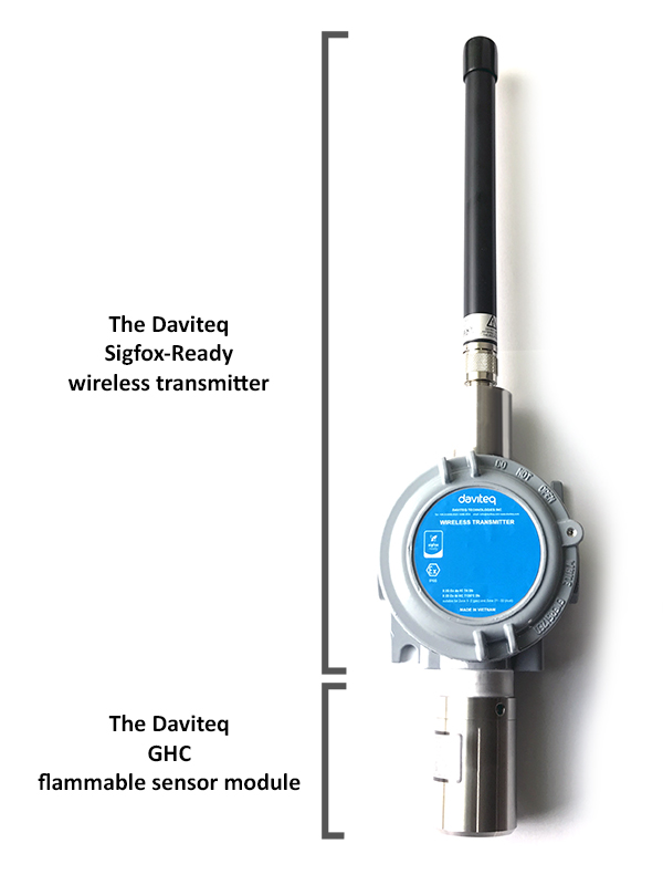
WSSFCEX-GHC is a Sigfox-Ready sensor with Ex d explosion-proof approve and comes with a built-in high-performance
NDIR technology sensor to detect the Hydrocarbon Gas concentration in the air. Ultra-low-power design and smart
firmware allow the complete Wireless and Sensor package to run on a single battery type C for 3-5 years or more with
15 minutes update.
It is battery-operated and able to connect to any Sigfox network in the World. It supports all frequency zones such as
RC1, RC2, RC3c, RC4, RC5, RC6, and RC7.
Please refer to this link for the flammable gas sensor's principal operation.
Please refer to this link for typical applications.
The device will send uplink messages in the following cases:
Case 1: After power-up in the 60s, the device will send the first message called START_UP. The payload will tell
the user the HW version, FW version, and current configuration of the device;
Case 2: Then, in every interval time (pre-configured), for example, 10 minutes, it will send the message called
CYCLIC_DATA. The payload will tell the user the following data like measured values, battery level, and alarm
status...
Case 3: If the Alarm function was enabled (in the configuration of the sensor), if the measured value passed the
threshold, it will send the uplink message immediately. This message is called ALARM. The payload also tells the
user the data like measured values, battery level, and alarm status...
Case 4: The HEART_BEAT uplink message will be sent once a day (the default setting can be changed in
configuration) to allow the Sigfox back-end system can send the downlink message for changing the
configuration of the sensor. Please refer to the downlink section for more details. The uplink payload will tell the
user the HW version, FW version, and current configuration of the device;
Case 5: During the commissioning, testing, or calibration sensor, the user can force the device to send the uplink
message to get the data immediately. This message is called FORCE_DATA. The payload will provide data like
raw measured value, scaled measured value, battery level, and alarm status... It can be forced by applying the
magnet key on the reed switch in 1s;
Case 6: If users want to change the configuration immediately, they don't need to wait up to 1 day for the
HEART_BEAT message, instead they can force the device to send a special uplink message so that the device can
get the new downlink message. This uplink message is named PARAMETERS_UPDATE. It can be forced by
applying the magnet key in more than 5s.
The sensor was pre-configured at the factory with default values for configuration parameters that meet most use
cases. However, depending on the specific use case, the customer can adjust those parameters. Please refer to
section 3.2 for more details.
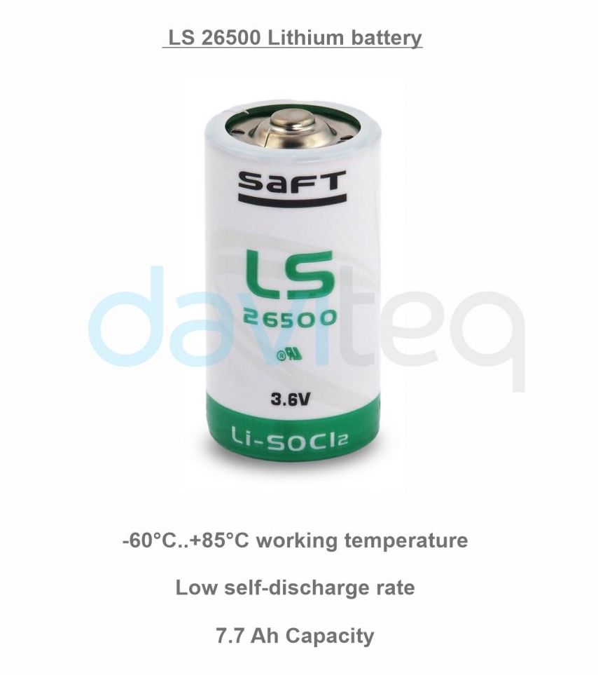
The sensor is powered by 1 x Type C battery 3.6V LiSOCl2 for many years of operation. We do recommend using Saft
LS26500 battery which is suitable for Exd-approved instruments. This battery has a capacity of up to 7700mAh with a
working temperature range from -40 to +85 oC. The instruction for installing the batteries is in this link.
Finish this part so you can understand and put the sensor in operation with the default configuration from the
factory.
1.1 What is the Sigfox-Ready GHC Flammable Gas Sensor and its
principle of operation?
1.1.1 What are the typical applications of this sensor?
1.1.2 When does the device send uplink messages?
To change the cycle of data sending, you can change the value of the parameter: CYCLIC_DATA_PERIOD (default
is 600 seconds).
The alarm thresholds can be changed via downlink or offline tools.
1.1.3 The important configuration parameters
1.1.4 What kind of battery is used for this sensor?
Note: The battery can be inserted into the device in the Safe Zone only!!!

Figure 1. Battery SAFT LS26500
For Battery life estimation, please refer to this link.
Figure 2. Product package of WSSFCEX-GHC-01
With the default configuration, the device can be connected quickly to the Sigfox Network by the following steps.
Device ID
Get Devive ID on the device nameplate
Device PAC
Get Devive PAC on the device nameplate
1.2 What's in the package?
The package includes the following items:
01 x Main device
01 x Magnet key
01 x Antenna Type N connector
1.3 Quick Test
Step 1: Prepare the values of communication settings:
Note: All Sigfox sensors are pre-configured with the correct RC before delivery. The settings of Device ID,
Device PAC, and RC could also be read from the device memory map. Please reference section 3.2 Sensor
configuration for details.

Please refer to this link for details
Please refer to this link for instructions on battery installation.
Please refer to section 1.4 Uplink Payload and Data Decoding for details of decoding the receiving packet to get
the measured values.
For the Uplink Payload structure, please refer to sections B and C in this link.
Figure 3. Dimensions
Please refer to this link.
The Sigfox-Ready GHC flammable gas sensor is a wireless device with an integrated gas sensor to detect combustible
gas.
1.5.3.1 Preparation before installing the device at the site location:
Insert the batteries into the device in Safe Zone;
Step 2: Add the device to Sigfox Backend
Step 3: Install the batteries to the device
After installing the battery in 60 seconds, the first data packet will be sent to the Sigfox network. After receiving
the first data packet, the time of another packet depends on the value of the parameter:
CYCLIC_DATA_PERIOD. Additionally, you can use a Magnet Key to force the device to send data instantly.
Step 4: Decode the payload of receiving package
1.4 Uplink Payload and Data Decoding
1.5 Sensor Installation
1.5.1 Dimension drawings
1.5.2 Device calibration & configuration
If Configuration and Calibration are needed for the device, please perform those tasks in the Safe
zone, before installing the device at the site.
1.5.3 Installation

Make sure the device run and connect to the Sigfox Network successfully;
1.5.3.2 Installing the device at the actual location as below steps:
Locate the place to detect the target gas. Please follow this link;
Make sure the site is good enough for RF signal transmission. Please take notes as in this link;
Mount the sensor onto a wall by two screws as this link;
Problems with Sigfox communication like not receiving the packets...please refer to this link to troubleshoot
the device.
Problems with the sensor functions like not measuring or inaccurate measuring....please refer to this link to
troubleshoot the sensor part.
Maintenance works
Yes/No
Descriptions
Consumable parts replacement
Yes
The battery is the only part need to check the
lifetime to replace. Check the battery status on
the back-end system.
Cleaning device
No
Please refer to this link.
The Daviteq Sigfox-Ready GHC Flammable Gas Sensor comprises 02 parts connected together:
- The Daviteq Sigfox-Ready wireless transmitter
- The Daviteq GHC flammable sensor module
ATTENTION: REVERSED POLARITY OF BATTERIES IN 10 SECONDS CAN DAMAGE THE SENSOR
CIRCUIT!!!
Note: DO NOT OPEN THE DEVICE OR REPLACING BATTERY DURING INSTALLATION AT SITE
(HAZARDOUS AREA ZONE 0, 1, 2)
2. Maintenance
2.1 Troubleshooting
2.2 Device maintenance
2.2.1 Maintenance for Wireless transmitter
2.2.2 Maintenance for GHC sensor module
3. Advanced Guide
3.1 Operating principle of the Sigfox-Ready GHC Flammable Gas
Sensor
3.1.1 Operating principle of the complete device
Table of contents