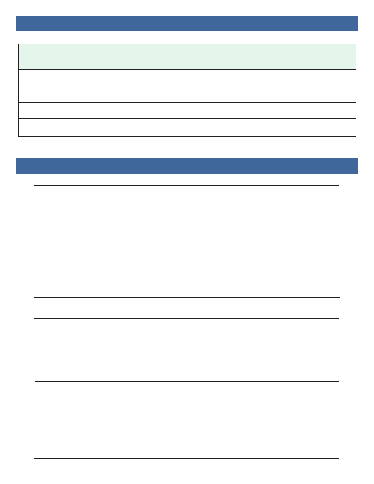
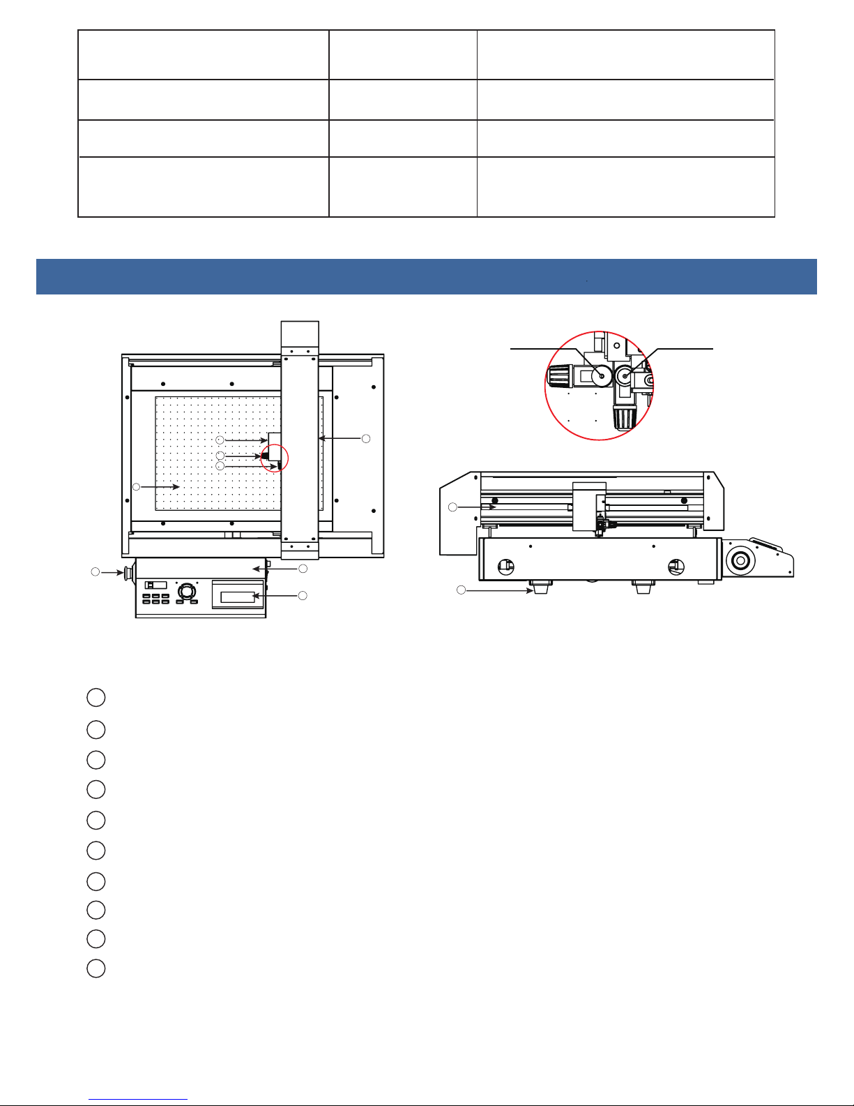
Saga SG-FC4560 User manual

USER’S
GUIDE
CUTTER
FLATBED
SG-FC76106
SG-FCA3+
SG-FC4560
SG-FC6090

1.Introduction of Product
2.Tool Description
3.Operation
4.Software
5.Fault and Maintenance
6.Performance Parameter

CHAPTER
1
Introduction of product
1.1 Type and Specification
1.2 Standard Parts
1.3 Parts Names
1.4 Control Panel

1.1 Type and Specification
Model Effective Cutting
Area
Effective Contour
Cutting Area Stand
SG-FCA3+
SG-FC4560P
SG-FC6090
SG-FC76106
350×510mm
780×1080mm
330×488mm
760×1060mm
450×600mm
600×900mm
470×630mm
620×930mm
No
Yes
No
Yes
1.2 Standard Parts
Qty
Air pump
Hose
Software
Creasing Blade
Blade
Blade Holder
Pen Holder
Circlip Knife
M3 Six
Angle Wrench
M2 Six
Angle Wrench
10A Fuse Wire
USB Cable
Item
Power Cable
1
1
1
1
1
1
3sets
6sets
1
1
1
1
1
Specription
4Shock Pad Footing for stand
(6090/76106 only)
Adjust the height of
the creasing knife
Backup tool
Cutting tool
Cutting tool
Calibration sensor tool
Loading knife
Crease tool
DragonCut
Cutting software
Vacuum suction
Vacuum suction
/
/
/

silence device
Pump Box
1
1
Reduce noise for
air pump
1.3 Parts Names
1
2
3
5
6
7
8
4
9
10
Tool holder 1 Tool holder 2
1Carriage..................Drives the cutter blade/pen/creasing tool to the forward/backward.
2Tool holder 1...........Holds the pen/creasing tool and drives it up/down
3Tool holder 2...........Holds the cutter blade tool and drives it up/down.
4Beam......................Holds the tool carriage ;moves left/right.
5Control panel..........Used to set and use the plotter’s various functions.
6
7
8
Tool Box.................Box for holding tools.
Emergency switch...In case of emergency, turn off the power.
Cutting area............Effective Contour Cutting Area.
9
10
Belt.........................Holds the carriagr to moving.
Shock Pad...............Footing for machine.
1
1
SG-FC76106(only)
Plastic cutting pad
Felt pad
Mainly used for cutting
For creasing effect is better,
(cutting and creasing)

8
1.4 Control Panel
1
234
5 76
9
11
12
13
10
1
LED Display......... Display various parameters.
2Fun1....................The switch for vacuum adsorption function.
3
4
5
6
7
8
9
10
11
12
13
Fun2.................... Return to the main interface, when you set the parameters. Press this key to return to the original interface.
(Original interface display: speed and Force)
Fun3....................The switch for sensor.(the carriage sensor,scan mark)
Reset...................Resrt Key,The carriage will return to the mechanical origin,LED display speed and force.
Set......................Setting machine parameters.
Test.................Runs a cutting test to check whether the currently selected cutting conditions are compatible
with the medium loaded. Usually tool 1 draws a square, and tool 2 cuts a triangle.
Off..................When the speed and Force is displayed, press the off key you can move the carriage and the beam.
Enter...............After setting a function or condition at the control panel, press the [ENTER] key to register your setting.
Power switch..............................Controls the on/off status of the power supply to the cutter.
Air pump jack..............................The jack for connecting main board and air pump
USB interface connector.............Used to connect the cutter to a computer via the USB interface.
SDcard interface connector......... At present this feature is unavailable.
SPEED / FORCE:Control the speed and force of a tool holder 1, generally hold the pen and creasing tool.
SPEED1 / FORCE1:Control the speed and force of a tool holder 2, generally hold the blade.
CAR X/Y :Distance between tool holder 1 and tool holder 2, the offset value of the two tools.
generally do not need to change.
Work Mode:Cut Plotter --Control tool holder 1and tool holder 2 work together.
Draw Plotter--Control tool holder 2 work only.
BaudRate:38400,Computer and motherboard transmission parameters, generally do not need to change.
XP/YP:Scaling X direction and Y direction,generally do not need to change.
Clear Pare:Restore factory settings.
VER:The version for firmware.

CHAPTER
2
2.1 Types of cutter blades
2.2 Blade holder introduction
2.3 replacing the blade
2.4 Adjust the blade length
Tool Description

2.1 Types of cutter blade
Name and pic Angle Applications and
Features
Blade
Blade
diameter
Circlip
Knife
Creasing
Blade
Pen
Holder
60°
45°
30°
60°
45°
0.1mm
0.1mm
0.1mm
0.1mm
0.1mm
/
/
/
/
2.2 Blade holder introduction
Adjustment depth knobs
Lock Pin
Blade
When handling cutter blades, be careful to avoid cutting your fingers or
other parts of your body.
WARNING
≤500gCardboard,
corrugated paper
Calibration sensor
For cutting media which are too
thick for the uitable for cutting media
from 0.25 to 0.5 mm thick
For cutting high-intensity
reflective film.
For thick media. The sharply
angled tip provides a longer
cutting edge. Suitable for cutting
media from 0.5 to 1.5 mm thick.
For cutting sandblast rubber.
For adhesive stickers,
instant paste
For Film ,
very soft material

2.3 Replacing the blade
Step1 Step2 Step3
Step1/Step2/Step3
1. Push the blade to the bottom of the blade holder.
2. Adjust the blade tip to suitable length by rotating “Adjustment depth knobs”
and then tighten the lock.
3. Press the push-pin to remove the blade from the blade holder when replacing blade.
Notice
The blade is a consumable item, and you’ll always get the best quality cut with a newer
blade. Please replace with a new blade when:
1. The tip of blade is broken.
2. The cutting traces are not as good as they were.
3. The blade will not cut cleanly even though the blade force has been raised
significantly.
Do not touch the tip of the blade with your fingers.
WARNING

2.4 Adjust the blade length
The blade length is adjusted by turning the blade adjustment knob.
• To extend the cutter blade, turn the knob in the A direction.
• To retract the cutter blade, turn the knob in the B direction.
How to confirm the right height
Gradually increase the blade length to suit the thickness of the medium being used.
The ideal blade length is a length that is slightly less than the combined thickness of
the film and its backing sheet, but greater than the thickness of the film itself.
Adjust the blade length so that only traces of the blade appear on the backing sheet
when a cutting test is performed. If the blade cuts right through the backing sheet,
decrease the blade length. If the blade does not cut the film cleanly, increase the
blade length.
Cutting surface
Backing sheet
The most suitable length for blade
AB
Be sure to correctly adjust the blade length. If the blade length is too long for the
thickness of the medium being used, you may damage the writing panel and/or
the cutter blade.
WARNING

CHAPTER
3
3.1 Basic Operational Steps
3.2 Connecting to a Computer
3.3 Installing Tools
3.4 Turning on the cutter
3.5 Calibration the sensor
3.6 Loading the Media
3.7 Running a Cutting Test
Operation

3.1 Basic Operational Steps
or
Install software Install stand
(6090/76106only)
Connecting to a Computer
Installling tools
(blade/pen/creasing tool)
Turn on the cutter
Calibration the sensor
Loading the media
Cutting Test
Working

3.2 Connecting to Computer
Only install the software, don’t need to install any driver.
Operation cannot be guaranteed in the following cases:
• When connection has been made to a USB hub or an add-on
USB board
• When you are using a custom-built computer or one that you
have modified
Be sure to observe the following:
• Do not connect or disconnect the USB cable while you are installing
the USB driver
• Do not connect or disconnect the USB cable while starting up the
computer or the plotter
• Do not disconnect the USB cable within a 5-second period of
connecting it
• Do not connect or disconnect the USB cable while data is being
transferred
• Do not connect multiple plotters to a single computer
Use a USB cable or an RS-232C cable in accordance with the
interface chosen.After the connection is successful, the software
will show whether the normal connection.

3.3 Installing Tools
Step1.....Loosen the tool holder screw sufficiently to enable a cutter
pen to be inserted up to its flange.
Step2 Step3
Step2.....Push the cutter pen all the way into the holder until it contacts
the upper part of the tool holder.
Step3..... Tighten screw.
When you push the tool holder up with your fingers,take care not to touch
the cutter blade.
WARNING
3.4 Turning on the cutter
1.Securely plug the other end of the power cord into an electrical outlet of the
specified voltage.
2.Turn on the power.
3.The green power lamp on the control panel will light, and the Y bar and
carriage will start to move as shown in the figure below. These operations
are part of the initialization process.

Beam
carriage
The figure below shows what the
plotter does when the power is
turned on. The tool carriage returns
to the Home position.
3.5 Calibration the sensor
Step1......Put a blank A4 paper on the flatbed.
Step2.....Move the car to the middle of the paper.
Step3.....Install the pen holder in hold2 and select the appropriate pen pressure.
Step4.....Open the software to find the calibration interface
Step5.....Direct calibration, calibration is successful, the interface appears a correct
XY parameters, click ok.

A4 Paper
A4 Paper
Step1 Step2
Step3 Step4
Step5

3.6 Loading the media
3.5 Running a cutting test
Blank cutting
ARMS cutting
Make sure the materical is flat.
Place the paper on the platform and move the carriage to the starting point of the cutting
Place the paper on the platform and move the carriage to the starting point of the mark
Moving the carriage to a blank area (no marks and pictures)
Press “TEST” and then tool 1 draws a square, and tool 2 cuts a triangle.
Installing a pen in tool holder1,installing a blade in tool holder 2.

Tool1 painted a blank box, tool2 painted a red box,
which can test the force of blade/pen/creasing
Cutting medium Blade height Force Speed
Media height
or gram weight
Creasing
Force
Blade
Stickers
Adhesive stickers
Thick paper
Masking rubber
for sandblasting
Magnetic stickers
Reflective film
160g
0.24mm
0.5mm
300g
90g
0.5mm
0.2mm
0.15mm
0.76mm
2.5mm
0.6mm
0.30mm
400g
50g
50g
210g
500g
450g
120g
150mm/s
500mm/s
600mm/s
75mm/s
500mm/s
300mm/s

CHAPTER
4
4.1 Install and activate
4.2 Common parameters of software
4.3 How to use DragonCut
Cutting and Creasing
Software

4.1 Install and activate
Please install CD first and check your 20 bits license.
Please pay attention to a few points as follows
1.Enter your license
(Each license can be
used 3 times only)
2.Pay attention to the your
machine model
SG-FCA3+ choice 720IIP
SG-FC4560 choice 720IIP
SG-FC6090 choice 720IIP
SG-FC76106 choice 1350IIP
This manual suits for next models
3
Table of contents