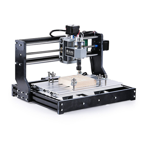
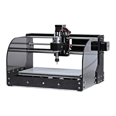
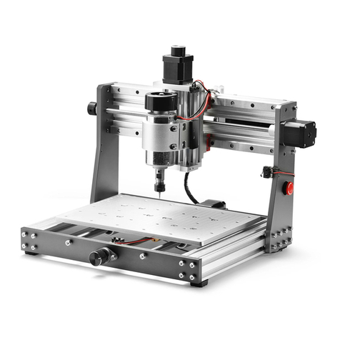
SainSmart Genmitsu PROVerXL 4030 User manual

V1.0 Aug 2020
USER MANUAL
Genmitsu PROVerXL 4030
CNC Router

01
Welcome
Disclaimer
Specifications
Part 1 - Unboxing
Part 2 - Mechanical installation
Part 3 - Wiring
Part 4 - Software Setup
Part 5 - Test Project
Part 6 - Z Probe Setup
02
03
04
05
10
24
29
32
34
........................................................................................................................................
..........................................................................................................................................
...........................................................................................................................
.................................................................................................................................
...................................................................................................
.......................................................................................................................
.................................................................................................................
.................................................................................................................................
...................................................................................................................
Contents

02
Thank you for purchasing the Genmitsu PROVerXL 4030 CNC Router from SainSmart.
Included in your package will be a USB Stick, you will find:
● PDF version of this manual
● Windows USB Driver
● GrblControl/Candle software for Windows
● Sample files
Please visit SainSmart Online Resource Center installing drivers and software for your CNC.
https://docs.sainsmart.com/proverxl-4030
The driver and software can also be found on the included USB stick.
For technical support, please email us at [email protected].
Help and support is also available from our Facebook group.
(SainSmart Genmitsu CNC Users Group)
Welcome
Scan QR code
to join the group

03
Disclaimer
Please be careful when using your CNC machine. This machine is an electrical device with moving parts and
dangerous areas.
● Genmitsu CNC Machines are for Indoor Use Only.
● You must be 18 years or older to operate this machine, unless supervised by a knowledgeable adult familiar with the machine.
● Wear the proper Personal Protection Equipment (Safety Glasses etc.).
● Always place the CNC Machine on a stable surface.
● The SainSmart Genmitsu CNC Machine is supplied with Switchable Power Supply 230 VAC or 115VAC. Never use a different
power supply; it may cause malfunctions or damage to the machine.
● The PROVerXL 4030 utilizes a high amp power supply. It is recommended that you do not plug the CNC Router into an
extension cord, or power strip as it may damage the machine.
● Ensure the Emergency stop button is easily accessible at all times.
● Never disassemble the Power Supply or Electrical Components. This will VOID the warranty.
● DO NOT TOUCH the machine spindle, or place any body part near the working area when the machine is operating. Serious
Injury may occur.
● DO NOT leave children unsupervised with the CNC Machine even when it’s not operating. Injury may occur.
● DO NOT leave the machine unattended while it's operating.
● Ensure your CNC Machine is in a well-ventilated area. Some Materials may discharge smoke or fumes during operation.

04
Specifications
Working Area
Motor
Input Voltage
Input Current
Spindle Speed
Spindle Power
Drive System
MDF Spoilboard Size
Firmware
Emergency Stop Switch
Limit Switch
Speed Control Button
C-Beam®Linear Rail
Machine Weight
Package Weight
Color
Supported OS
Software
Frame Material
400 x 300 x 110mm
NEMA23
115V/230V
8.5A/115V; 4A/230V
12000r/min
DC24V 300W
Leadscrew T10
300 x 400 mm
GRBL 1.1
YES
X, Y, Z
YES
X, Y, Z
26kg
30kg
Blue & Aluminum White
Windows XP, Windows 7 32/64 bits, Windows 8, Windows 10, Linux, Mac OS
Grbl control(Candle)
Aluminum

05
X-Axis & Spindle
Z-Axis Assembly
1
(2) Dust Baffle
5
Y-Axis Base Assembly
2
(4) NEMA 23
Stepper Motor
6
3 4
Spindle Collet
7 8
(4) Stepper
Motor Mount
Drag Chain
Mount
Mechanical Parts List
Please make sure all the following parts are included. If you are missing any part or have any questions, please email us at
Part 1 - Unboxing

06
10 11
9Drag Chain Mount (2) Drag Chain Mount Cable Management
MDF Spoil Board
12
Electrical Parts List
USB Cable A-B
16 17 Power Cable (US)
1.2M
PROVerXL
Control Center
15
Bakelite Sheet
175 x 100 x 5mm
13 MDF Board
175 x 100 x 5mm
14

07
25 User Manual
Tools/Accessories Parts List
Probe
Z-Height Mapping Probe
19
24
(10) Engraving Bit Kit
30 Degree, 0.2mm Cutting area,
3.175 Diameter
20
22 23
18 (4) Material Clamp
21
(10) Nano Blue Coat Bits
3.175mm Shank, Cutting Edge
Diameter: 0.8-3.0mm
(5) Allen Wrench
2.0mm, 2.5mm, 3.0mm,
4.0mm, 5.0mm
Wrench
Nylon Braided Wrap
340mm USB Stick
26
V1.0 Aug 2020
USER MANUAL
Genmitsu CNC Router PROVerXL 4030

08
27 (2) M5 T- Nut 28 29
(4) M5 x 8mm
Socket Cap Screw
(14) M5 x 16mm
Socket Cap Screw
Screws/Other Parts List
31 (8) M5 x 50mm
Socket Cap Screw
35 (3) Coupler 36 37
(10) 5mm
Spring Washer
(10) 5mm
Flat Washer
32 (4) M5 x 55mm
Socket Cap Screw 33 (2) M4 x 6mm
Socket Cap Screw 34 (2) M4 x 8mm
Socket Cap Screw
30 (6) M5 x 20mm
Socket Cap Screw

09
Optional Accessories (Not Included)
Consider following optional upgrades or accessories to make your CNC experience better!
You can find them on www.sainsmart.com.
Save 10% with discount code PROVerXL
Router Bits Holder
Storage Case
CNC Router Bits
Essential Kit
Resin Board for CNC
Engraving, 2-Pack
Acrylic Sheet for CNC,
180 x 100 x 5mm, 4-Pcs
Scan QR codes to learn more

10
Part 2 - Mechanical installation
31 (8) M5 x 50mm
Socket Cap Screw
(2) NEMA 23
Stepper Motor
6
7(2) Stepper
Motor Mount
2.1 Preparing your Base Assembly
What you will need
Y-Axis Base Assembly
2
22 Allen Wrench
35 (2) Coupler

11
Step 1: Inspect your Base Assembly after removing it from the
packaging. Before starting assembly, verify the base is square
by using a 90-degree straight edge, as shipping may have
caused things to shift.
Step 2: Install the flexible coupler onto each Y-Axis leadscrew.
Loosen the small set screw to ensure the Lead Screw will
completely seat inside.
Step 3: Tighten (2) M6 x 16mm screws to secure the lead
screw mount.
Step 4: Next comes the Motor Mounts & Stepper Motor.
Lay the Stepper Mount on your flat surface, positioning it
so the open side will not face down when installed. Place
the NEMA-23 Motor onto the mount aligning the screw holes.
Insert the M5 x 50mm screws.
Step 5: Holding the Mount & Motor together with the screws,
install the assembly to base as shown in the diagram.
35 7631
2

12
2.2 Finishing your Base Assembly
What you will need
MDF Spoil board
12
30 (6) M5 x 20mm
Socket Cap Screw
Y-Axis Base Assembly
2
Step 1: Position the MDF Spoilboard on the PROVerXL 4030
Base and align with the screw holes at the front and back
of the machine. Be sure the board is right side up (Threaded
Inserts should be towards the bottom, if you install it in
reverse the mounting screws will protrude from the top
of the spoil board). Tighten with M5 x 20mm Screws.
Step 2: Align each Dust Baffle to the side of the spoil
board, align with the screw holes and tighten down with
the M5 x 16mm screws.
29 (4) M5 x 16mm
Socket Cap Screw
(2) Dust Baffle
522 Allen Wrench

13
29
5
30
12
2

14
2.3 Preparing your X-Axis Gantry
(2) NEMA 23
Stepper Motor
6
What you will need
32 (4) M5 x 55mm
Socket Cap Screw
X-Axis & Spindle
Z-Axis Assembly
17Stepper Motor Mount
35 Coupler
22 Allen Wrench

15
Step 1: Install the flexible coupler to the X-Axis Leadscrew.
Be sure to loosen the grub screws to ensure the shaft full
seats inside.
Step 2: Just like the Base preparation. Prep your Stepper
Motor Mount + NEMA 23 Motor and 4 socket cap screws
and remember to position the mount with the opening
facing towards the rear of the gantry.
1
735
Step 3: Mount the assembly to the X-Axis. Tighten the
grub screws on the coupler. Manually twist the wheel
on the Stepper Motor to verify smooth movement of the
Gantry on the X-Axis.
32 6

16
2.4 Finishing your X-Axis Gantry
What you will need
28 (2) M5 x 8mm
Socket Cap Screw
X-Axis & Spindle
Z-Axis Assembly
19Drag Chain Mount
Step 1: Position the X-Axis Limiter to the rear of the Spindle Carriage as shown in the diagram. Install the bracket and tighten
the screws.
22 Allen Wrench

17
28
9

18
2.5 Finishing Frame Assembly
What you will need
36 37
(8) 5mm
Spring Washer
(8) 5mm
Flat Washer 29 (8) M5 x 16mm
Socket Cap Screw
Step 1: Position the X-Axis gantry onto the Y-Axis carriage mounts
as shown in the diagram. Each carriage has an acrylic plate that will
hold the gantry at the appropriate height. Install the gantry using a
5mm washer, 5mm spring washer then M5 x 16mm screw as shown
in the diagram.
Step 2: Secure the opposite side to complete the
installation.
Step 3: Rotate both wheels on your Y-Axis stepper
motors to ensure smooth movement of the X-Axis
Gantry along the Y-Axis.
22 Allen Wrench

19
36 37
29
Table of contents
Other SainSmart Control System manuals