SAINT-GOBAIN BarbLock BLT-HHPAD User manual

Saint-Gobain BarbLock®
Assembly Tool
Part Number BLT-HHPAD
OPERATIONS MANUAL
www.biopharm.saint-gobain.com

BarbLock® Assembly Tool: Operations Manual
www.biopharm.saint-gobain.com
2FLS-5278C-CLWR-Rev 01
Table of Contents
Important Notice 3
Tool Identification 4
General Description 4
Warnings and Safety Labels 4
Tool Controls and Features 6
Jaw Installation and Removal 8
Operation of the BarbLock® Assembly Tool 9
Air Supply Connection 11
Operational and Safety Checks 12
Noise Emissions 12
Vibration 12
Tool Balance Connection and Use 12
Residual Risks 13
Use and Storage Conditions 13
Cleaning 13
Maintenance and Service 13
Jaw Size Reference List 14
Rail Greasing Procedure for BarbLock® Assembly Tool 14
Disassembly 15
Greasing the Carriage 16
Reassembly Procedure 17
Functional Confirmation 17
Troubleshooting 18
Tool Physical Details 19
Copy of CE Mark Declaration Of Conformity 20

BarbLock® Tabletop Pneumatic Assembly Tool: Operations Manual
www.biopharm.saint-gobain.com 3
FLS-5278C-CLWR-Rev 01
Read this before using the Saint-Gobain Performance Plastics BarbLock® Assembly Tool
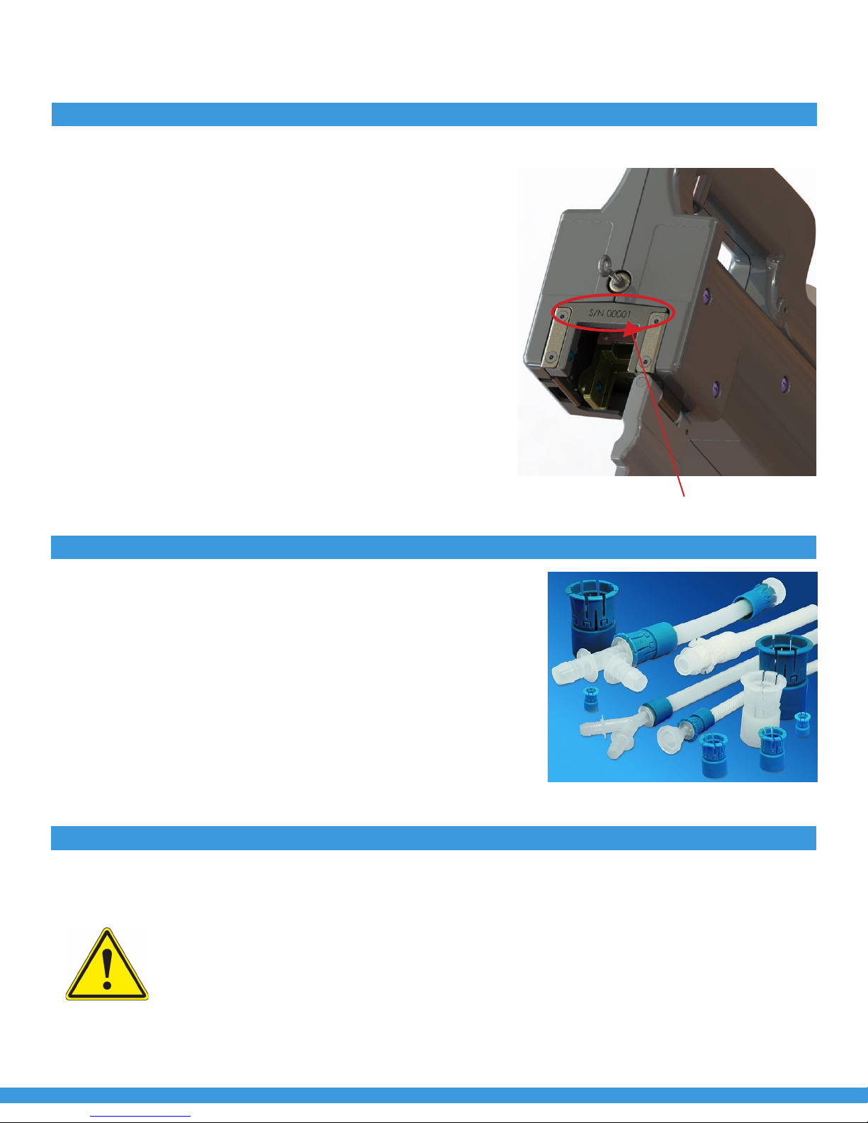
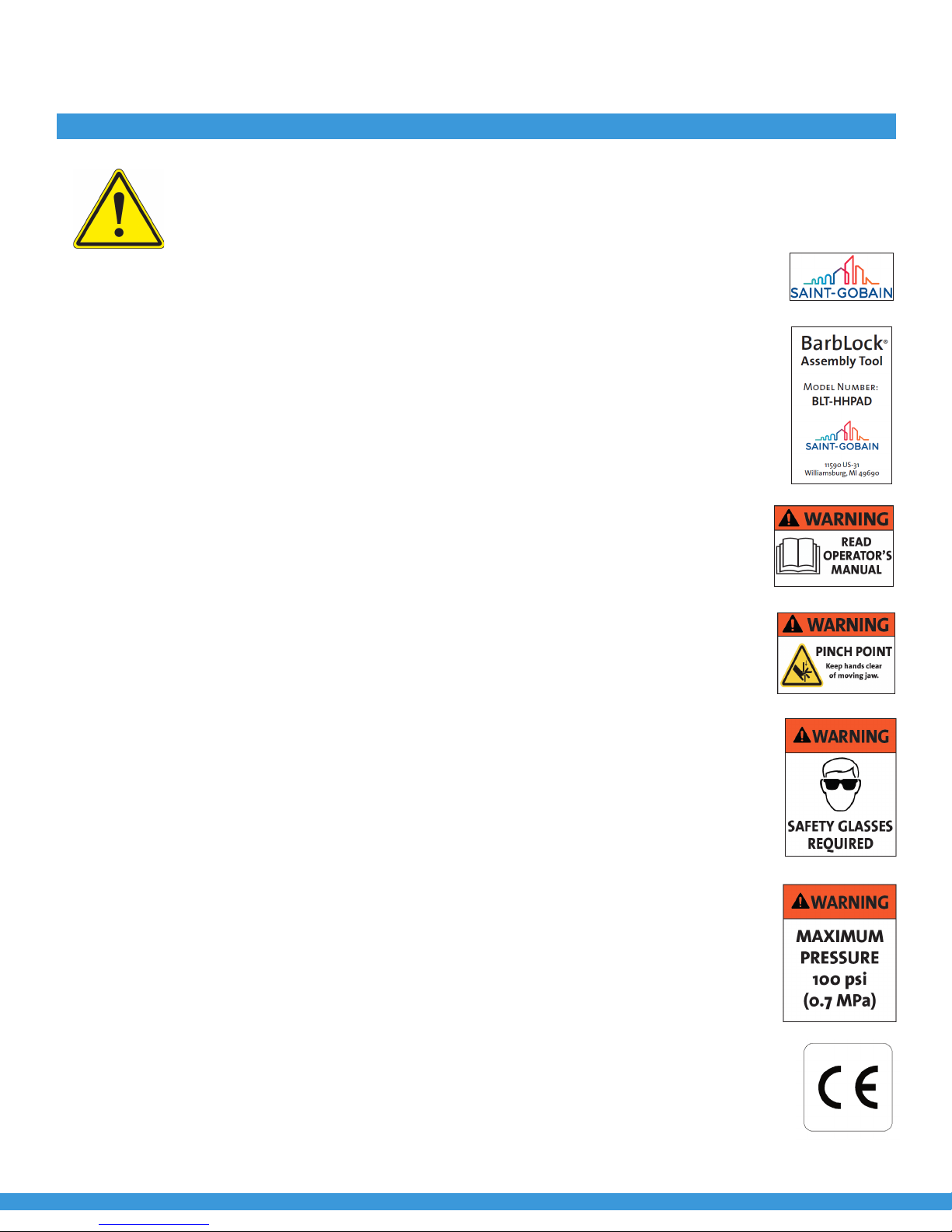
We, as an authorized representative of Saint-Gobain of Williamsburg Michigan, USA certify and declare that the
following BarbLock® Pneumatic Assembly Tool:
All users must read the entire BarbLock® Assembly Tool Operating Instructions before installing, using or main-
taining the tool. Always keep the Operating Instructions at hand when using the BarbLock® Assembly Tool.
IMPORTANT: It is the user’s responsibility to ensure the suitability and safety of Saint-Gobain products for all
intended uses and that the materials to be used comply with all applicable medical regulatory requirements.
Saint-Gobain assumes no responsibility for any product failures that occur due to misuse arising out of the
design, fabrication or application of the products into which the materials are incorporated. Saint-Gobain
cannot assume liability if the BarbLock® Assembly Tool is subjected to improper use or operation. Saint-Gobain
is not liable for any damages resulting therefrom. The operator bears the sole risk. Proper use also includes
compliance with operating, inspection, and maintenance conditions prescribed by the manufacturer. Non-com-
pliance with the warnings in the operating instructions and installation instructions, in particular, constitutes
improper use of the equipment.
There is only one user serviceable parts inside the Tool, described in the section beginning on page 19.
Accessing the inside of the tool for any other reason may void the warranty. Contact Saint-Gobain Performance
Plastics if the product fails to operate correctly. Do not continue to use a product that is not operating correctly,
as this could result in injury to the operator or others, or damage to the product.
Intended Use
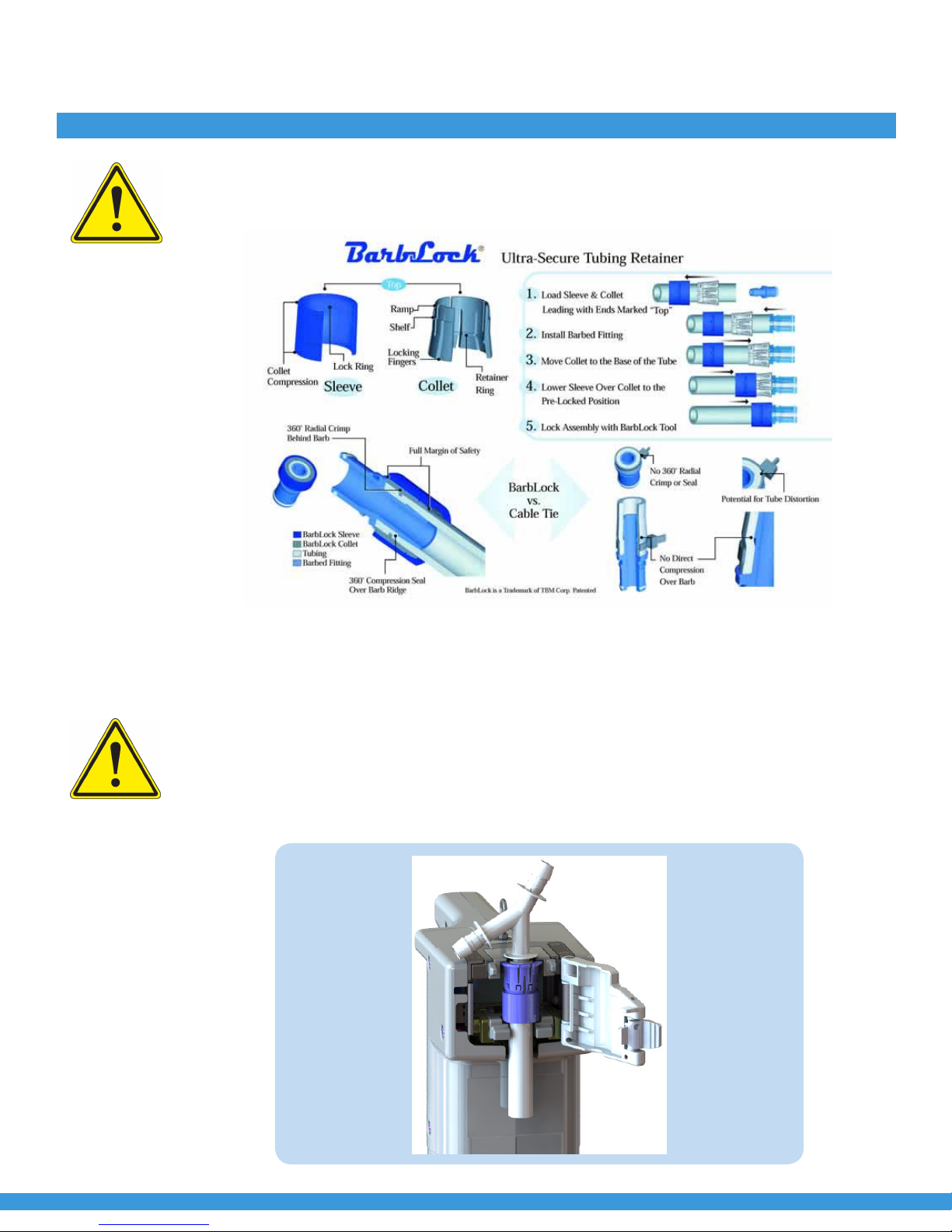
The BarbLock® Assembly Tool was exclusively developed, constructed, and built for the industrial and com-
mercial purpose of closing/locking the BarbLock® and Pure-Fit® SIB® retainers on a barbed fitting and flexible
tubing connection using pneumatic power. The BarbLock® Assembly Tool shall not be used in any clinical proce-
dures, or for diagnostic purposes. The system is exclusively designed for the purpose stated above. Any other
application above or beyond this, or any modifications to the unit without the written permission of the manu-
facturer, is considered as improper use of the device, which could result in injury to the user or damage to the
tool.
1.0 Important Notice

BarbLock® Assembly Tool: Operations Manual
www.biopharm.saint-gobain.com
4FLS-5278C-CLWR-Rev 01
2.0 Tool Identification
BarbLock® Assembly Tool
Model Number BLT-HHPAD
Saint-Gobain Performance Plastics
11590 US-31
Williamsburg, MI 49690
Phone: (888) 387-0067
Website: www.biopharm.saint-gobain.com
3.0 General Description
The Saint-Gobain BarbLock® Assembly Tool is a handheld
portable pneumatic device used to crimp (install) the
BarbLock® onto a barbed fitting and flexible tubing connec-
tion. This creates an ultra-secure connection that is more
resistant to leakage than any other available technology.
Figure 2 below shows some of the Saint-Gobain products
with which the BarbLock® Assembly Tool is used.
4.0 Warnings and Safety Labels
This user documentation contains WARNINGS concerning the safe use of the product.
See Definition below.
Figure 1: Tool serial number location
Figure 2: Representative Barblock® Components
WARNINGS
WARNING indicates a hazardous situation which, if not avoided, could result in serious injury to the user or
bystanders, or damage to the tool. It is important not to proceed until all stated conditions are met and clearly
understood.

BarbLock® Tabletop Pneumatic Assembly Tool: Operations Manual
www.biopharm.saint-gobain.com 5
FLS-5278C-CLWR-Rev 01
4.0 Warnings and Safety Labels Continued
WARNING – Safety Glasses Required: any person who is operating, or is in the immediate vicinity of someone who
is operating, a BarbLock® Assembly Tool shall wear eye protection that meets or exceeds ANSI Z87.1. Due to the
significant forces generated by the BarbLock® Assembly Tool, there is a possibility of personal injury from projectile
material that may come from the tool in the event of a failure of a BarbLock® component.
There are seven (7) adhesive labels attached on the outer case of
the tool. The labels are presented and described in this section.
1. Saint-Gobain brand name and symbol (Figure 3)
2. Product identification and company information (Figure 4)
3. This User/Operator manual contains critical information that
must be understood by the user in order to prevent injury to
the user or damage to the tool. (Figure 5)
4. There are pinch points in the tool that must be understood by
the user in order to avoid injury. (Figure 6)
5. There is potential for projectile injury. Use of protective eyewear
is mandatory to avoid injury. (Figure 7)
6. Pressure limit for the tool air supply is 100 psi (0.7 MPa).
Exceeding this limit may damage the tool which could
lead to poor performance and unsafe operation. (Figure 8)
7. CE mark, indicating the tool has passed rigorous safety and
performance testing. (Figure 9)
Figure 8: Pressure Limits
Figure 3: Logo
Figure 4: Product Identification
Figure 5: User/Operator manual
Figure 6: Pinch Point
Figure 7: Protective Eyewear
Figure 9: CE Mark

BarbLock® Assembly Tool: Operations Manual
www.biopharm.saint-gobain.com
6FLS-5278C-CLWR-Rev 01
5.0 Tool Controls and Features
The information below details the location and function of all operator controls and features of the BarbLock®
Assembly Tool.
WARNING – Pinch Hazard
Trigger (actuation button) – this control will cause the lower jaw of the tool to move toward, and close against, the
upper jaw whenever the tool is connected to an air supply and the Safety Cover is closed. Releasing this control
will cause the lower jaw to return to its original (opened) position. The extending and retracting motions of the
lower jaw pose a pinch risk to fingers. Users must keep fingers away from the jaw area during operation of the tool.
Failure of the pneumatic switch behind the trigger could cause unexpected sudden motion of the lower jaw. Users
should remain alert to this possibility and keep fingers away from the jaw area. If this is observed, the tool should
be disconnected from the air supply and removed from the work area. When the jaws are in the closed position, a
pinch risk is present in gaps just below the lower jaw (see Figure 11). Keep fingers away from this area, since it is a
pinch hazard when the lower jaw returns to its open position.
Safety Cover
Upper and Lower Jaws
Trigger
Figure 10: Safety cover open and jaws in open position.
Safety Cover and Latch – the Safety Cover must be open to load the pre-assembled BarbLock® product into the
jaws. The Safety Cover must be closed during operation of the tool. This is in order to prevent user access to the
jaw area while the BarbLock® is being closed, because of the risk of injury to fingers. The Safety Cover also provides
support to the BarbLock® while it is being crimped in place by the moving jaws. The latch secures the Safety Cover
in the closed position whenever it is engaged. There is an audible snap sound when the Safety Cover closes and the
Latch engages. The Safety Cover engages an interlock switch while it is closed. The interlock prevents movement
of the jaws any time the Safety Cover is not closed.

BarbLock® Tabletop Pneumatic Assembly Tool: Operations Manual
www.biopharm.saint-gobain.com 7
FLS-5278C-CLWR-Rev 01
5.0 Tool Controls and Features Continued
Latch – push on
opposite side to
open Safety Cover
Pinch hazard in
this opening. Keep
fingers out at all
times.
Figure 11: Safety Cover n closed position.
WARNING – Pinch Hazard
If the Safety Cover is closed and there is no product in the tool, there is risk of injury to any fingers inserted into the
openings that are normally occupied by the tubing and connector. The tool is not able to distinguish the absence of
BarbLock® components, so the jaws will move any time the Safety Cover is closed and the trigger is pressed. Keep
fingers away from all openings in the area of the jaws. Failure to do so could result in a serious pinching injury to
the fingers.
Jaws – each jaw pair is designed to fit specific BarbLock® part numbers. Refer to the reference list of jaw sizes at
the end of this document. Each jaw is marked with its part number. Jaws are to be used as a matched set, meaning
the same part number for the upper and lower jaws. There is an “A” sux in the upper jaw part number and a “B”
sux in the lower jaw part number. Mismatch of jaws is very likely to result in failure to close the BarbLock® and/or
damage to the BarbLock®.
Figure 12: Jaws
Push here for jaw
removal. Ensure that
air supply is discon-
nected during jaw
removal or installation.

BarbLock® Assembly Tool: Operations Manual
www.biopharm.saint-gobain.com
8FLS-5278C-CLWR-Rev 01
6.0 Jaw Installation and Removal
WARNING – Pinch Hazard
Jaw Installation and Removal - disconnect the air supply before installing or removing the jaws. Failure to discon-
nect the air supply could result in unexpected closing of the jaws which could cause pinching injuries to fingers.
It could also cause damage to the Assembly Tool. The user is to make certain that the jaws are fully seated in their
respective carriers before re-attaching the air supply and actuating the Assembly Tool by depressing the trigger.
Lower Jaw with “B”
part number sux
Figure 13: Lower Jaw in rotated position, for entry or removaL from Lower Jaw Carrier.
Upper Jaw not present in this image.
Jaw tail
Figure 14: Example of Upper Jaw, showing part number with sux letter “A” to indicate upper position.
Jaws are installed in their respective carriers (“A” sux on the Jaw part number for the upper position, and “B” suf-
fix on the Jaw part number for the lower position) by approaching the carrier with the “tail” of the jaw leading the
approach and with the jaw at an angle of roughly 30° (see figure 13). After the “tail” has entered the locking slot in
the carrier, the jaw is rotated into the carrier seat (parallel with carrier). The jaw will snap into place when it is
correctly loaded. It is not possible to load the jaw backwards, nor is it possible to put the jaw into the wrong carrier.
Snapping the jaw into place requires only moderate force exerted by the fingers. Removal of the jaws begins with
pushing on the two “ears” to disengage the detent (figure 12). The jaw is then rotated and lifted out of the carrier.

BarbLock® Tabletop Pneumatic Assembly Tool: Operations Manual
www.biopharm.saint-gobain.com 9
FLS-5278C-CLWR-Rev 01
Assembled jaws are retained in their respective Carriers by a pair of ball-detent devices. Jaws are removed one at a
time by pushing with fingers or thumbs (as indicated by the red arrows in Figure 12) to release the detent mecha-
nism. Each jaw will rotate toward the other and then can be lifted out of the tool. They are installed by reversing the
removal operations. Do not use force or tools to install or remove them. Doing so could damage the BarbLock®
Assembly Tool. If the jaws do not install easily, then it is very likely they are not in the correct position or orientation.
Figure 15: Upper and Lower Jaw Carriers. Jaws are not present in this image.
6.0 Jaw Installation and Removal Continued
Jaws not present
7.0 Operation of the Barblock® Assembly Tool
WARNING – Pinch Hazard: be aware that if the lower jaw carrier has been manually pushed away from its fully
open position while the air supply is disconnected, it will immediately return to the fully open position as soon as
air pressure is re-applied to the tool. This will happen no matter if the Safety Cover is closed or not! Be aware of the
possibility that the lower jaw/carrier may move while connecting the tool to the pressurized air supply. Keep fingers
and hands away from the area of the jaws and carriers while the air supply is being connected.
Operation of the BarbLock® Assembly Tool: The tool is designed to be used by a single operator. To begin the
BarbLock® assembly sequence, the operator will pre-assemble the BarbLock® components onto the tubing. Refer
to the diagram below for general information. Isopropyl alcohol is allowable as a lubricating agent for the pre-as-
sembly operation only. The pre-assembly is then installed into the jaws of the Assembly Tool. Do not apply any
fluid to the BarbLock® components after they have been loaded into the tool. The fluid could contaminate sensitive
components and shorten life of the Assembly Tool. This manual is provided as a guide for operation of the Bar-
bLock® Assembly Tool. Contact Saint-Gobain Performance Plastics if additional information regarding pre-assembly
of BarbLock® components is needed. Figure 16 below illustrates a pre-assembled BarbLock® loaded into the jaws
of the Tool. Note that the flange of the barbed fitting is above the “rim” of the upper jaw. The Safety Cover is then
closed and latched.

BarbLock® Assembly Tool: Operations Manual
www.biopharm.saint-gobain.com
10 FLS-5278C-CLWR-Rev 01
WARNING – Pinch Hazard: do not leave hands or fingers in close proximity to the Safety Cover, the Latch, or the
BarbLock® components that are loaded into the tool. Leaving fingers in close proximity to the moving parts of the
Assembly Tool could result in pinching injury to fingers.
Figure 16: BarbLock® Assembly
The operator grips the tool handle with either the right or left hand, with the index finger in proximity to the Trig-
ger. The operator then pushes and holds the Trigger - the Assembly Tool will drive the BarbLock® components to a
fully closed and locked position. There is no need for the operator to provide intervention to the BarbLock® assembly.
WARNING – Pinch Hazard: after the BarbLock® has fully closed, the operator can release the Trigger. This will cause
the jaws to retract to the full open position. Do not place fingers or hands near the Safety Cover, Latch or the
BarbLock® components until after the jaws have returned to the fully open/retracted position. Failure to keep hands
and fingers away from the working area of the tool while the jaws are retracting could result in a pinch injury. Once
the jaws have returned to the fully open/retracted position, the operator will then apply light force to the back side
of the Latch to open the Safety Cover. The completed BarbLock® assembly can then be removed from the tool.
8.0 Operation of the Barblock® Assembly Tool
Figure 17: Pre-assembled BarbLock® loaded in Tool. Safety Cover in open position.

BarbLock® Tabletop Pneumatic Assembly Tool: Operations Manual
www.biopharm.saint-gobain.com 11
FLS-5278C-CLWR-Rev 01
9.0 Air Supply Connection
The BarbLock® Assembly Tool is powered by compressed air that enters the tool through a 1/4” female NPT fitting
behind the handle. The air supply is to be clean and dry, without lubrication, in order to prevent contamination of
the BarbLock® products being assembled by the Tool. The maximum allowable and optimal supply pressure is
100 psi (0.7 MPa). Exceeding the air pressure limit can damage components inside the tool. Damage to internal
components could lead to unpredictable operation, such as “drift” of the jaws toward the closed position. If this is
observed, then immediately discontinue use of the tool, remove it from the work area and contact Saint-Gobain
Performance Plastics Customer Service. Reduced air pressure may be used for smaller sizes of BarbLocks®, as long
as full closure of the BarbLocks® is consistently achieved. Pressure should be adjusted as needed to achieve full
closure of the BarbLocks® in use at the time.
The User/Owner of this tool is to select their own appropriate air fitting to adapt the tool to their air supply system.
Torque input to the 1/4” NPT fitting is not allowed at any time. Torque applied to any item being connected to the
tool must be reacted (backed up) by a wrench placed on the 11/16” external hex of the 1/4” NPT fitting. Failure to
properly react this torque can damage the plastic casing of the tool and possibly other internal components. This
warning applies to installation and to removal of any item that is attached to the tool’s 1/4” NPT air input fitting.
Minimum recommended inside diameter for the air hose is 3/8” (9.5mm). Smaller hose sizes may not perform well
with some of the larger BarbLocks® due to restriction of the air supply.
Figure 18: BarbLock® Assembly Tool
Compressed Air Connection
(Installed)
Tool Balance
Connection
Jaw set with
upper and
lower pieces

BarbLock® Assembly Tool: Operations Manual
www.biopharm.saint-gobain.com
12 FLS-5278C-CLWR-Rev 01
10.0 Operational and Safety Checks
Depressing the Trigger will not cause movement of any part of the BarbLock® Assembly Tool unless the Safety Cover
is closed and engaged with its interlock switch.
WARNING – Pinch Hazard: be aware that failure of the Safety Cover interlock switch could allow an exception to
this. If the interlock switch fails, the jaws could move while the Safety Cover is open. Keep fingers clear of the
jaws in order to avoid pinch injuries.
WARNING –Read This! The Safety Cover interlock switch should be tested at the start of each work shift. Open the
Safety Cover and pull the Trigger, while keeping fingers away from the area of the jaws. The jaws should not move.
If the jaws move, this is an indication of a failure of the interlock switch or other component in the tool’s pneumat-
ic circuit. Discontinue use of the tool, disconnect the air supply and remove the tool from the work area. Contact
Saint-Gobain Customer Service for assistance.
With the Safety Cover closed, depressing the Trigger will close the jaws. Releasing the Trigger will immediately
cause the jaws to return to the fully open position.
If the Safety Cover is closed and the Trigger is depressed (causing the jaws to close), then opening of the Safety
Cover will cause the jaws to immediately return to the fully open position.
IMPORTANT – Read This! Do not attempt to defeat the Safety Cover interlock switch. The switch is there to protect
the user from injury that may occur from unexpected motion/closing of the jaws. The interlock switch reduces the
opportunity for pinch injuries by preventing motion of the jaws any time the Safety Cover is open. If the Safety Cover
interlock switch is defeated, then the jaws can move while the Safety Cover is open and a pinch injury becomes
more likely.
11.0 Noise Emissions
Low level noise is emitted by the tool during operation. The noise is generated by the release of pressurized air from
the air cylinder any time the Trigger is pressed or released. The air is released internal to the Tool, which significantly
mues the noise level so that it does not pose any risk of hearing injury. This low sound level does not require any
type of hearing protection or exposure duration limitation.
12.0 Vibration
There is no vibration noticeable to the operator during use of the tool. There is no need for exposure limitation or
vibration mitigation measures.
13.0 Tool Balance - Connection and Use
The BarbLock® Assembly Tool has been provided with a connection for a tool balance. Refer to figure 18. This can
be used to oset most of the weight of the tool to reduce operator fatigue, and to reduce the risk of damage to the
Tool in the event that it is accidentally dropped. Weight of the Assembly Tool is approximately 5.4 pounds, with jaws
installed.
IMPORTANT – Read This! The tool balance connection is threaded into the sheet metal chassis of the Tool. It is pos-
sible for the connection to become loose over time and with use. For that reason, it should be checked on a daily
basis or at the beginning of each work shift. If it is found to be loose, disconnect the balance from the Tool, and
then tighten the hex nut against the face of the tool with a 5/16” open end wrench while preventing the eye from
rotating. Thread locking compound may be applied to the threads of the screw eye at the discretion of the Tool
owner. Contact Saint-Gobain Customer Service if this action does not resolve the condition of the tool balance.

BarbLock® Tabletop Pneumatic Assembly Tool: Operations Manual
www.biopharm.saint-gobain.com 13
FLS-5278C-CLWR-Rev 01
14.0 Residual Risks
The risk of injury from compressed air, or from the air hose is always present with devices powered by
compressed air.
- Air under pressure can cause severe injury:
- Always shut o air supply, drain hose of air pressure and disconnect tool from air supply when not in use,
before changing accessories or when making repairs.
- Never direct air toward a person or yourself.
- Whipping hoses can cause severe injury. Always check for damaged or loose hoses and fitting.
- Use caution when using this device.
- Make sure the area is free of hazards, including trip hazards (from air lines in particular)
- Be aware of slippery surfaces caused by the use of IPA with the tool.
- Proceed with care in unfamiliar surroundings. There can be hidden hazards, FLS-5278C-CLWR Page 18 of 27
such as electrical and utility lines.
- This assembly tool is not intended for use in potentially explosive atmospheres.
- This assembly tool is not insulated against contact with electrical power.
All known risks to the operator have been presented and discussed in other parts of this document. There are no
additional risks to be presented.
15.0 Use and Storage Conditions
The following environmental limits are applicable to the BarbLock Assembly Tool.
Use Conditions Storage / Transport Conditions
Temperature (°C) 0 to 40 -10 to +50
Altitude 0 to 6560’ (2000m) 0 to 40,000’ (12.200m)
Relative Humidity (%) 0 to 80 0 to 80
Supply Air Pressure 100 psi (0.7MPa) max. & optimal Not applicable
16.0 Cleaning
The Saint-Gobain BarbLock® Assembly Tool should only be cleaned with isopropyl alcohol on a clean cloth. Do
not apply the isopropyl alcohol directly to the tool – apply the alcohol to a cloth and use the cloth to apply the
alcohol to the tool. Wipe down all external surfaces as needed. The Safety Cover may also be opened and wiped
on its internal faces. The jaws may be removed to allow access to the jaw carriers, which may be wiped down
also. Do not ever apply alcohol directly into the jaw and jaw carrier area, as this may damage sensitive internal
parts. If the jaws are to be cleaned, remove them first.
17.0 Maintenance and Service
Greasing of the linear guide rail and carriage is the only user service operation recommended by Saint-Gobain.
The procedure is described in the section titled Rail Greasing Procedure for Saint-Gobain BarbLock® Assembly
Tool beginning on page 20 of this document.
There are no other user-serviceable parts in the Tool. The internal air cylinder was lubricated for life at the time
of manufacture. It should not require further lubrication. In the event that air cylinder lubrication does become
necessary, contact Customer Service at Saint-Gobain Performance Plastics.

BarbLock® Assembly Tool: Operations Manual
www.biopharm.saint-gobain.com
14 FLS-5278C-CLWR-Rev 01
18.0 Jaw Size Reference List
The following list provides the part numbers of BarbLocks® that are compatible with the corresponding Jaw set part
numbers. Contact Saint-Gobain if additional reference information is needed for an application that has not been
identified in this chart.
BarbLock® Part Number Jaw Set Part Number
PF135125PPAF-AL BLTJAW001
BL135186AL BLTJAW001
BL135187 BLTJAW001
BL135187AL BLTJAW001
PF135187PPAF-AL BLTJAW002
PF135250PPAF BLTJAW003
BL135250 BLTJAW002
BL135250AL BLTJAW002
BL135251 BLTJAW004
BL135253ALHCPVDF BLTJAW003
BL135254ALLRRPVDF BLTJAW002
BL135251AL BLTJAW002
BL135252 BLTJAW005
BL135252AL BLTJAW005
PF135312PPAF-AL BLTJAW006
BL135374 BLTJAW007
PF135375PPAF BLTJAW007
BL135375 BLTJAW007
BL135375AL BLTJAW007
BL135376 BLTJAW007
BL135377ALLRRPVDF BLTJAW007
BL135500 BLTJAW008
BL135500AL BLTJAW008
PF135500PPAF BLTJAW008
BL135501 BLTJAW008
BL135501AL BLTJAW008
BL135503PVDF BLTJAW008
BL135506ALLRRPVDF BLTJAW008
19.0 Rail Greasing Procedure for BarbLock® Assembly Tool
Saint-Gobain Performance Plastics recommends re-greasing of the internal linear guide rail and carriage on an
annual basis. This maintenance requires use of a greasing kit (defined below) and opening of the tool to allow
access to the grease fitting on the Carriage as shown in the images below.
Read and fully understand this entire procedure before attempting to perform this work. There is low risk of
damage to the tool. If damage does occur, it could necessitate action from Customer Service at Saint-Gobain
Performance Plastics.

BarbLock® Tabletop Pneumatic Assembly Tool: Operations Manual
www.biopharm.saint-gobain.com 15
FLS-5278C-CLWR-Rev 01
20.0 Disassembly
Disconnect the air supply before performing any work on the tool. Lay the tool flat on the left side (see image 19 be-
low). Use a Phillips screwdriver to remove the 8 screws that are visible in the right side Case. Lift the right side Case
o the tool, along with its screws. Figure 19 shows the appearance of the tool after removal of the right side Case.
Do not insert any hard or sharp tools or other objects into the interior spaces of the BarbLock® Assembly Tool. Doing
so could damage internal components and cause the tool to malfunction.
Figure 19: Inside of the tool after removal of the right side Case and screws
Figure 20: A close up of view of the grease fitting on end of Carriage

BarbLock® Assembly Tool: Operations Manual
www.biopharm.saint-gobain.com
16 FLS-5278C-CLWR-Rev 01
21.0 Greasing the Carriage
Use THK type AFB-LF grease. Do not substitute a dierent grease. There may be compatibility issues with dif-
ferent greases. Mixing incompatible grease types can damage the tool and cause premature failure of the linear
bearing system. The correct grease, and a grease gun for dispensing the correct 0.6cc volume, can be purchased
from:
Mechatronic Techniques, Inc.
720 F Avenue, Suite 109
Plano, Texas 75074
(214) 431-5727
www.mechatronictechniques.com
IMPORTANT – Read This! The AFB-LF grease can cause serious eye damage or irritation. Eye and face protection is
to be worn when performing the greasing service. THK provides an online MSDS for the grease at this URL:
http://www.thkstore.com/media/msd/AFB-LF_SDS_USA.pdf The MSDS is to be reviewed before performing the
greasing service to the tool.
Figure 21: Greasing kit, THK part number MG70
The two items required to perform the greasing service are the THK MG70 Grease Gun and a 70 gram tube of
AFB-LF grease. The grease is included as a part of the MG70 kit.
The kit also contains several grease nozzles / adaptors. Use the “type L” fitting supplied with the kit (see figure
22 below). Grease is injected into the carriage by inserting the tip of the type L fitting into the open end of the
nipple on the end of the carriage, shown in the red circle in figure 20. Inject only the 0.6cc of grease that is dis-
pensed by a single pump from the grease gun. Grease injection is most eective after removing air from
the grease gun system. Apply moderate force to the back end of the grease cartridge using a blunt object such
as a dowel rod, while moving the grease gun lever through several cycles. The first several strokes of the grease
gun lever will cause a mix of air and grease to be ejected. Continue until there is very little or no air ejected with
the grease. Then insert the tip of the type L grease nozzle into the hole in the end of the fitting on the carriage.
Use a finger to apply force to the type L fitting to maintain engagement with the fitting on the carriage. Inject
just one stroke of grease. Application of excess grease can lead to internal problems with the carriage.
After injecting the new grease, wipe excess grease from the outside of the carriage, rail and grease nipple. Use
a clean soft cloth for cleanup of excess grease. A paper towel is not suitable for cleanup of grease. It is import-
ant to prevent the introduction of dirt and foreign debris into the linear bearing system, since that could cause
increased wear or damage and premature failure.

BarbLock® Tabletop Pneumatic Assembly Tool: Operations Manual
www.biopharm.saint-gobain.com 17
FLS-5278C-CLWR-Rev 01
21.0 Greasing the Carriage Continued
Figure 22: Type L grease fitting, supplied with THK MG70 grease kit.
22.0 Reassembly Procedure
Reassembly is done in exactly the reverse of the disassembly procedure. The small diameter pneumatic tubing
may require slight position adjustment to prevent pinching during attachment of the right side Case. Careful-
ly observe the tubing to see if it is pinched or trapped between parts while the right side Case is re-installed.
Tubing can be damaged (cut or torn) if it is pinched during reassembly. The tool will not operate properly if the
tubing is pinched or cut during reassembly.
Place the right side Case into position on the assembly. It should engage easily with the left side Case, without
any need to force the parts into position. Before installing screws, observe the joint between the left and right
side Cases to confirm that they are properly aligned with each other and the two Case halves are in contact.
Once this is confirmed, insert the 8 screws that attach the right side Case and seat them to a very light snug
condition. Once more, confirm the position of the right side Case by looking for a uniform joint between the two
Case halves. Once this in confirmed, snug the eight (8) screws to complete the reassembly process. Be careful
not to over-tighten.
23.0 Functional Confirmation
The air supply should still be disconnected at this point. If jaws are installed in the tool, ensure they are both
fully seated in their respective carriers. Jaws are not required for this functional confirmation, so they may be
removed if desired.
With the air supply still disconnected, open and close the Safety Cover and latch to confirm proper motion for
both. Be observant for binding or for failure of the Safety Cover to fully close. Test that the Latch engages and
locks the Safety Cover in the closed position.
Confirm that the air supply does not exceed the maximum allowed value of 100 psi.

BarbLock® Assembly Tool: Operations Manual
www.biopharm.saint-gobain.com
18 FLS-5278C-CLWR-Rev 01
23.0 Functional Confirmation Continued
IMPORTANT – Pinch Hazard: attach the air supply to the tool while keeping fingers out of the jaw area – the lower
jaw could move unexpectedly. With the Safety Cover open, depress the trigger. The jaws should not move. If the
jaws do not move, then proceed to the next step in the procedure. If the jaws move, then there is a problem that
must be investigated. Detach the air supply and proceed to the Troubleshooting paragraph below.
Close the Safety Cover, engage the Latch and depress the trigger. The lower jaw should move all the way to contact
with the upper jaw and remain in that position until the trigger is released. When the trigger is released, the lower
jaw should move away from the upper jaw and return to the fully open position. If the lower jaw did not move
as described, then disconnect the air supply and proceed to the Troubleshooting paragraph.
It is desirable, but not mandatory, that the tool should be checked for internal air leaks. If possible, remove the tool
to a quiet area. With the air supply connected, listen carefully for the sound of leaking air, from all around the tool.
If the sound of leaking air is detected, there may be damage to one of the pneumatic tubes. Disconnect the air
supply and proceed to the troubleshooting paragraph.
If the jaws behaved as they should, and no air leaks are detected, then the tool is ready to return to service.
24.0 Troubleshooting
If the Safety Cover, the Latch, or the jaws did not function as they should, as described in the Functional Confir-
mation section, or if an air leak was detected, then something may have been damaged during the re-assembly.
Remove the right side Case again, as described in the disassembly paragraph of this procedure.
Carefully look for any place the small diameter pneumatic tubing could have been cut or pinched. Pinching is
dicult to diagnose if it does not leave permanent damage, since the pinch condition is often removed as soon
as the Case is removed from the tool.
Review the location and path of the tubing and check especially in places where parts come together, since
those are places where the tubing is most likely to be damaged or pinched. Lower the right side Case onto the
tool, watching carefully for places where the tubing may be damaged or pinched. Carefully align and mate the
two side Cases together. Once alignment is confirmed, insert the screws and tighten them snuggly.
Return to the Functional Confirmation paragraph and repeat the checks detailed there. If the tool still does not pass
the tests, then it will be necessary to contact Saint-Gobain Customer Service for repair of the tool.
Warning – Safety Hazard: do not continue to use a BarbLock® Assembly Tool that is not operating correctly. To
do so could result in injury to the operator, to others nearby, or damage to the tool. Disconnect the air supply and
remove any improperly operating tool from the work area. Contact Customer Service at Saint-Gobain Performance
Plastics for assistance with any BarbLock® Assembly Tool that is not functioning properly.

BarbLock® Tabletop Pneumatic Assembly Tool: Operations Manual
www.biopharm.saint-gobain.com 19
FLS-5278C-CLWR-Rev 01
25.0 Tool Physical Details
Tool Weight: 5.2 pounds, including one set of jaws
Tool Dimensions: refer to image below
Figure 23: A schematic of BarbLock® Assembly Tool

BarbLock® Assembly Tool: Operations Manual
www.biopharm.saint-gobain.com
20 FLS-5278C-CLWR-Rev 01
26.0 CE Mark Declaration Of Conformity
Table of contents
Popular Tools manuals by other brands

Dexter Power
Dexter Power PC1300RT Original instructions

WolfPack
WolfPack 07021565 instruction manual

base engineering
base engineering MEC EXCELA-WYND ME9000LH-17 Installation and operating instructions

Darex
Darex XT-3000 operating instructions

Rehau
Rehau RAUTOOL XPAND QC Operating instructions / Technical information

Costway
Costway TL35302 user manual