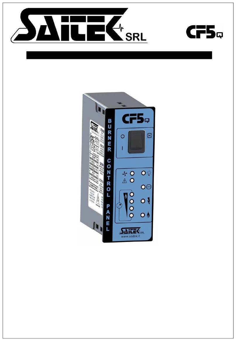
Saitek CF5 Series User manual

Serie
< Automatic burner control unit >
MONO – DOUBLE ELECTRODE / UV-SENSOR FLAME DETECTION
SAITEK srl
www.saitek.it [email protected]
Casalgrande (RE) ITALY Tel . +39 0522 848211 Fax +39 0522 849070


This document is property of Saitek Srl. Copying it and/or spreading the contents to third parties without authorization is forbidden.
Saitek Srl reserves the right to modify the present document at any moment without prior notice.
AUTOMATIC BURNER CONTROL UNIT
C F
5SERIES
MONO – DOUBLE ELECTRODE FLAME DETECTION
IN ACCORDANCE WITH STANDARD EN 298
NOTES .

This document is property of Saitek Srl. Copying it and/or spreading the contents to third parties without authorization is forbidden.
Saitek Srl reserves the right to modify the present document at any moment without prior notice.04-2018
BURNER FLAME CONTROL
C F
5SERIES
page 1 di 5
DOUBLE / SINGLE ELECTRODE FLAME DETECTION
IN ACCORDANCE WITH STANDARD EN 298
INSTRUCTIONS FOR USE .
Read carefully and preserve this use and
maintenance reference manual.
CONFORMIT .
The manufacturer declares that:
- The CF5has been designed, realized
and tested in compliance with the
European Rule EN298 relative to
“Control and safety automatic systems
for gas burners and gas appliances
with or without fan.
- The CF5is conform to the essential
requirements provided for by
Directive 90/396/EEC for gas
applications (E.D. 90/396/EEC art. 1
paragraph 2).
Classification according to EN 298:
B M R L X N
APPLICATIONS .
The CF5flame control appliance directly
lights and controls intermittent gas
burners, or rather burners that shall be
turned off at least once in the 24 hours.
The burner is checked by an ionization
electrode.
For grounded grids.
With a single restart due to flame put out.
The CF5can be applied directly to the
burner in industrial thermal processes for
metals, glass, ceramic, plastic, chemical,
etc...., where there is no need of a pre-
ventilation before turning it on.
Besides it can be applied on atmospheric
burners for general heating.
ATTENTION
Avoid presence of condensation inside
the box and on the card surface..
TECHNICAL SPECIFICATIONS .
- Data relating to power supply
characteristics (V ~ / Hz / W), working
temperature (° C), IP protection class,
discharge time (Ig T), safety (Sc) and
detection threshold ( Sens.), See the
applied label.
- Voltage supplied to the loads the
same to the supply voltage.
- Detection with 2 electrodes, 1
electrode or UV lamp
- Possibility of using both electronic
and traditional ignition transformers.
- LED display: on, block, discharge and
detection.
- Alarm contact in exchange: closed
when in block, closed when in flame
detection.
ATTENTION!!!
Any indication and operation
indicated in the present manual
shall be carried out only by
authorized and qualified personnel
in charge.
Improper and in
correct assembly,
adjustment, modification, use or
maintenance can cause serious
damages and accidents to persons
and things.
Read carefully the instructions
before installing the appliance. The
assembly shall be in compliance
with the regulations in force.
In order to prevent accidental
electrocutions it is recommended
you disconnect the electric current
before opening the appliance.
Before supplying power check the
value reported on the tag.

This document is property of Saitek Srl. Copying it and/or spreading the contents to third parties without authorization is forbidden.
Saitek Srl reserves the right to modify the present document at any moment without prior notice.04-2018
BURNER FLAME CONTROL
C F
5SERIES
page 2 di 5
DOUBLE / SINGLE ELECTRODE FLAME DETECTION
IN ACCORDANCE WITH STANDARD EN 298
SCHEDA VISUALIZZATRICE .
The CF5 flame control is supplied
together with the additional display card
STK035. This offers the opportunity to
control the functionality of the equipment
in a more effective and immediate way.
This is made possible by the four LEDs for
displaying the flame level, the LED for
controlling the safety systems and the
LED for remote unlocking. The latter also
remains slightly lit when the main switch is
in position 0 to indicate presence of
voltage (N.B. can only be used by
authorized personnel keeping under
control the burner to be turned on).
MONTAGGIO .
-Mounting position as desired
-Assembly of the fixed rear part,
through 4 preformed holes to be
removed by pressure.
- Prepared for pipe connection collars
- CF5 can be supplied already wired,
otherwise make the necessary holes
only in the rear part and use cable
glands that guarantee at least the
same degree of IP protection declared.
CAVI CONSIGLIATI .
IONIZATION: Maximum length 10 meters with
recommended section 1 mm. Laying away from
sources of disturbance, avoid external electrical
influences.
IGNITION: as specified by the manufacturer of the
ignition transformer. Recommended conductor
diameter 1mm. Lay individually away from metal
parts.
CABLAGGIO .
Remove power from the system.
In three-phase systems, use the same phase on
the inputs. There must be no voltage present in the
output for the solenoid valve.
The enabling command of the CF5 that comes
from the safety sequence (all the main control
devices for safety purposes such as thermostats,
GASmin, GASmax, leakage control, prewash, etc.
...) must be voltage-free contacts.
The output voltage for the solenoid valve and the
ignition transformer (included if required) is the
same as the supply voltage.
The current max. for solenoid valve and ignition
transformer is 1A.
Alarm contacts max 1A 230Vac not protected by
internal fuse.
Make a good connection of the ground of CF5 to
the burner mass to ensure correct operation.

This document is property of Saitek Srl. Copying it and/or spreading the contents to third parties without authorization is forbidden.
Saitek Srl reserves the right to modify the present document at any moment without prior notice.04-2018
BURNER FLAME CONTROL
C F
5SERIES
page 3 di 5
DOUBLE / SINGLE ELECTRODE FLAME DETECTION
IN ACCORDANCE WITH STANDARD EN 298
t
Partenza normale con fiamma
Ta
t
Riavvio dopo mancanza fiamma
MESSA IN SERVIZIO .
1. Open the gas valve.
2. Start the system.
3. Give power to the CF5.
4. Press the power button (green power
LED lights up).
5. Switch on the enable terminal to start
the ignition cycle.
6. Waiting time at the start of about 5sec.
7. After this time the CF5 will carry out the
ignition cycle. The gas solenoid valve
will be commanded and the discharge
will be carried out at the same time
(yellow discharge LED will light up). At
the end of the discharge the presence
of the flame will be checked.
8. In its presence, the equipment goes
into operation by turning on the green
detection LED and continuing to power
the solenoid Gas valve.
9. Otherwise CF5 will go into lockout (the
gas solenoid valve will be
disconnected, the alarm contact will
close and the red lock LED will light
up). To reset it and retry the boot it will
be necessary to switch it off and switch
it on again using the power button.
N.B. The terminl box should never be
used. This clamp has remote unlocking
functionality and must be used only by
authorized personnel, keeping the burner to be
re-ignited under strict control.
OPERATION CHECK .
1. Remove the detection plug during
operation.
2. CF5 will attempt to restart only once,
after which it will be shut down due to
an anomaly (the gas solenoid valve
will be disconnected, the alarm contact
will close and the red LED will light
up).
3. The burner flame must go out.
4. If a different operation should occur
check the wiring. This done if the
problem has not been resolved
disassemble the CF5 and send it to the
manufacturer for a complete overhaul.
After replacing the safety device, check its
operation:
- Close the general gas valve and check
that the appliance, after a few attempts,
does not start.
If the safety device works correctly and
the wiring is in order but the equipment
attempts to start the burner, send it to the
manufacturer for a check.
OPERATING MODES GRAPHS .
Ta => waiting time before starting
(pre-purge Time)
Start without flame
Start with flame
Re- start after flame faliure.
t
Partenza senza fiamma
Ta

This document is property of Saitek Srl. Copying it and/or spreading the contents to third parties without authorization is forbidden.
Saitek Srl reserves the right to modify the present document at any moment without prior notice.04-2018
BURNER FLAME CONTROL
C F
5SERIES
page 4 di 5
DOUBLE / SINGLE ELECTRODE FLAME DETECTION
IN ACCORDANCE WITH STANDARD EN 298
1 2
ON
34 5 678
1 2
ON
34 5 678
1 2
ON
34 5 678
1 2
ON
3 4 5 6 7 8
On CF5 it is possible to set some
functions and some values through 8
microswitches housed on the on-board
electronic board.
The basic configuration of
microswitches is all 0
TIMES SETTINGS .
Pre Purge Time setting
Pre Purge 5 sec
Pre Purge 1 sec
Pre Purge 8 sec
Pre Purge 10 sec
Pre Purge 20 sec
Pre Purge 30 sec
1 2
ON
34 5 678
Pre Purge 50 sec
1 2
ON
34 5 67 8
Pre Purge 70 sec
1 2
ON
3 4 5 6 7 8
Ignition Time setting
Ignition Time 5 sec
1 2
ON
34 5 67 8
Ignition Time 12 sec
1 2
ON
3 4 5 67 8
Safety Time loss of Flame
Safety Time 2 sec
1 2
ON
3 4 5 6 7 8
Safety Time 3 sec
1 2
ON
3 4 5 6 7 8
FUNCTIONS SETTINGS .
Attempt to re-ignite after loss of flame
Yes
No
Ignition/re-ignitio attemps numbers
N° 1
N° 3
Detection flame circuit 24h self check
Enabled
1 2
ON
3 4 5 6 7 8
Disabled
1 2
ON
3 4 5 6 7 8
Self check OK
Self check No flame detection
1 2
ON
34 5 678
1 2
ON
34 5 678
1 2
ON
3 4 5 6 7 8
1 2
ON
3 4 5 678
1 2
ON
3 4 5 6 7 8
1 2
ON
3 4 5 6 7 8

This document is property of Saitek Srl. Copying it and/or spreading the contents to third parties without authorization is forbidden.
Saitek Srl reserves the right to modify the present document at any moment without prior notice.04-2018
BURNER FLAME CONTROL
C F
5SERIES
page 5 di 5
DOUBLE / SINGLE ELECTRODE FLAME DETECTION
IN ACCORDANCE WITH STANDARD EN 298
RETIFICATION OF FAULTS .
? < TROUBLE>
! <CAUSE >
* <REMEDY>
? THE IGNITION SPARK DOES NOT
APPEAR.
! The distance between the electrode and
the burner body is too great.
* Set a distance of max. 2 mm.
! The igniter cable does not make contact
with the pipe.
* re-screw the pipe tightly.
! The igniter cable has a leakage on the
earth.
* Check the laying of the cable, clean the
ignition electrode.
! The ignition voltage is too low.
* use an ignition transformer with power >
5 KV
! The ignition cable is too long.
* Shorten its length to 1 m. (max. 5 m.)
! The igniter cable does not make contact.
* Screw it tightly on the ignition
transformer.
? THE GAS DOES NOT REACH IT
! The gas solenoid valve does not open
* Check the solenoid valve connection.
! There is still presence of air in the gas
hosepipe.
* Make many ignition attempts in order to
fill completely the gas hosepipe.
? THE GAS DOES NOT REACH IT
AND THE IGNITION SPARK DOES
NOT APPEAR, THE CF3 DOES NOT
START.
! Short circuit in the ignition or in the
solenoid valve outlet.
* Check the wiring
- in case of short circuit in outlets
eliminate it and change the inner fuse
(2,5 A). Or send the appliance to the
manufacturer.
? THERE IS THE FLAME BUT THE
DETECTION LED IS OFF.
! The detection electrode is in short
circuit because of dirt, soot or damp.
! The detection electrode is not in a
correct position as to the flame.
! The combustion air/gas ratio is
incorrect.
! The flame makes no contact with the
burner body because air and/or gas
pressure is too high.
! The burner or CF5are not earthed
correctly.
! Short circuit or detection cable
interruption.
! Phase and neutral wire inverted.
* Eliminate the defect.
? THE APPLIANCE DOES NOT
PERFORM THE IGNITION CYCLE
AND GOES IMMEDIATELY IN
DETECTION.
! Anomaly on the detection (flame
simulation)
* Eliminate the cause of the flame
anomaly.
! Anomaly of the flame detection circuit.
* Send the appliance to the
manufacturer for its replacement.
? THE APPLIANCE DOES NOT
START EVEN IF ALL THE TROUBLES
HAVE BEEN ELIMINATED AND THE
MAIN SWITCH HAS BEEN PRESSED.
* Send the appliance to the
manufacturer for the functional
inspection.
CAUTION!!!
Danger of death due to shocks!
Before intervening on the appliance cut
off the tension to any cable.
The elimination of breakdowns can be
carried out by authorized personnel
only.
In case of improper repairs or incorrect
electrical connections, t
he good
running of the appliance is not granted.
The release at distance can be carried
out only by authorized personnel
keeping under strict control the burner
to be lighted


This document is property of Saitek Srl. Copying it and/or spreading the contents to third parties without authorization is forbidden.
Saitek Srl reserves the right to modify the present document at any moment without prior notice.
AUTOMATIC BURNER CONTROL UNIT
C F
5SERIES
MONO – DOUBLE ELECTRODE FLAME DETECTION
IN ACCORDANCE WITH STANDARD EN 298
NOTES .

This document is property of Saitek Srl. Copying it and/or spreading the contents to third parties without authorization is forbidden.
Saitek Srl reserves the right to modify the present document at any moment without prior notice.
AUTOMATIC BURNER CONTROL UNIT
C F
5SERIES
MONO – DOUBLE ELECTRODE FLAME DETECTION
IN ACCORDANCE WITH STANDARD EN 298
NOTES .

03/2020
WARRANTY .
Saitek Co. Ltd warrants these appliances to be free
from defects in material and workmanship for 12
months from the date of their installation up to a
maximum of 18 months from the date of their
original purchase by a consumer, provided that the
appliances are properly used in accordance with
their operating instructions and applications.
SAITEK srl
Via IV Novembre n° 4
42013 Casalgrande (RE) ITALY
http://www.saitek.it e-mail info@saitek.it
Tel. 0522.848211 fax 0522.849070
Table of contents
Other Saitek Control Unit manuals