SMOVE LENGTH BOX
WEBKIT1244665 381 mm 6 pcs right / 6 pcs left
WEBKIT1244667 457 mm 6 pcs right / 6 pcs left
457 mm 6 pcs right / 6 pcs left
WEBKIT1244669 533 mm 6 pcs right / 6 pcs left
WEBKIT1244951
533 mm 6 pcs right / 6 pcs left
WEBKIT1244950 610 mm 4 pcs right / 4 pcs left
686 mm 4 pcs right / 4 pcs left
WEBKIT1244948 762 mm 4 pcs right / 4 pcs left
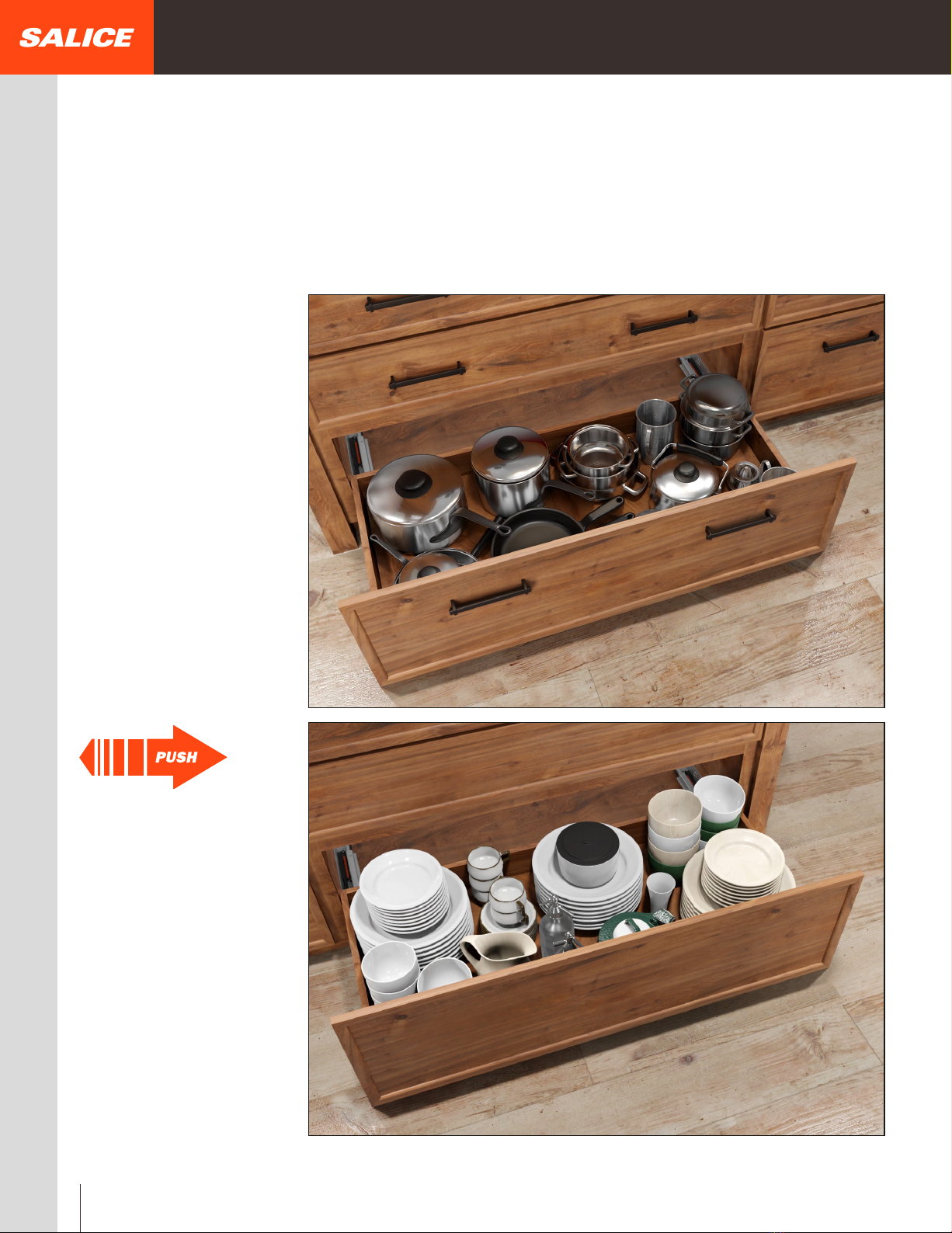
PUSH LENGTH BOX
WEBKIT1244664 381 mm 6 pcs right / 6 pcs left
WEBKIT1244666 457 mm 6 pcs right / 6 pcs left
457 mm 6 pcs right / 6 pcs left
WEBKIT1244943
533 mm 6 pcs right / 6 pcs left
WEBKIT1244947 533 mm 6 pcs right / 6 pcs left
WEBKIT1244946 610 mm 4 pcs right / 4 pcs left
WEBKIT1244945 686 mm 4 pcs right / 4 pcs left
WEBKIT1244944 762 mm 4 pcs right / 4 pcs left
CLIPS - LOCKING DEVICES BOX
AFCGXX3B 100 pcs right / 100 pcs left
AFCEX43B 100 pcs right / 100 pcs left
BRACKET BOX
AGSK7C5B 100 pcs
AGSK7C5B 100 pcs
TILT ADJUSTMENT LEVER BOX
AGLRXX3F0 12 pcs right / 12 pcs left
ARTICLE VERSIONS
S = SOFT CLOSE
P = PUSH TO OPEN
X = STANDARD FACE FRAME CABINET MEMBER
- face frame application without filler behind
frame
- face frame application with filler
behind frame
- frameless application
- for 381, 457, and 533 runner length
C = SHORT CABINET MEMBER FILLER
- face frame application with filler
behind frame
- frameless application
- for 457, 533, 610, 686 and 762
runner length
Example:
G7U6 _ ___ _ XB
BASIC PART NUMBER
DRAWER LENGTH
(381, 457, 533, 610, 686, 762 mm)
Part number composition - Ordering chart
Industrial packaging
10
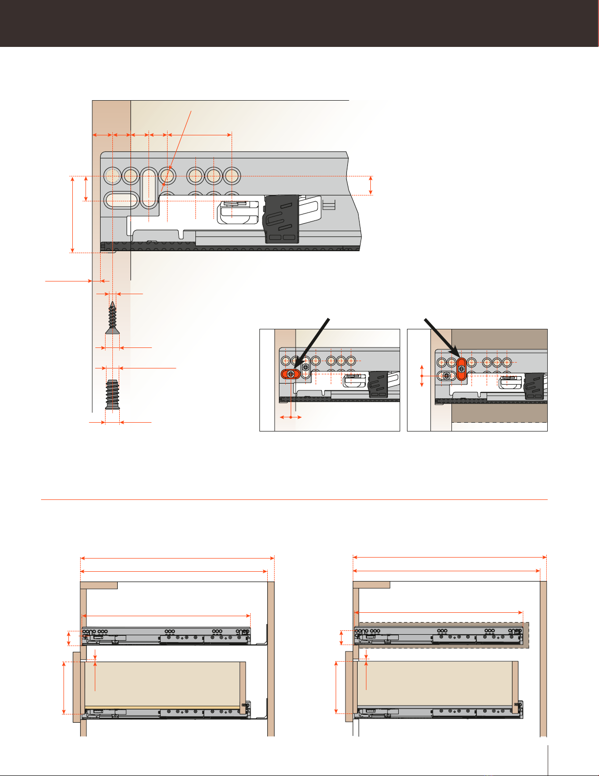
ASSEMBLY TYPE
Rear bracket
Rear bracket
Frame Fillers
Rear bracket
Frame Fillers
Frame Fillers
Frame Fillers
Frame Fillers
WEBKIT1244952
WEBKIT1244668
WEBKIT1244949
ASSEMBLY TYPE
Rear bracket
Rear bracket
Frame Fillers
Rear bracket
Frame Fillers
Frame Fillers
Frame Fillers
Frame Fillers
ADJUSTMENT
4W
2W
TYPE
Standard
Narrow
Packaging
Pair