manuals.online logo
Brands
  1. Home
  2. •
  3. Brands
  4. •
  5. Salsbury Industries
  6. •
  7. Indoor Furnishing
  8. •
  9. Salsbury Industries S-51000 Series User manual

Salsbury Industries S-51000 Series User manual

15" Wide See Through Lockers –S-51000 Series
Single Tier Installation Instructions
Phone: 1-800-562-5377 Int’l Phone: 323-846-6700
Fax: 1-800-562-5399 Int’l Fax: 323-846-6800
www.lockers.com [email protected]
Installation instructions are provided asgeneral guidelines. It is advised that a professional installer be consulted. Salsbury Industries assumes no product assembly or installation liability.
Copyright © 2020 Salsbury Industries. All rights reserved. Page 1 of 5
Thank you for selecting Salsbury’s 15" wide see through single tier lockers. These instructions are intended to assist you in assembling the lockers. Assembly of the various locker
components will be with #10 - 24 x 3/8” long slot less screws and #10 nuts (provided). Loosely fasten a screw and a nut into every set of mating holes with the screw heads positioned on
the outside of the locker or on the exposed surface.
One Wide Locker Assembly
Step 1: Attach the top shelf, bottom shelf, and the first single coat hook to the back
panel.
Step 2: Turn the back panel on its back with the shelves pointing upward. Attach the
first side panel, the left rear leg, and the hat shelf to the assembly from Step 1. On
15” deep lockers attach the double coat hook to the bottom of the hat shelf and attach
a second single coat hook to the first side panel. On 18” deep lockers omit the double
coat hook and substitute a single coat hook with a double bend (not shown) instead of
the second single coat hook (this will accommodate the coat rod).
Step 3: Attach the second side panel and the right rear leg to the assembly of Step 2.
On 15” deep lockers attach a third single coat hook. On 18” deep lockers substitute a
single coat hook with a double bend for the third single coat hook and install the coat
rod as shown on page 3. The locker chassis is now complete.
Step 4: Attach the pre-assembled door frame onto the assembly of Step 3.
Step 5: Tighten all fasteners checking for squareness of the locker while tightening.
Attach optional sloping hood, end bases or front base (see pages 4 and 5).
Step 6: Place the locker in the installed location and anchor to the floor, wall, or to
both. Individual job conditions will dictate the type of fastening anchors to use (not
provided).
Step 7: Fasten all lockers in a row together by installing fasteners provided through
the side panels. Installation is now complete.
SALSBURY INDUST
RIES
18300 Central Avenue, Carson, CA 90746-4008
15" Wide See Through Lockers –S-51000 Series
Single Tier Installation Instructions
Phone: 1-800-562-5377 Int’l Phone: 323-846-6700
Fax: 1-800-562-5399 Int’l Fax: 323-846-6800
www.lockers.com [email protected]
Installation instructions are provided asgeneral guidelines. It is advised that a professional installer be consulted. Salsbury Industries assumes no product assembly or installation liability.
Copyright © 2020 Salsbury Industries. All rights reserved. Page 2 of 5
Three Wide Locker Assembly
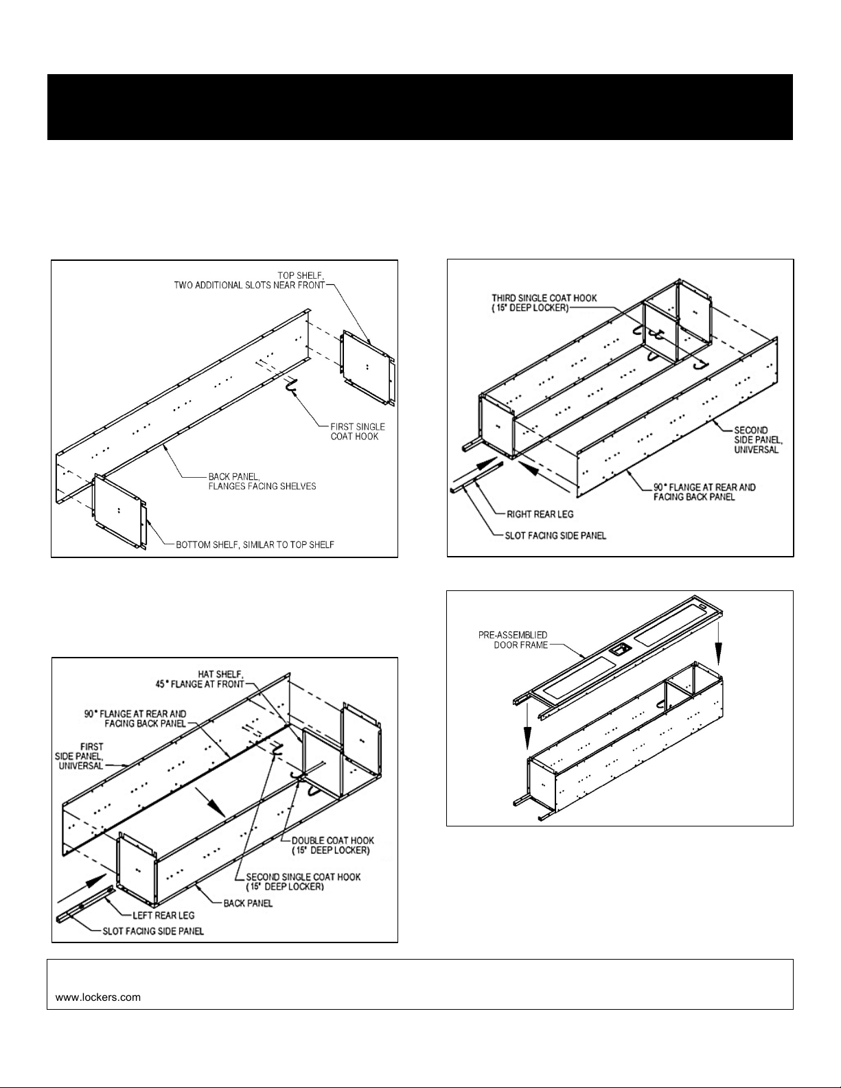
Step 1: Attach a top shelf, a bottom shelf, and the first single coat hook to a back
panel.
Step 2: Turn the back panel on its back with the shelves pointing upward. Attach the
first side panel, the left rear leg, and the first hat shelf to the assembly of Step 1. On
15” deep lockers attach the first double coat hook to the bottom of the first hat shelf
and attach a second single coat hook to the first side panel. On 18” deep lockers omit
the double coat hook and substitute a single coat hook with a double bend (not shown)
instead of the second single coat hook (this will accommodate the coat rod).
Step 3: Attach the second top shelf, the second bottom shelf, and an additional single
coat hook to the second back panel as in step 1.
Step 4: Simultaneously attach the assembly of Step 3 (second Step 1 assembly), the
second side panel, and the second hat shelf to the assembly of Step 2. On 15” deep
lockers attach the second double coat hook and attach two additional single coat
hooks to the second side panel. On 18” deep lockers omit the second double coat
hook and substitute two additional single coat hooks with a double bend (not shown)
instead of the single coat hooks and install a coat rod as shown on page 3.
Step 5: Attach the third top shelf, the third bottom shelf, and an additional single coat
hook to the third back panel as in steps 1 and 3.
Step 6: Simultaneously attach the assembly of Step 5 (third Step 1 assembly), the
third side panel, and the third hat shelf to the assembly of Step 4. Repeat the Step 4
coat hooks instructions to attach additional coat hooks and coat rods.
SALSBURY INDUST
RIES
18300 Central Avenue, Carson, CA 90746-4008
15" Wide See Through Lockers –S-51000 Series
Single Tier Installation Instructions
Phone: 1-800-562-5377 Int’l Phone: 323-846-6700
Fax: 1-800-562-5399 Int’l Fax: 323-846-6800
www.lockers.com [email protected]
Installation instructions are provided asgeneral guidelines. It is advised that a professional installer be consulted. Salsbury Industries assumes no product assembly or installation liability.
Copyright © 2020 Salsbury Industries. All rights reserved. Page 3 of 5
Three Wide Locker Assembly (continued)
Step 7: Attach the last side panel and the right rear leg to the assembly of Step 6. On
15” deep lockers attach the last single coat hook. On 18” deep lockers substitute the
last single coat hook with a double bend instead of the last single coat hook and install
the last coat rod. The locker chassis is now complete.
Step 8: Position the pre-assembled door frames onto the assembly of Step 7 then
fasten one by one.
Step 9: Tighten all fasteners checking for squareness of the locker while tightening.
Attach optional sloping hoods, end bases or front bases (see pages 4 and 5).
Step 10: Place the locker in the installed location and anchor to the floor, wall, or to
both. Individual job conditions will dictate the type of fastening anchors to use (not
provided).
Step 11: Fasten all lockers in a row together by installing fasteners (provided) through
the side panels. Installation is now complete.
Coat Rod Installation – 18” Deep Single Tier Locker Only
SALSBURY INDUST
RIES
18300 Central Avenue, Carson, CA 90746-4008
15" Wide See Through Lockers –S-51000 Series
Single Tier Installation Instructions
Phone: 1-800-562-5377 Int’l Phone: 323-846-6700
Fax: 1-800-562-5399 Int’l Fax: 323-846-6800
www.lockers.com [email protected]
Installation instructions are provided asgeneral guidelines. It is advised that a professional installer be consulted. Salsbury Industries assumes no product assembly or installation liability.
Copyright © 2020 Salsbury Industries. All rights reserved. Page 4 of 5
Sloping Hood Installation (Optional)
Step 1: Assemble the top panel to the rear panel with #10 - 24 x 3/8” slot less screws
and #10 nuts (provided). Position the flange of the top panel behind the rear panel.
Step 2: Assemble the side panels to the top panel and rear panel with #10 - 24 x 3/8”
long slot less screws and #10 nuts (provided).
Step 3: Attach the sloping hood to the top of the locker with #10 - 24 x 3/8” slot less
screws and #10 nuts (provided).
SALSBURY INDUST
RIES
18300 Central Avenue, Carson, CA 90746-4008
15" Wide See Through Lockers –S-51000 Series
Single Tier Installation Instructions
Phone: 1-800-562-5377 Int’l Phone: 323-846-6700
Fax: 1-800-562-5399 Int’l Fax: 323-846-6800
www.lockers.com [email protected]
Installation instructions are provided asgeneral guidelines. It is advised that a professional installer be consulted. Salsbury Industries assumes no product assembly or installation liability.
Copyright © 2020 Salsbury Industries. All rights reserved. Page 5 of 5
Front Base Installation (Optional)
Position the front base between the front legs of the locker with the flange upward.
Assemble to the locker with #10 - 24 x 3/8” slot less screws and #10 nuts (provided).
End Base Installation (Optional)
Position the appropriate end base (right or left) behind the corresponding side legs
(right or left) of the locker with the flange upward. Assemble to the locker with #10 - 24
x 3/8” slot less screws and #10 nuts (provided). Repeat for the other side.
SALSBURY INDUST
RIES
18300 Central Avenue, Carson, CA 90746-4008

Other Salsbury Industries Indoor Furnishing manuals

Salsbury Industries 3600 Series User manual

Salsbury Industries

Salsbury Industries 3600 Series User manual

Salsbury Industries 3700 Series User manual

Salsbury Industries

Salsbury Industries 3700 Series User manual

Salsbury Industries 77000 Series User manual

Salsbury Industries

Salsbury Industries 77000 Series User manual

Popular Indoor Furnishing manuals by other brands

Twin-Star International TC48-6092 manual

Twin-Star International

Twin-Star International TC48-6092 manual

Trasman 1471 FRAME Assembly manual

Trasman

Trasman 1471 FRAME Assembly manual

Forte SPRS12412 Assembling Instruction

Forte

Forte SPRS12412 Assembling Instruction

SUNS STOCKHOLM Assembly instructions

SUNS

SUNS STOCKHOLM Assembly instructions

Triarch 75238/14 Assembly instructions

Triarch

Triarch 75238/14 Assembly instructions

Next 686093 Assembly instructions

Next

Next 686093 Assembly instructions

Next BRONX 694625 Assembly instructions

Next

Next BRONX 694625 Assembly instructions

Poliman TURIM A4900 Assembly instructions

Poliman

Poliman TURIM A4900 Assembly instructions

BTFY 2500515 quick start guide

BTFY

BTFY 2500515 quick start guide

Sorelle 1070-E Assembly instruction

Sorelle

Sorelle 1070-E Assembly instruction

Lorell LLR60340 operating instructions

Lorell

Lorell LLR60340 operating instructions

HI MART NHC-609 manual

HI MART

HI MART NHC-609 manual

Furinno FNBL-22090 Assembly instruction

Furinno

Furinno FNBL-22090 Assembly instruction

calligaris MEDUSA CS/5080 manual

calligaris

calligaris MEDUSA CS/5080 manual

Branco BMU 28 Assembly instructions

Branco

Branco BMU 28 Assembly instructions

BCP SKY7279 instruction manual

BCP

BCP SKY7279 instruction manual

Core Products CRVTBSET4 Assembly instructions

Core Products

Core Products CRVTBSET4 Assembly instructions

Habitat Hana II 805801 manual

Habitat

Habitat Hana II 805801 manual

manuals.online logo
manuals.online logoBrands
  • About & Mission
  • Contact us
  • Privacy Policy
  • Terms and Conditions

Copyright 2025 Manuals.Online. All Rights Reserved.