Salt Dogg Direct Drive Hydraulic Replacement Tailgate... User manual

1
9049 Tyler Blvd. • Mentor, Ohio 44060
Phone (440) 974-8888 • Fax (800) 841-8003
www.saltdogg.com
Installation Instructions
Direct Drive Hydraulic
Replacement Tailgate Spreader
—continued inside
WARNING
During installation ensure that the truck is on level ground and
the spreader will be safely supported the entire process.
Table of Contents
Spreader Installation Instructions ............................ 1-2
Spinner Assembly Instructions................................ 3-4
Spinner Assembly Drawing ........................................ 4
Hydraulic Installation ............................................... 4-5
Operating Instructions .............................................5-6
Parts lists................................................................. 7-8
REPLACEMENT TAILGATE SPREADER WARRANTY
This warranty replaces all previous warranties and no employee
of this company is authorized to extend any additional warranties,
or agreements, or implications not explicitly covered herein.
Buyers Products Company warrants all parts of the product to
be free from defects in material and workmanship for a period
of (1) one year from the date of original installation. Parts must
be properly installed and used under normal conditions. Normal
wear is excluded.
Any part which has been altered, including modification,
misuse, accident, or lack of maintenance will not be considered
under this warranty. The sole responsibility of Buyers Products
Company under this warranty is limited to repairing or replacing
any part(s) which are returned, prepaid, 30 days after such
defect is discovered, and returned part(s) are found to be
defective by Buyers Products Company.
Authorization from Buyers Products Company must be
obtained before returning any part. The following information
must accompany defective parts returned to Buyers Products
Company: RMA#, spreader model, serial number, date installed,
and distributor from whom it was purchased. Buyers Products
Company shall not be liable for damage arising out of failure of
any unit to operate properly, or failure, or delay in work, or for
any consequential damages. No charges for transportation or
labor performed on any part will be allowed under this warranty.
Note: These instructions are for typical
installation. Your truck application may
require additional fabrication.

2
9049 Tyler Blvd. • Mentor, Ohio 44060
Phone (440) 974-8888 • Fax (800) 841-8003
www.saltdogg.com
LATCH PINS
(TWO SIZES PROVIDED)
HINGE BRACKET
SIDE EXTENDER
GUSSETS
1. Aligning and Mounting the Spreader:
A. Remove the truck’s tailgate and store it in a
safe location.
B. Position the spreader at the rear of the truck,
centered, and with the spreader slightly above
the surface of the bed.
NOTE: The spreader should be lifted using
the hook welded to the body. Clamp the
spreader in this position.
C. The spreader is supplied with two sizes of
hinge pins and hinge brackets with two sizes of
holes.
D. Determine which parts best work with your
truck body and fit them up and tack weld in
place.
NOTE: If required, different size pins or
brackets are the responsibility of the installer.
E. Remove the spreader from the body and fully
weld the mounting components to the spreader.
NOTE: It is the responsibility of the installer
to ensure that the final installation is
completed properly and as secure as the
original tailgate.
F. Cut off any extra material as desired then
reattach the spreader to truck in order to mount
the spinner assembly.
2. Alternate Mounting:
A. Another option for mounting is to use the
included side extenders. These are to be bolted
to the sides of the spreaders using the included
carriage bolts and should be mounted flush with
the truck side surface of the spreader.
NOTE: Side Extenders should be attached
so slotted holes line up with existing holes in
the spreader body. This will allow clearance
for positioning the bottom hinge pin.
B. Use the included gussets, 2 per side, to
reinforce the side extenders as close to the
mounting hardware as possible.
C. If desired, additional gussets or supports
may be added. (NOT SUPPLIED)

3
3. Spinner assembly installation: (See installation
drawings on pages 3 and 4.)
A. Attach the spinner shield (Item 2) to the spinner
frame (Item 1) using (2) 5/16-18 x 1-1/4 cap screws,
5/16 flat washers and (2) 5/16-18 hex flange nuts.
B. Attach the spinner disk sub assembly to the
hydraulic motor on the spinner frame and tighten the
set screw in the disk collar.
Note: Be sure to lubricate the hydraulic motor
shaft generously with Never Seez lubricant before
assembling.
C. Attach the spinner frame assembly to the lower
tray of the spreader with the hinge rod and attach (2)
hairpin cotter pins.
D. The leveling mechanism may now be mounted.
Park truck on flat, level surface. With spinner
assembly in level position, carefully measure “L” and
“D” distances. Use any of 3 available holes in height
adjustment bracket. Locate bar or spinner lug such
that ½” hole will position with D1=D and L1=L. Modify
angle if necessary.
E. Secure bar or spinner lug to the truck frame.
F. Attach parallel linkage rods to heights adjustment
bracket and angle. Secure them using ½” washers
and hair pins.
G. Clamp parallel linkage rods together. To verify
leveling action, slowly raise the dump. Be sure that
spinner motor assembly and linkages do not have
any interference with truck body and it does not have
contact with the road. After checking weld parallel
linkage bars together.
H. Keeping the spinner assembly level, remove the set
screw from the clamp collar and secure the spinner
frame in place using the spinner assembly lock.
Truck Frame
Hinge Rod
Spinner
Frame
Spinner Lug or Bar
Spreader
Dump Body
Hinge
Bar
Parallel
Linkage
Hole
L1 L
Parallel Linkage, Spinner Frame & Bar
Installation Drawings

4
3
2
1
8
5
6
7
4
Parallel Linkage, Spinner Frame & Bar Installation Drawings (cont.)
Bill of Materials
ITEM QT Y. DESCRIPTION STAINLESS
1 1 Spinner Frame Assy. 3018416
2 1 Spinner Shield 3006659
3 1 Spinner Disk Assy. 3001472A
4 2 Linkage Rods, Welded 924F0012
ITEM QT Y. DESCRIPTION STAINLESS
5 1 Hinge Rod 3006646
6 1 Spinner Lug 3006645
7 1 Bar 924F0014
8 1 Height Adjustment Bracket 3017175
Hydraulic Flow Diagram
Valve 1/2" Quick Disconnects
3/4" (1)
Wire Hose
3/4" (1) Wire Hose
1/2" (1) Wire Hose
1/2" (1) Wire Hose
1/2" (1) Wire Hose
Auger Motor
CW Rotation
Ball
Valve
Spinner Motor
CCW Rotation
3/4" Quick
Disconnects
3/4" (2) Wire Hose
1-1/4" Spiral
SuctionHose
3/4" (2) Wire Hose
1/2" (1) Wire Hose
Tank
Pump
3
14
Hose
5
T
A
P
S
Bill of Materials
ITEM PART NO. QT Y. DESCRIPTION
1HV715 1Dual Flow Regulator Valve
2HVC1 1Dual Flow Regulator Console
3SMR15 1 15 Gallon Reservoir
43008523 1
Ball Valve Assembly
53008112 1Hose
Hydraulic Installation Instructions
A. During assembly take precautions to keep all
hydraulic components as clean as possible.
B. Allow enough hose length to prevent kinking
and stretching of the hoses and to permit raising
the dump body. Support long hoses with wire
ties or clamps.
C. Protect hoses from wear caused by sliding
and/or vibration.
D. For proper rotation of auger and spinner
motors, hoses may be reversed.
Note: Use of a pipe joint sealant compatible
with hydraulic oil is recommended for all
screw fittings.
E. Use swivel type hose ends to connect hoses
to flow valve. Damage to valve body may occur
if the fittings in flow valve are over tightened
F. To achieve a positive shutoff of the auger motor,
the inlet flow must pass through the ball valve (pre-
mounted to the spreader) & the supplied hose must
connect the ball valve to the auger’s hydraulic motor
as shown in the figures on the bottom of page 4.
(Inspection of this hose is recommended to ensure no
damage has occurred during shipping)

5
G. Using hose number 3008112, insert one end into
the bottom of the ball valve assembly. Insert the other
end into the LH port (when looking from rear) of the
hydraulic motor.
Operating Instructions
CAUTION
A. Be sure everyone is standing clear.
B. Be alert for anything that may require shutting
down the system.
C. Before working in or around spreader equipment, be
sure all hydraulic controls are moved to off position.
1. Pre-start up.
A. Use high grade non foaming hydraulic oil to fill
reservoir about 3/4 full.
B. Position valve on/off lever to off.
C. Move auger and spinner knobs on the valve to the
open position.
D. Engage PTO and circulate hydraulic oil for several
minutes to warm up.
E. Move valve on/off lever to on.
F. Inspect hydraulic system for leaks.
G. Check auger and spinner to see if they are working
properly.
H. Refill reservoir to 3/4 full.
I. Hydraulic system should now be ready for use.
2. Initial use of spreader
A. Shut off spinner and auger knobs and position
the on/off lever to on. Engage the PTO and allow the
hydraulic system to warm up.
B. Open the cover plate and secure vertically with
locking brackets.
C. Open dump body tailgate as wide as possible from
bottom without bearing against cover plate. Set stop
chains.
D. Position spinner assembly to the far left (drivers
side), tighten clamp. Determine placement of material
at various spinner and auger speeds by spreading
a small amount of material (Far left position used to
spread (3) three or (4) four lane highway from right
lane).
E. Position spinner assembly to the far right
(passenger side), tighten clamp. Determine placement
of material at various spinner and auger speeds
by spreading a small amount of material (Far right
position used to spread (4) four lane highway from left
lane).
F. Changing auger and spinner speeds on the valve
and placing spinner at various positions from left to
right will produce various spread patterns.
Insert other end
of hose into port
on hydraulic motor
flow here
Attach inlet
of ball valve
into bottom
end of hose
Insert one
3008112

6
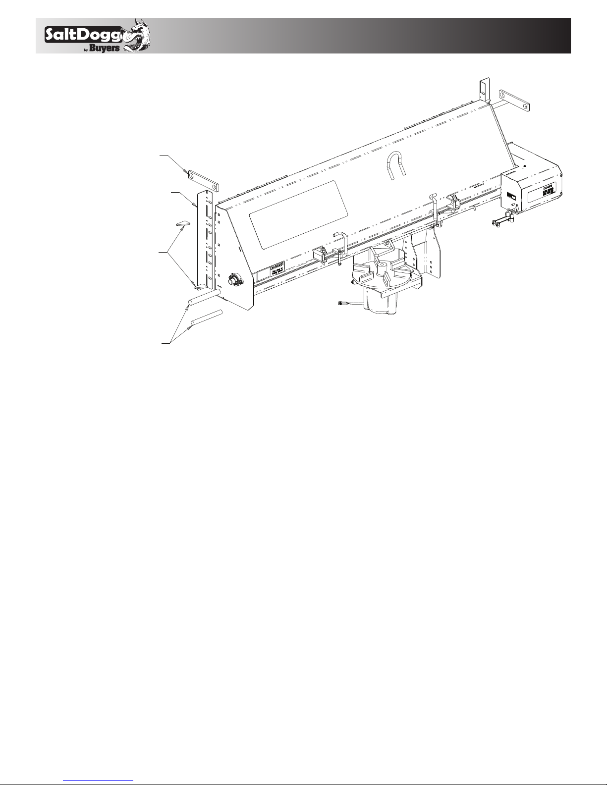
3. Using the Auger Lock-out System
A. Shut off spinner and auger and position the main
hydraulics on/off lever to off.
B. Remove the lock-out pin, rotate the handle, and
insert the pin through the holes in the handle and
the bracket to prevent accidental engagement of the
hydraulics. (see illustration below)
C. The lower tray may now be opened for servicing
the auger.
D. After servicing, first close and lock the tray then
reverse the steps to move the handle and pin back to
their original positions. BE SURE TO REINSERT THE
LOCK-OUT PIN THROUGH THE HOLES IN THE
HANDLE AND THE BRACKET.
E. Turn the main hydraulics back on and the spreader
is ready for operation.
DANGER
Before working in or around the auger area, the valve
control lever must be in the off position. Disengage PTO,
shut off engine, and follow the auger lock-out instructions.
MAKE SURE THE LOCK-OUT PIN IS ALWAYS USED IN BOTH
THE ON AND OFF POSITIONS. After servicing is complete,
reverse the process to restore the spreader function.
NEVER PUT ANY PART OF YOUR BODY INSIDE THE AUGER
AREA OF SPREADER.
Auger ON
Auger OFF
4. Miscellaneous
A. Valve setting changes may be made with truck in
motion.
B. By moving on/off lever to the off position, spinner
and auger may be stopped at the same time without
changing their valve settings.
C. Close cover plate flat over spreader trough and
lock in place for normal use of dump truck. Tailgate
may be opened from top or bottom.
D. When truck is used for extensive hauling the
spinner assembly should be removed.
E. If auger clogs, shut off spinner, open auger knob
valve and increase the engine speed. With the engine
at a higher speed, move the valve lever from the on to
the off positions rapidly; repeat as needed. This action
may unclog the auger. If this action fails to free the
auger, manual unclogging will be required.
CAUTION
Position the valve on/off control lever in the off position
when the spreader is not in use or is removed. In the
event the valve on/off control lever is left in the on posi-
tion, a heat problem may occur as the pump continues to
pump oil to the hydraulic valve. This could cause a hose
to burst spraying hot oil.
Recommended Maintenance
A. Warm up hydraulic system before using.
B. Keep the reservoir 3/4 full with high grade
nonfoaming hydraulic oil.
C. Use precautions to keep contaminants from getting
in reservoir when filling.
D. Quick connects are a prime source of contamination.
1. Clean quick connects before connecting or
disconnecting them.
2. Protect quick connects from contaminates.
E. Lubricate all bearings with suitable type grease
on a regular basis. More frequent lubrication is
recommended during periods of heavy use.
F. Lubricate the spinner hinge rod periodically.
G. Maintain the proper lubrication level in all
gearboxes with SAE 90 gear lubricant.
H. When not in use, keep the spreader tray empty to
prevent freezing of material around auger in extremely
cold weather.
I. To extend the life of your spreader:
1. Hose down and clean after each use.
2. Repaint and/or oil after each season.

7
9049 Tyler Blvd. • Mentor, Ohio 44060
Phone (440) 974-8888 • Fax (800) 841-8003
www.saltdogg.com
ITEM PART NO. QT Y. DESCRIPTION
13032173 1Bottom Tray - Center Discharge
1B 3032206 Bottom Tray - Driver Side Discharge
23032188 1Auger - Center Discharge
2B 3032191 Auger - Driver Side Discharge
33032179 2Screen
41420016 2Cotter Pin
5HP12 2Cotter Pin
63032181 1Plate,Anti-Spill
73027109 1 Cam Handle - CW
830 27110 1 Cam Handle - CCW
93001247 2 Nut,Nylon Locking 5/8-11
10 3001249 2 Screw,Hex Head Cap, 3/8-16 x 3
11 FNE038016044SS 5 Nut,Nylon Locking 3/8-16
12 FCS038016100SS 7 Screw,Hex Head Cap,3/8-16 X 1
13 FCS038016125SS 2 Screw,Hex Head Cap,3/8-16 X 1.25
14 9240087 1Gasket,Felt
ITEM PART NO. QT Y. DESCRIPTION
15 9240087 1Bearing
16 3014756 2Nut,Nylon Locking,7/16-14
17 3008549 2 Screw,Hex Head Cap,1/4-20 x 1/2
18
FWL025050006SS
2Washer,Locking,1/4
19 3008523 1Ball Valve Assembly
20 9240083 1Sleeve,Auger Adapter
21 3001250 1 Screw,Hex Head Cap,1/2-13 x 3
22 924F0084 1Adapter,Motor
23 3001253 1Nut,1/2-13
24 3001367 1Plate,Motor Mount
25 CM074P 1Motor
26 3001522 3 Bolt,Carriage,1/2-13 x 1
27 3001523 3Nut,1/2-13
28 FCS038016075SS 4 Screw,Hex Head Cap,3/8-16 x 3/4
29
FWL038069009SS
4Washer,Locking,3/8
Spreader Assembly Parts List
Bill of Materials
1
1b
2
2b
33
44
5
7
8
9
9
10
10
11
11
11
12
13
14
15
16
17 18
19
20 22
21 23
24
25
26
27
28
29
FRAME SHOWN FOR REFERENCE ONLY
ACTUAL FRAME MAY BE DIFFERENT
6

83032218 Rev. A
Hardware Box Parts List -
Part No. 3032219
ITEM PART NO. QT Y. DESCRIPTION
13006645 1Angle,Spinner Lug
23006646 1Rod,Hinge
3924F0012 2Parallel Linkage
43017175 1Bracket,Height Adjustment
53032180 4Gusset,Side Extension
63032177 2 Plate,Side Extension
73032176 2Bar,Pivot
83032175 2Pin,Pivot,1.25 Diameter
93032204 1Pin,Pivot,1.00 Diameter
10 3018416 1Frame Asm, Spinner Motor
11 3006659 1Deflector, Spinner
12 3001472A 1Spinner Disk Asm
13 3008112 1Hose,Motor
14 3032222 1Hardware Bag
Bill of Materials
2
1
3
4
6
7
5
8
9
10
11
14
12
13
Table of contents
Other Salt Dogg Automobile Accessories manuals
Popular Automobile Accessories manuals by other brands

TigerTough
TigerTough 65513 installation guide

Silvercrest
Silvercrest SFA 4.1 E1 operating instructions

Steelcraft
Steelcraft 50320 installation instructions

Air Lift
Air Lift RideControl 59544 installation guide

Horn Tools
Horn Tools HSW995GRAPPLATE Mounting instructions

Pet Gear
Pet Gear Travel Lite TL9371RF instruction manual

SNUG TOP
SNUG TOP UT PRO MT3 Installation instructions & owner's manual

Let's Go Aero
Let's Go Aero BLACK BOX Assembly, installation and operation instructions

Taramp's
Taramp's HV160.000 instruction manual

Cellularline
Cellularline interphone instruction manual

i-PRO
i-PRO RH519 user guide

Steelcraft
Steelcraft hd10410 installation instructions