Salt Dogg TGS05B User manual

1
Installation Instructions
TGS05B
Fig. 1 Mounting
—continued inside
SAFETY PRECAUTIONS
WARNING
Observe the following Safety Precautions before,
during and after operating this spreader. By following
these precautions and common sense, possible injury
to persons and potential damage to this machine may
be avoided.
1. Read this entire Owners Manual before operating
this spreader.
2. Read all safety decals on the spreader before
operating.
3. Verify that all personnel are clear of the spreader
spray area before starting or operating this spreader.
4. Do not adjust, clean, lubricate or unclog material
jambs without first turning off the spreader.
5. Make sure the spreader is securely fastened to the
vehicle in accordance with this manual.
6. Do not operate a spreader that is in need of mainte-
nance or repairs.
7. Always disconnect the battery before removing or
replacing electrical components.
SPREADER ASSEMBLY
Check contents of box against parts list to make
sure all components are included. When ordering
replacement or spare parts refer to parts list for part
numbers.
INSTALLATION
1. Locate and mark center of tailgate.
2. Assemble Angles (18, 19) and Braces (20) as
shown in Fig.1 Use 3/8" carriage bolts, flat washers
and nuts. Do not tighten fasteners at this moment.
3. Center assembly on top of tailgate. Lower angle
must be flush with top and inside surfaces of tailgate.
4. Position braces (20) on top of side rails. Using
holes in braces as guides mark and drill holes for 3/8"
screws.
5. Attach braces to side rails using 3/8" screws, flat
washers and nuts.
6. Center spreader assembly on top of rear bumper
and align with holes in Angle (18).
7. Using holes in spreader frame as guides, mark and
drill holes for 3/8" screws in rear bumper.
8. Assemble spreader to Angle (18) and rear bumper.
Adjust position of Angles (18, 19) to bring spreader
into vertical position. Tighten all screws at this
moment.
Chart A Torque
1/4-20 6.0
5/16-18 11.0
3/8-16 20.0
BOLT NUT SIZE TORQUE (FT-LBS)
9049 Tyler Blvd. • Mentor, Ohio 44060
Phone (440) 974-8888 • Fax (440) 974-0165
Toll-Free Fax 800-841-8003 • saltdogg.com

2
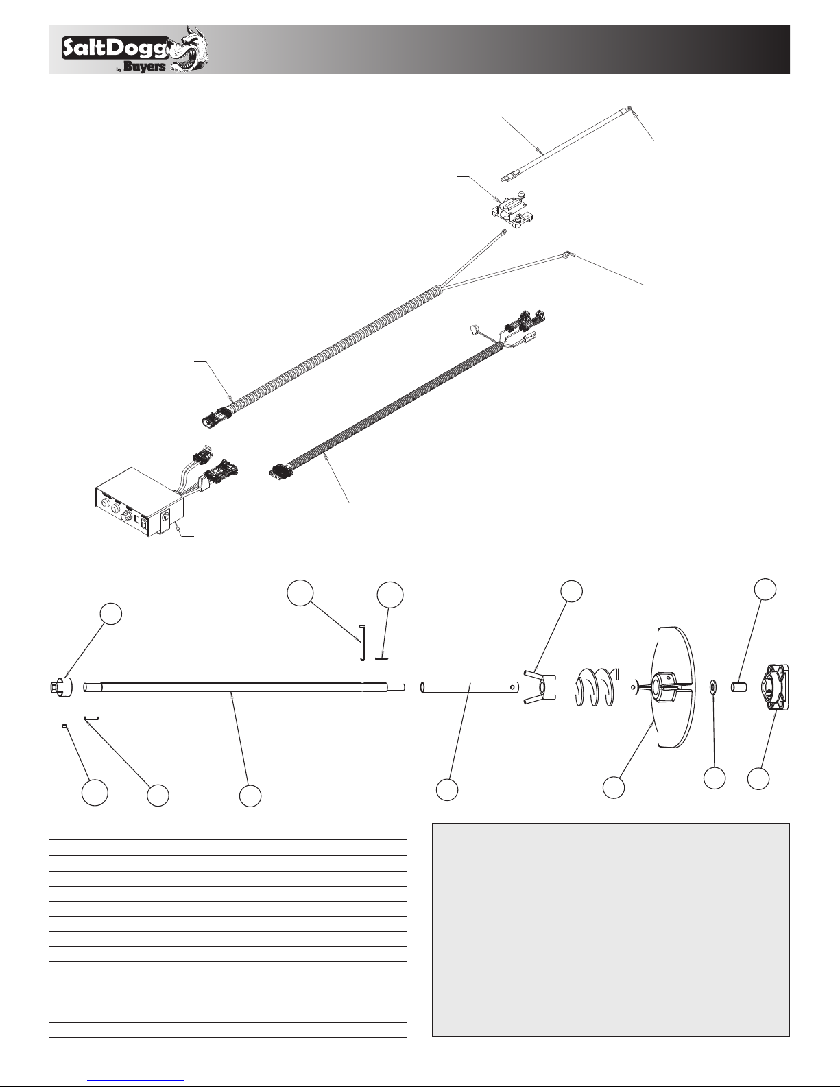
ELECTRICAL INSTALLATION
WARNING!
Do not drill holes into fuel tanks, fuel lines,
through electrical wiring, etc that may be
damaged by drilling.
To insure good performance of your spreader, check
the condition of truck’s electrical system. Using digital
voltmeter, check alternator and battery voltage. With
engine running and head lights and heater fan ON
good voltage reading should fall between 13.0 and
15.3 volts. If voltage reading falls out of this range,
check and adjust your electric system.
NOTE: Always disconnect battery before attempt-
ing to install electrical components on your
vehicle.
• Mount the controller in a convenient location in the
truck cab. It is recommended not to mount the con-
troller directly in front of heat vents.
• Route both wire harnesses into truck cab through
firewall (it maybe necessary to drill holes). Insulate
hole to avoid water leaks.
• Insure no wires are nicked or damaged during
installation.
• Connect the 4-pin connecter on the wire harness to
the control box.
• Connect the 2-pin connector on the power cable to
the control box.
• Lay out a path for the power cable to the bat-
tery, use quick ties to secure power cable. DO NOT
CONNECT TO BATTERY AT THIS TIME!
• Lay out path for wire harness to the rear of the vehi-
cle. It is recommended to stay clear of the exhaust
system. Excess heat can damage the wire harnesses.
Use quick ties to secure harness to underbody.
• Connect the wire harness to the motor.
• Connect the power and ground cables directly to
the battery.
• Insure all functions of the controller are working
properly.
Observe spinner direction of rotation. The correct
direction is counter clock wise when looking
inside hopper from the top. If direction is clock
wise reverse wires between Motor and Wire
Harness.
IMPORTANT!
Make sure all wires are securely attached to
vehicle or spreader’s frame. Use wire ties and/
or wire clamps to attach wires. All excess wires
must be rolled into bundles and attached to
vehicle or spreader.
SPREADER MAINTENANCE
1. This spreader is designed to use lose free floating
materials such as #1 dry Rock Salt. Using different
grades and/or wet material will affect spreader per-
formance. Wet material can “bridge” and stop floating
onto spinner disk.
2. Make sure lid is installed and latches are secured
when spreader is in use.
3. Do not leave material in hopper between uses.
4. Do not drive with material in hopper.
5. Always clean/ wash hopper and lubricate bearing
at the end of the day.
6. Spray lubricant around motor shaft to prevent
water from penetrating into the motor.
7. Apply dielectric grease to all electrical connectors
between uses and for long term storage.
CAUTION!
DO NOT ATTEMPT TO INSTALL OR REMOVE
SPREADER WITH MATERIAL IN IT.

3
Bill of Materials
1 3002494 1 Channel Motor MTG
2 3009476 1 Motor
3 3011395 1 Bushing
4 0208470A 1 Assembly Coupling 1/2 Bore
5 - 4 Screw, Cap Hex HD 1/4-20 x SST
6 - 4 Washer, 1/4" Spring Lock SST
7 - 4 Nut Hex 1/4-20 SST
ITEM PART NO. QTY. DESCRIPTION
Bill of Materials
1 3006702 1 Assembly, Frame Weldment TGS05B
2 3013285 1 Assembly, Hopper with Insert
3 3006707T 1 Bracket, Motor Mounting TGS05B
4 3003035 1 Shaft Assembly, TGS05 Auger
5 - 4 Washer, Flat 3/8 USS SST
6 - 4 Screw, HHC 3/8-16 x 2-1/2 Gr 5 Zp
7 - 8 Nut, Nylock 3/8-16 x 7/16 Zinc
8 0208260 1 Strap, TGS05 Hopper Support
9 - 1 Screw, HHC-3/8-16 x 1.25 Gr 5 Zinc
10 3002486 1 Shield Spinner TGS05A
11 3002502 1 Assembly Motor Drive TGS05A
12 BFP-321 1 Plug, 2" Square Closure
13 0208470C 1 Spider, Solid Center
14 3002495C 1 Cover Motor Drilled
15 - 1 Screw, Sheet Metal #12 x 3/4
16 3002511 1 Assembly Lid TGS05A
17 3000626P 1 Keeper Latch WJ201 Black
18 3002895 1 Mount Angle, Spreader
19 0200100 1 Mount Angle, Tailgate
20 0203100 1 Mount Brace
21 - 1 Screw, BHC #10-24 x .75 SST
22 - 1 Nut Elastic Stop 10-24 SS
ITEM PART NO. QTY. DESCRIPTION
Fig. 2 Main Assembly
Fig. 3 Motor Base Assembly

4
1
2
3
4
5
6
7
8
9
10 11
12
3014856_B
WARRANTY
Buyers Products Co. warrants all truck/trailer hardware manufac-
tured or distributed by it, to be free from defects in material and
workmanship for a period of one year from date of shipment. Parts
must be properly installed and used under normal conditions.
Any product which has been altered, including modification, mis-
use, accident or lack of maintenance will not be considered under
warranty. Normal wear is excluded. The sole responsibility of Buyers
Products Co. under this warranty is limited to repairing or replacing any
part or parts which are returned, prepaid, and are found to be defective
by Buyers Products Co. Authorization from Buyers Products Co. must
be obtained before returning any part. No charges for transportation
or labor performed on Buyers’ products will be allowed under this
warranty.
Fig. 4
Bill of Materials
1 3007683 1 Auger Weldment, TGS05
2 0208460 1 Bushing, TGS05 Auger
3 0208360 1 Shaft, TGS05 Spinner
4 3005706 1 Spinner, Poly TGS01, TGS05, TGSUVPRO
5 - 1 Washer Flat 1/2" SAE Zinc
6 3004245 1 Bushing, Bronze Oilite, 1/2" ID x 5/8 ODx1"
7 0208470B 1 Assembly, Coupling 5/8" bore
8 3003032 1 Bearing, 5/8" bore, 4 hole
9 KS301 1 Key, 3/16 x 1 Sq.
10 1420014 1 Pin, Clevis 1/4 x 2.5
11 - 1 Cotter Pin, 5/64 x 3/4
12 - 1 Screw Set, Soc. Cup Point 1/4-20 x 1/4 SS
ITEM PART NO. QTY. DESCRIPTION
Wiring Diagram
9049 Tyler Blvd. • Mentor, Ohio 44060
Phone (440) 974-8888 • Fax (440) 974-0165
Toll-Free Fax 800-841-8003 • saltdogg.com
3011864
3008620
3035934
CB50PB
3001379
BATTERY POSITIVE
BATTERY NEGATIVE
Table of contents
Other Salt Dogg Automobile Accessories manuals