OWNER’S MANUAL V.1 ENGLISH
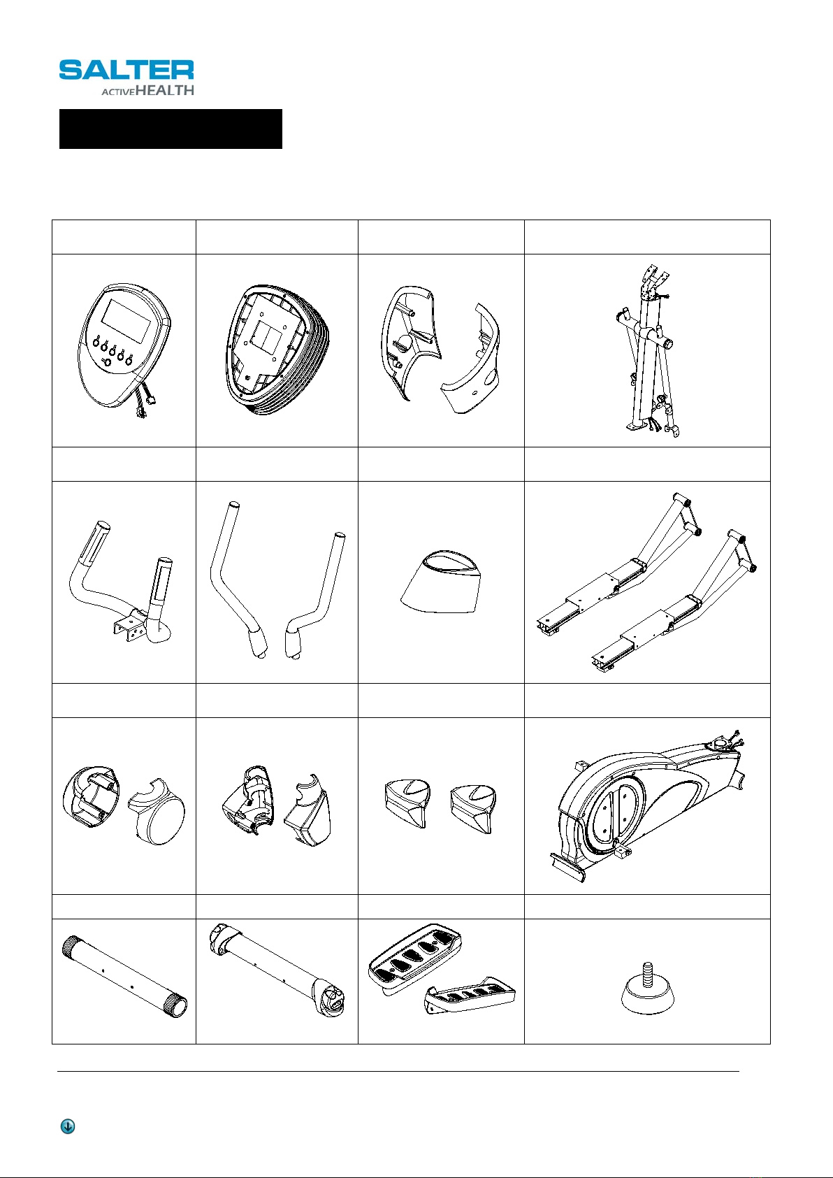
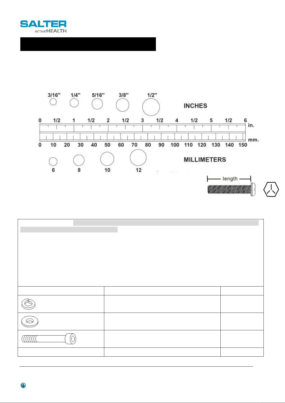
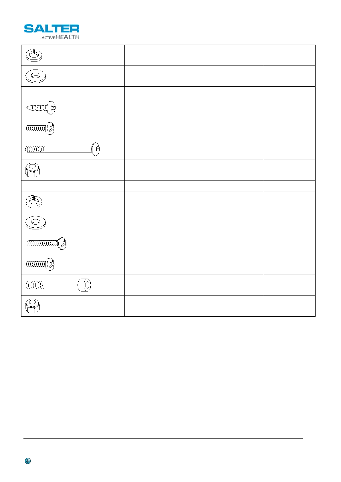
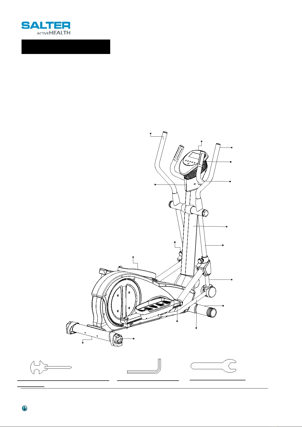
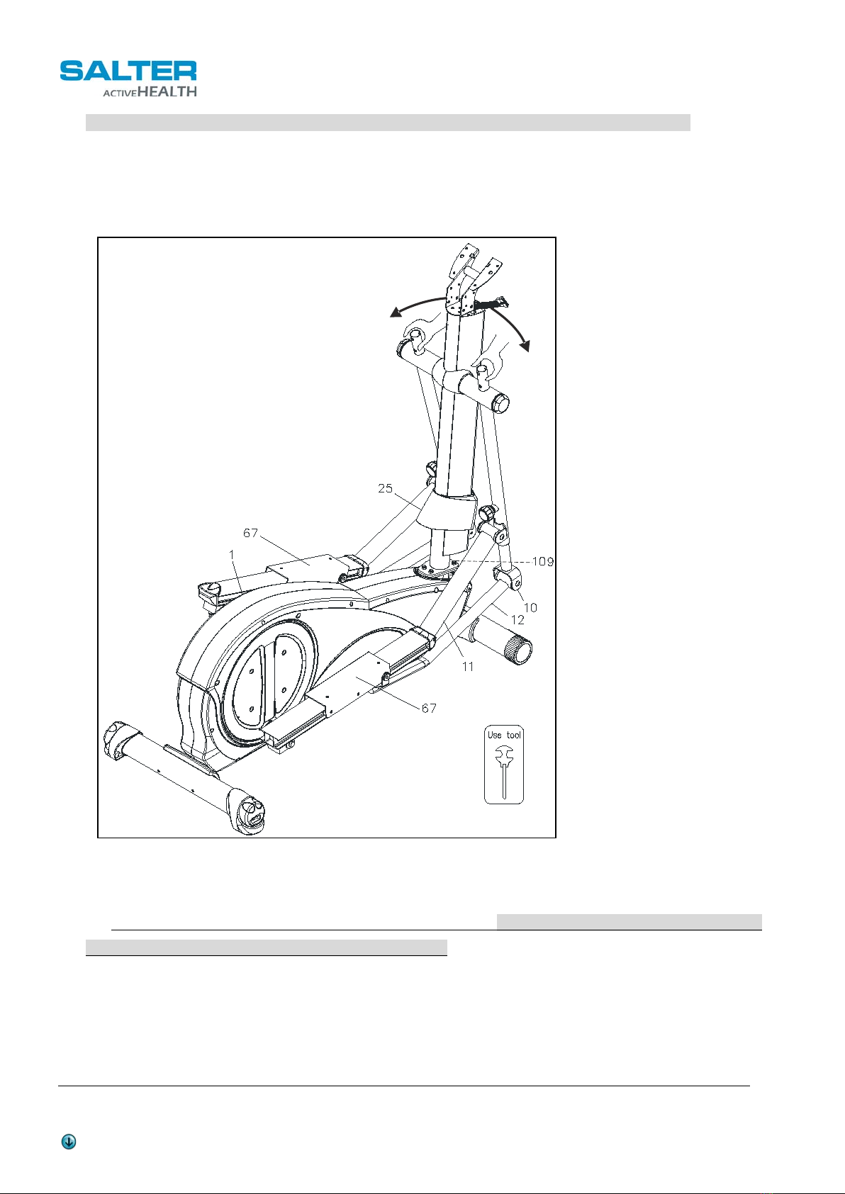
PT-323/N E-LINE ELLIPTICAL
This manual is available at www.salter.es
“SAFETY INSTRUCTION”
WARNING: To reduce the risk of serious injury, read the following safety instructions before using
the ELLIPTICAL TRAINER
1. Read all warnings posted on theequipment
2. Read this Owner's Manual and follow it carefully before using the equipment. Make sure that it is properly assembled and
tightened before use
3.We recommend that two people be available for assembly of this product
4. Keep childrenand pets away from the equipment. Do not allow children and pets to use or playon the equipment .Always keep
children and pets awayfrom the equipment when it is in use
5. It is recommended that you place this exercise equipment on an equipment mat
6. Set up and operate the equipment on a solid level surface. Do not position the equipment on loose rugs or uneven surfaces
7. Inspect the equipment for worn or loose components prior to each use
8. Tighten /replace any loose or worncomponents prior to using the equipment
9. Consult a physician prior to commencing an exercise program. If, at any time during exercise, you feel faint, dizzy, or
experiencepain, stop and consult your physician
10. Follow your physician's recommendations in developing yourown personal fitness program
11. Always choose the workout which best fits your physical strength and flexibilitylevel. Know your limits and train within them.
Always use common sense when exercising
12. Before using this product, please consult your personal physician for a complete physical examination.
13. Do not wear loose or dangling clothing while using theequipment
14. Never exercise in bare feet or socks; always wear correct footwear, such as running, walking, orcross-training shoes
15. Be careful to maintain your balance while using, mounting, dismounting, or assembling the equipment loss of balance may
result in a fall and serious bodily injury
16. Keep both feet firmlyand securely on the Foot Pedals while exercising
17. The equipment should not be used bypersons weighing over 300 pounds /136 kgs
18. The equipment should be used byonly one person at a time
19. The equipment is for semi-commercial, light-commercial and home usage
20. Maintenance: Replace the defective components immediately and / or keep the equipment out of use until repair the equipment
completely.
21. Make sure that adequate space is available for access to and passage around the equipment; keep at least a distance of 1
meter from any obstruction object while using the machine.
WARNING: Before starting any exercise or conditioning program you should consult with your personal physician to see
if you require a complete physical exam. This is especially important if you are over the age of 35, have never exercised before, are
pregnant, or sufferfrom anyillness.