Section Page
1 Introduction
Using this Manual...................................................................................................1-1
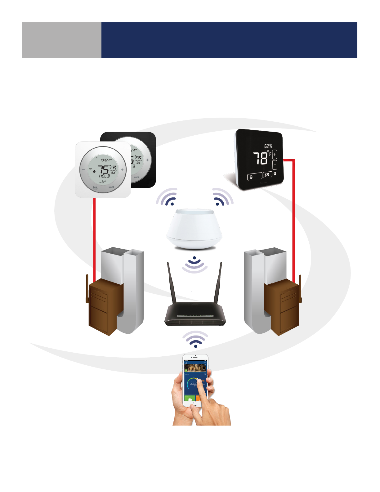
System Overview ...................................................................................................1-2
2 ST880ZB Optima Zigbee Thermostat
Included Parts / Installation Tools ....................................................................................2-1
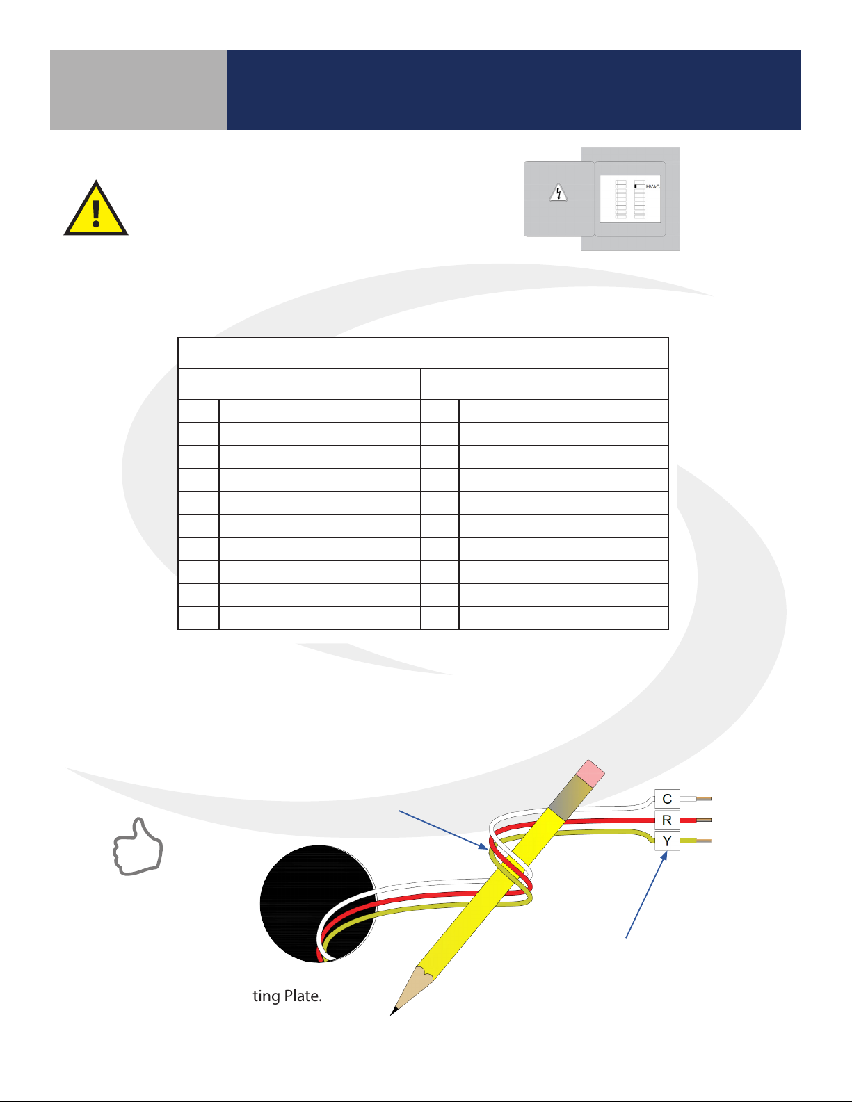
Installation – Mounting & Wiring ....................................................................................2-2
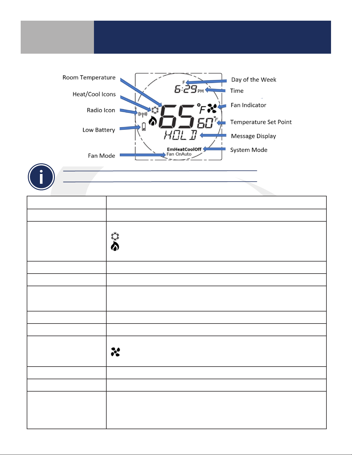
Controls & Display ..................................................................................................2-5
Home Screen .......................................................................................................2-6
Pairing Instructions .................................................................................................2-7
Time & Date .......................................................................................................2-10
Settings ...........................................................................................................2-11
Firmware Update ..................................................................................................2-12
Factory Reset ......................................................................................................2-13
3 ST898ZB Optima S Thermostat
Included Parts / Installation Tools ....................................................................................3-1
Installation – Mounting & Wiring ....................................................................................3-2
Display Boot Sequence..............................................................................................3-4
Pairing Instructions .................................................................................................3-4
Initial Conguration.................................................................................................3-6
Home Screen & Controls ............................................................................................3-8
Operation ..........................................................................................................3-9
Conguration......................................................................................................3-10
4 Remote Thermostat Operation & Parameters
Optima & Optima S Parameters......................................................................................4-1
Schedules & Status Options .........................................................................................4-2
Setting Up Thermostat Schedules ...................................................................................4-3
Using Status to Control Thermostats.................................................................................4-5
5 Troubleshooting
Troubleshooting Information........................................................................................5-1
SALUS Connected Wireless System Guide
Contents: Wireless HVAC Thermostats
Module 4
i