manuals.online logo
Brands
  1. Home
  2. •
  3. Brands
  4. •
  5. Salus
  6. •
  7. Thermostat
  8. •
  9. Salus HTR2420 User manual

Salus HTR2420 User manual

Note: The following designations are used interchangeably for products:
= SL
= NSB
HTR24(20) is a surface-mounted (or on a ush-box) room thermostat
dedicated for surface heating / cooling control, characterized by high thermal
inertia. It is connected to the wiring centre, through which you can lower the
set temperature on it, receiving a signal NSB (night temperature reduction)
from the weekly thermostat. The room temperature could be set by knob
use. Thanks to the built-in algorithms, it oers much better temperature
control accuracy than traditional mechanical thermostats. The thermostat is
characterized by silent operation.
Introduction
Connection description
Proper thermostat location
Package content
Product compliance
Note!
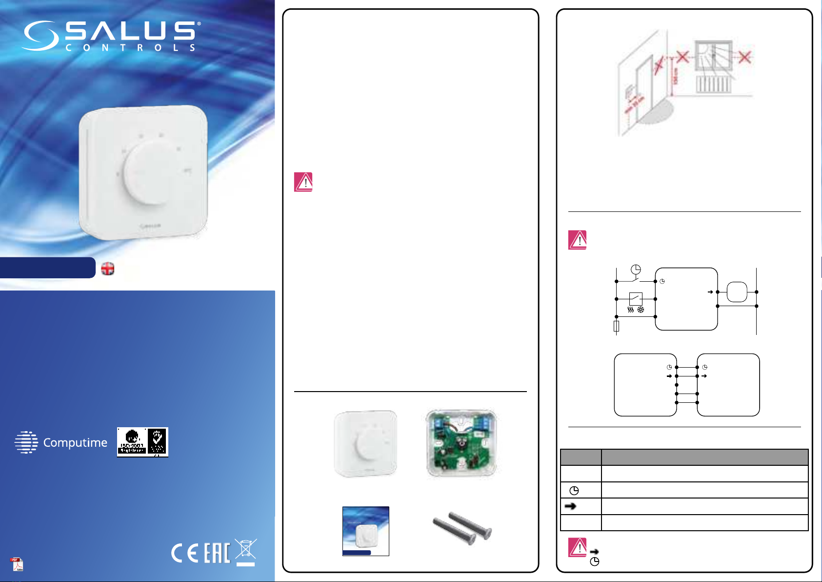
The ideal position to thermostat mounting is about 1,5m under oor level
far from heating or cooling sources. In addition, the thermostat should not be
installed behind curtains or other obstacles or in places with high humidity, as
this will prevent accurate measurements of room temperature. The thermostat
must not be exposed to sunlight. Do not place the thermostat on an outer wall.
The product complies with the following EU directives: 2014/30/EU,
2014/35/EU, 2011/65/EU. Full information is available at www.saluslegal.com
This document is a quick guide to the installation and operation of the product
and indicates its main features and functions. Detailed information is available
in the full manual, which is available at www.salus-controls.eu and must be
used for proper installation and operation of the product.
SAFETY INFORMATIONS:
Use in accordance with national and EU regulations. Use the device as intended
and keep it dry. Product for indoor use only. Please read the entire manual
before starting the installation and using the product.
INSTALLATION:
Installation must be carried out by a qualied person, with appropriate
electrical authorisations, in accordance with national and EU standards and
regulations. The manufacturer shall not be liable for failure to comply with the
manual.
NOTE:
There may be additional protection requirements for the entire installation.
Theinstaller shall be responsible for compliance with such requirements.
Front housing
of the thermostat
User manual
Back housing
of the thermostat
Mounting screws
HTR 24V KL06 24V
H (L1)
N (L2)
CO
L1
L2
Wiring centre
HTR 24V
H (L1)
N (L2)
CO
L1
AC 24V
L2
T30NC
Wejście NSB
/
NSB input
Actuator
Symbols explanation:
Wired electronic thermostat - non-programmable
Model: HTR24(20)
Wired electronic thermostat - non-pro-
grammable
Model: HTR24(20)
User manual
User manual
IMPORTER:
QL CONTROLS Sp. z o.o. Sp. k.
ul. Rolna 4, 43-262 Kobielice
PRODUCER:
Salus Limited
6/F, Building 20E, Phase 3, Hong Kong Science
Park, 20 Science Park East Avenue, Shatin,
New Territories, Hong Kong
www.salus-controls.eu
SALUS Controls is a member of the Computime Group.
In accordance with the product development policy, SALUS Controls plc reserves
the right to change specifications, design, and materials used in production,
presented in this manual, without prior notice.
Ver. 2
Date of issue: 17 III 2021
Power supply: 24V
Note:The thermostat is compatibile with the following Salus wiring
centre models: KL06 24V, KL08NSB 24V, KL04NSB 24V or directly to the
actuator.
Terminal Description
L1, L2 Power supply (24V AC)
NSB Night temperature reduction (24V input)
SL 24 V AC output signal
CO Switching jumper between heating and cooling (input 24V AC)
III 2021 [ENG]
Night setback – NSB function
The NSB (Night Set Back) function enables automatic reduction of the
temperature setpoint on the daily thermostats, via the programmable
thermostat connected to the wiring centre. The temperature change takes
place between day and night temperatures.When the night mode is activated,
the programmable thermostat sends a voltage signal to the daily thermostats
via the wiring centre. Then, the HTR24(20) thermostat automatically reduces
the temperature setpoint on the knob by 2° or 4° (as set on the SETBACK
jumper). In heating mode, the temperature is lowered when 24 V AC voltage
appears at the NSB input.
Note: For the proper NSB function work, an appropriate cable
connection is required. The connection description is on the previous
page.
Technical informations
Operation algorithm selection
The thermostat gives a possibility to choose the mode of controlling the room
temperature by PWM algorithm (default) or hysteresis +/-0.5°C. The PWM
algorithm is designed for underoor heating (for heating systems with high
inertia) – to precisely maintain the room temperature.
Set the jumper to ON – to enable or OFF – to disable the
function. This function activates the thermostatic valve for 5 minutes once a
week to prevent valve against stuck (caused by limescale).
Selecting the heating or cooling mode
Cooling blocking function.
Cooling on: Set the jumper to ON . The thermostat will work in cooling
mode if 24V AC will appear at the CO terminal.The LED lights up blue when the
thermostat sends a signal for cooling.
4
Power supply 24V AC 50Hz
Max. load TRIAC 0.5 A
Output signal 24V AC 50Hz
Temperature control range 5 – 30°C
Control method PWM or
Hysteresis: ±0.5°C
Communication Wired
Dimension [mm] 85 x 85 x 30
Jumpers for additional settings
Valve Protection
The functions of the HTR24(20) thermostat can be switched on and o by
jumpers. Please refer to the table below:
Jumpers 1 to 5 correspond to the number of actuators connected. This jumper
is factory set to position 1, which means that the thermostat controls one
actuator. Depending on the number of actuators used, the jumper position
must be changed to ensure optimal operation of the temperature thermostat.
Montage
1 2
3
Make sure that the thermostat is not connected to the 24V AC. Remove the
knob by pulling it towards you, and then open the front cover as shown in the
gure above.
Connect the thermostat. Please refer to “Connection Description” section.
Mount the thermostat using the designed screw holes.
Fold front and back housing of thermostat. The thermostat is congured.
Use the knob to set the temperature setpoint.
Jumper Function ON OFF
CO Heating / Cooling mode
– NSB Temperature reduction value
in NSB mode
PWM PWM algorithm
VP Valve Protection
2°C 4°C
Heating or cooling mode is based on the voltage sent to the CO terminal.
0V AC at the CO terminal – the thermostat is in heating mode. 24V AC at the CO
contact – the thermostat is in cooling mode.

This manual suits for next models

1

Other Salus Thermostat manuals

Salus RT310i User manual

Salus

Salus RT310i User manual

Salus iT500 User manual

Salus

Salus iT500 User manual

Salus VS20WRF User manual

Salus

Salus VS20WRF User manual

Salus Quantum SQ610 User manual

Salus

Salus Quantum SQ610 User manual

Salus STP1 User manual

Salus

Salus STP1 User manual

Salus HTR-RF(20) User manual

Salus

Salus HTR-RF(20) User manual

Salus 091FLRF User manual

Salus

Salus 091FLRF User manual

Salus CT100 User manual

Salus

Salus CT100 User manual

Salus ERT50 User manual

Salus

Salus ERT50 User manual

Salus HTRP24 User manual

Salus

Salus HTRP24 User manual

Salus ERT20RF User manual

Salus

Salus ERT20RF User manual

Salus HTR24 User guide

Salus

Salus HTR24 User guide

Salus CE-HTR230 User guide

Salus

Salus CE-HTR230 User guide

Salus ERT30RT User manual

Salus

Salus ERT30RT User manual

Salus VS20 User manual

Salus

Salus VS20 User manual

Salus RT310SPE User manual

Salus

Salus RT310SPE User manual

Salus HTRP-RF(50) User manual

Salus

Salus HTRP-RF(50) User manual

Salus iT500 User manual

Salus

Salus iT500 User manual

Salus OPTIMA ZigBee User manual

Salus

Salus OPTIMA ZigBee User manual

Salus ST625TX User manual

Salus

Salus ST625TX User manual

Salus TS600 User manual

Salus

Salus TS600 User manual

Salus RT200 User manual

Salus

Salus RT200 User manual

Salus ERT20RF User manual

Salus

Salus ERT20RF User manual

Salus VS35W User manual

Salus

Salus VS35W User manual

Popular Thermostat manuals by other brands

Flash THERMOFLASH DIGI 2 Eco quick start guide

Flash

Flash THERMOFLASH DIGI 2 Eco quick start guide

Watts 148WM installation manual

Watts

Watts 148WM installation manual

Hunter Energy Monitor 44408 installation manual

Hunter

Hunter Energy Monitor 44408 installation manual

Black & Decker BDXCTSH1 Installation & operation manual

Black & Decker

Black & Decker BDXCTSH1 Installation & operation manual

Trane BAC-1000 user guide

Trane

Trane BAC-1000 user guide

Sabiana 9060134 instruction manual

Sabiana

Sabiana 9060134 instruction manual

Tekmar tekmarNet 532 Quick setup guide

Tekmar

Tekmar tekmarNet 532 Quick setup guide

Pelican TC4 installation guide

Pelican

Pelican TC4 installation guide

White Rodgers EMERSON BLUE 1F98EZ-1421 Homeowner user guide

White Rodgers

White Rodgers EMERSON BLUE 1F98EZ-1421 Homeowner user guide

Aube Technologies TH144 Installation instructions and user guide

Aube Technologies

Aube Technologies TH144 Installation instructions and user guide

Mi-Heat Heizsysteme WT8 manual

Mi-Heat Heizsysteme

Mi-Heat Heizsysteme WT8 manual

Carrier Performance TP-PAC Product data

Carrier

Carrier Performance TP-PAC Product data

Horstmann CentaurPlus C21 User operating instructions

Horstmann

Horstmann CentaurPlus C21 User operating instructions

Honeywell Digital Round T8775A Product data

Honeywell

Honeywell Digital Round T8775A Product data

COLDBUSTER FLOORHEATING CB Smart2 instructions

COLDBUSTER FLOORHEATING

COLDBUSTER FLOORHEATING CB Smart2 instructions

Airxcel 9430 Series Installation, operation & application guide

Airxcel

Airxcel 9430 Series Installation, operation & application guide

2HEAT RF-OPTIMA quick start guide

2HEAT

2HEAT RF-OPTIMA quick start guide

thermotouch 4.3dC Installation & user guide

thermotouch

thermotouch 4.3dC Installation & user guide

manuals.online logo
manuals.online logoBrands
  • About & Mission
  • Contact us
  • Privacy Policy
  • Terms and Conditions

Copyright 2025 Manuals.Online. All Rights Reserved.