manuals.online logo
Brands
  1. Home
  2. •
  3. Brands
  4. •
  5. SALZ
  6. •
  7. Switch
  8. •
  9. SALZ 2008GT User manual

SALZ 2008GT User manual

SWITCH 2008GT
Quick Installation Guide
-1- -2- -3-
1. Overview
SWITCH 2008GT Unmanaged Industrial Ethernet Switch is
specially designed to expand reliable Ethernet connectivity to
factory oors and outdoor environments with extreme
temperature and climatic conditions.
SWITCH 2008GT is equipped with 8 x 10/100/1000 RJ45 Ports
enclosed in IP30 housing.
4. Grounding the switch SWITCH 2008GT
!
ATTENTION:
This product is intended to be mounted to a well-
grounded mounting surface such as a metal panel.
!
WARNING:
Safety measures should be taken before connecting
the power cable.Turn o the power before connecting
modules or wires. The correct power supply voltage is listed on
the product label. Check the voltage of your power source to
make sure that you are using the correct voltage. DO NOT use a
voltage greater than what is specied on the product label.
Calculate the maximum possible current in each power wire and
common wire. Observe all electrical codes dictating the
maximum current allowable for each wire size. If current
exceeds the maximum rating, the wiring can overheat causing
serious damage to your equipment.
Please read and follow these guidelines:
• Use separate paths to route wiring for power and devices. If
power wiring and device wiring paths must cross make sure
the wires are perpendicular at the intersection point
NOTE: Do not run signal or communications wiring and power
wiring through the same wire conduit. To avoid interference,
wires with dierent signal characteristics should be routed
separately
• You can use the type of signal transmitted through a wire to
determine which wires should be kept separate. The rule of
thumb is that wiring that shares similar electrical characteris-
tics can be bundled together
• You should separate input wiring from output wiring
• We advise that you label the wiring to all devices in the system
Removing the SwitchMounting the Switch
Click
Dismounting the switch
Press the switch from top and pull out the lower edge of the
switch and then remove the switch from the DIN rail.
Mounting the switch
Place the SWITCH 2008GT on the DIN rail from above using the
slot, push the front of the switch toward the mounting surface
until it snaps into place with a click sound.
Grounding and wire routing help limit the eects of noise due to
electromagnetic interference (EMI).
Step 1: Run the ground connection from the ground screw to
the grounding surface prior to connecting devices.
Step 2: Connect the ground connection from the terminal block
to the grounding surface prior to connecting device.
5. Wiring requirements
5.1 Wiring Power Input
5.1.1 SWITCH 2008GT with 6pin terminal block
!
Caution:
• Use copper conductors only
• Wiring cable temperature should support at
least 105˚C
• Tighten the wire to a torque value 20N
• The wire gauge for the terminal block should
range between 0.2 to 2.5 mm2
-
2. Package Checklist
• SWITCH 2008GT Switch x 1
3. Mounting and Dismounting to DIN-Rail
!ATTENTION:
The SWITCH 2008GT ia an open type device and
SWITCH 2008GT shall be DIN-Rail mounted in cabinet
or enclosure and the ambient temperature should not
exceed 75 °C.
Panel view
Top View
DIP Switches
DIN-Rail
Grounding
Screw
Power Input
Terminal Block
+
PWR
+
RPS
ALM
9~57VDC
OFF
1
2
ON
3
4
5
6
7
8
9
10
1 PWR
ALM
P1
P2
P3
P4
P5
P6
P7
P8
RPS2
3
4
5
6
7
8
9
10
Front View
7
5
3
8
6
4
1000Mbps
LNK/ACT
1 2
PWR
RPS
ALM
PWR
RPS
ALM
1000M
LNK/ACT
Grounding Screw
You can use “PWR” for Primary Power input and “RPS” for
Redundant Power Input.
Top view of Terminal Block is shown in the gure below:
Terminal Block
-4- -5- -6-
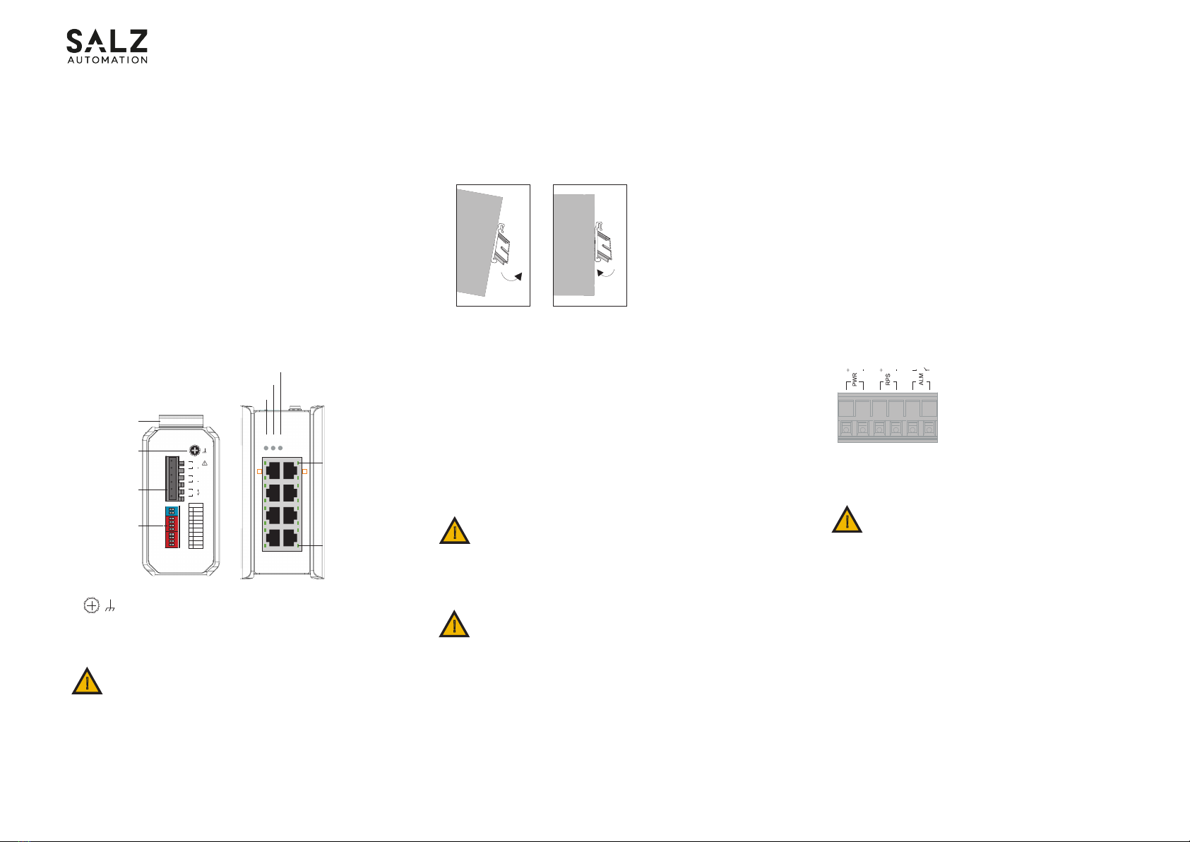
To insert power wire and connect the 9 to 57 V DC at a
maximum of 1 A DC power to the power terminal block, follow
the steps below:
• Use at-head screw driver to loosen the wire-clamp screws
• Insert the negative/positive DC wires into the PWR-/PWR+
terminals, respectively
• Tighten the wire-clamp screws to prevent the wires from loosen-
ing
!ATTENTION:
Please use a power supply from 9 to 57 V DC, the
device power shall be supplied by SELV circuit.
!ATTENTION:
This device complies with Part 15 of the FCC rules.
Operation is subject to the following conditions:
1. This device may not cause harmful interference
2. This device must accept any interference received
including interference that may cause undesired
operation
!ATTENTION:
If the equipment is used in a manner not specied by
SALZ Automation, the protection provided by the
equipment may be impaired.
Connect one end of an Ethernet/RJ45 cable into Ethernet port
of SWITCH 2008GT and other end to attached networking
device.
• Ports 1-8 of the switch support Fast Ethernet as well as
Gigabit Ethernet (10/100/1000Base-T RJ45 Ports)
• All the RJ45 ports on the SWITCH 2008GT support auto
negotiation and auto MDI/MDI-X to eliminate the need for
crossover cabling
5.3 Cabling RJ45
Address of the manufacturer:
SALZ Automation GmbH
Max-Planck-Str. 64
32107 Bad Salzuen, Germany
Email: [email protected]
Please scan for more information:
v0.2
Note: Category 5e cable or above should be used.
Operating Temperature
-40˚C ... 75˚C
Storage Temperature
-40˚C ... 80˚C
Altitude
Up to 2000m
Ambient relative humidity
10 to 95% (non-condensing)
UL61010
Indoor use and pollution degree 2
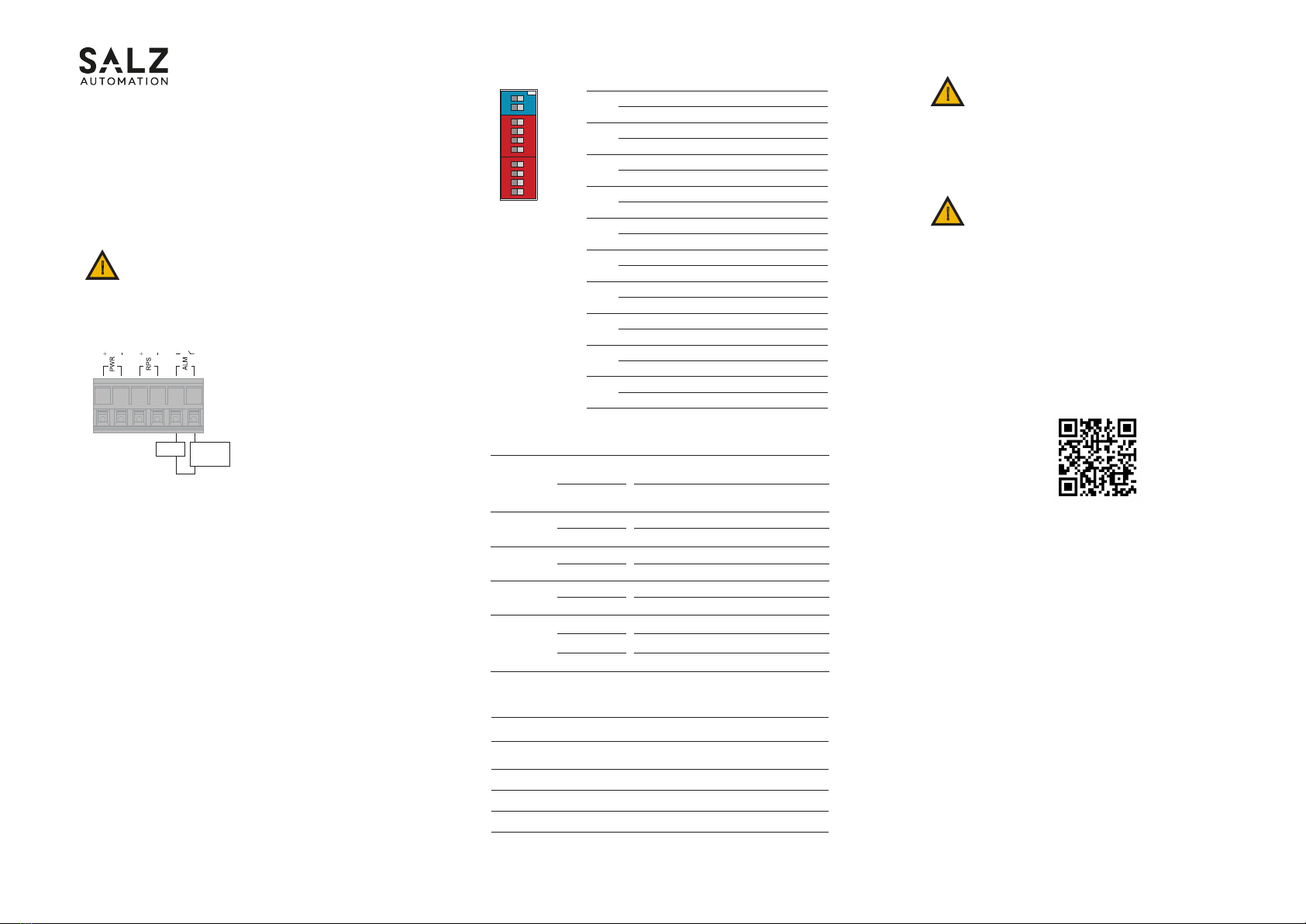
ON
1 2 1 2 3 4 1 2 3 4
PWR
RPS
P1
P2
P3
P4
P5
P6
P7
P8
1
2
3
4
5
6
7
8
9
10
6. DIP Switch Setting
8. Environmental limits
7. LED Indicators
PWR
(Green)
Power On by terminal block PWR or
DC-Jack
Terminal block PWR/DC-Jack fails or
is not available
RPS
(Green)
Power On by terminal block RPS
Terminal block RPS fails or is not available
PWR/RPS fails or not available
No power lost or DIP function is disabled
LNK/ACT
(Green)
Copper port link-up 1000Mbps
Data is transmitting / receiving
Port disconnected or link failed
Illuminated
Illuminated
Illuminated
ALM
(Red)
1000M
(Green)
O
O
O
Illuminated
O
Illuminated
Blinking
O
Link speed at 10/100Mbps
Link speed at 1000Mbps
PWR
ON
: Primary power alarm reporting is enabled
OFF : Primary power alarm reporting is disabled
RPS
ON
: Redundant power alarm reporting is enabled
OFF : Redundant power alarm reporting is disabled
P1
ON
: Port 1 link alarm reporting is enabled
OFF : Port 1 link alarm reporting is disabled
P2
ON
: Port 2 link alarm reporting is enabled
OFF : Port 2 link alarm reporting is disabled
P3
ON
: Port 3 link alarm reporting is enabled
OFF : Port 3 link alarm reporting is disabled
P4
ON
: Port 4 link alarm reporting is enabled
OFF : Port 4 link alarm reporting is disabled
P5
ON
: Port 5 link alarm reporting is enabled
OFF : Port 5 link alarm reporting is disabled
P6
ON
: Port 6 link alarm reporting is enabled
OFF : Port 6 link alarm reporting is disabled
P7
ON
: Port 7 link alarm reporting is enabled
OFF : Port 7 link alarm reporting is disabled
P8
ON
: Port 8 link alarm reporting is enabled
OFF : Port 8 link alarm reporting is disabled
Load External
Power
The SWITCH 2008GT has one set of relay alarm output. This
relay contact uses two contacts of the terminal block on the
top panel.
The two contacts of the 6-pin terminal block connector are
used to detect user-congured events. The two wires attached
to the fault contacts form an open circuit when a user-cong-
ured event is triggered. If a user-congured event does not
occur, the fault circuit remains closed.
Relay rating: 24V, 1A
5.2 Wiring the relay contact (ALM)

Other SALZ Switch manuals

SALZ SWITCH 2008TX User manual

SALZ

SALZ SWITCH 2008TX User manual

SALZ 2005TX User manual

SALZ

SALZ 2005TX User manual

SALZ SWITCH 4008GT User manual

SALZ

SALZ SWITCH 4008GT User manual

SALZ 2016GT-E User manual

SALZ

SALZ 2016GT-E User manual

SALZ 2016GT User manual

SALZ

SALZ 2016GT User manual

SALZ 4008GT User manual

SALZ

SALZ 4008GT User manual

SALZ 2005GT User manual

SALZ

SALZ 2005GT User manual

Popular Switch manuals by other brands

B&B Electronics ETHUB16 datasheet

B&B Electronics

B&B Electronics ETHUB16 datasheet

ABB Zenith ZTG Series quick start guide

ABB

ABB Zenith ZTG Series quick start guide

Extreme Networks ExtremeSwitching 210-12t-GE2 Hardware installation guide

Extreme Networks

Extreme Networks ExtremeSwitching 210-12t-GE2 Hardware installation guide

AvLab AceProAv user manual

AvLab

AvLab AceProAv user manual

Krom Schroder DG**H series operating instructions

Krom Schroder

Krom Schroder DG**H series operating instructions

Manhattan IDATA HDMI-218K instructions

Manhattan

Manhattan IDATA HDMI-218K instructions

Raritan Dominion KX II user guide

Raritan

Raritan Dominion KX II user guide

SignaMax 065-7890FSFPDP quick start guide

SignaMax

SignaMax 065-7890FSFPDP quick start guide

Crestron DM-MD8X1-4K-C Do guide

Crestron

Crestron DM-MD8X1-4K-C Do guide

Uplift Desk PDC007 quick start guide

Uplift Desk

Uplift Desk PDC007 quick start guide

Leonton BG5-0702-SFP-24 Series user manual

Leonton

Leonton BG5-0702-SFP-24 Series user manual

Cisco CDB-8U installation guide

Cisco

Cisco CDB-8U installation guide

Fujitsu PSWITCH 2048T user guide

Fujitsu

Fujitsu PSWITCH 2048T user guide

UE ONE Series Installation and maintenance instructions

UE

UE ONE Series Installation and maintenance instructions

BHI 1042 operating instructions

BHI

BHI 1042 operating instructions

WOODLAND SCENICS Just Plug JP5680 user manual

WOODLAND SCENICS

WOODLAND SCENICS Just Plug JP5680 user manual

THOMSON TS 870 Installation, operating & service manual

THOMSON

THOMSON TS 870 Installation, operating & service manual

axing basic-line SPU 94-05 Operation instructions

axing

axing basic-line SPU 94-05 Operation instructions

manuals.online logo
manuals.online logoBrands
  • About & Mission
  • Contact us
  • Privacy Policy
  • Terms and Conditions

Copyright 2025 Manuals.Online. All Rights Reserved.