-1-
-2-
-3-
The SWITCH 4008GT Lite-Managed Industrial Ethernet Switch and includes 8-port
10/100/1000Mbps RJ45 downlink ports.
Connect through Web Browser:
• Connect your computer to one of the Ethernet ports.
• Use the default IP-address 192.168.0.254 to login to the switch.
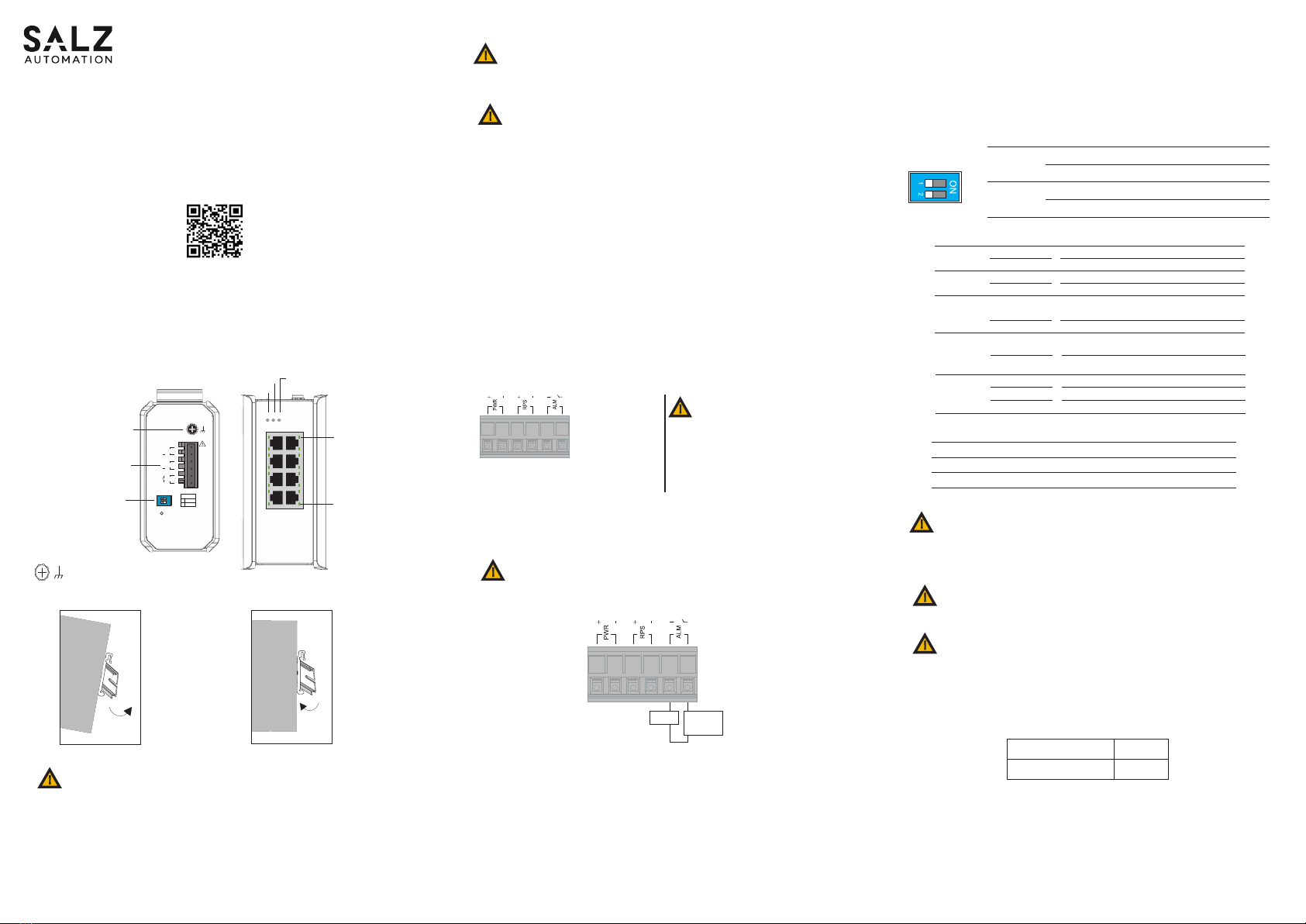
9. Conguration
Default Username
Default Password
SALZ
admin
NOTE: For more details on conguration please refer user manual.
6. DIP Switch Setting
Illuminated
O
PWR
(Green)
Primary power on
Primary power o or failure
Illuminated
O
RPS
(Green)
Redundant power on
Redundant power o or failure
Illuminated
O
ALM
(Red)
Alarm triggered for abnormal power status
and anomalous features.
Normal operation or DIP switch OFF
-40°C ... 75°C (-40°F ... 167°F)
-40°C ... 85°C (-40°F ... 185°F)
5 to 95% (non condensing)
Operating Temperature
Storage Temperature
Ambient relative humidity
ATTENTION:
If the equipment is used in a manner not specied by the SALZ
Automation GmbH, the protection provided by the equipment may be
impaired.
ATTENTION:
Please leave at least 5cm of space at the left and right of the unit for
ventilation.
1
PWR ON: Primary power alarm reporting is enabled
OFF: Primary power alarm reporting is disabled
2
RPS ON: Redundant power alarm reporting is enabled
OFF: Redundant power alarm reporting is disabled
OFF ON
1
2
1000
(Green)
(1~8
th
RJ45 port)
Illuminated
O
Link speed at 1000Mbps
Link speed at 10/100Mbps
LNK/ACT
(Green)
(1~8
th
RJ45 port)
Port link-up
Activity (receiving or transmitting data)
Port disconnected or link failed
Illuminated
Blinking
O
Top View
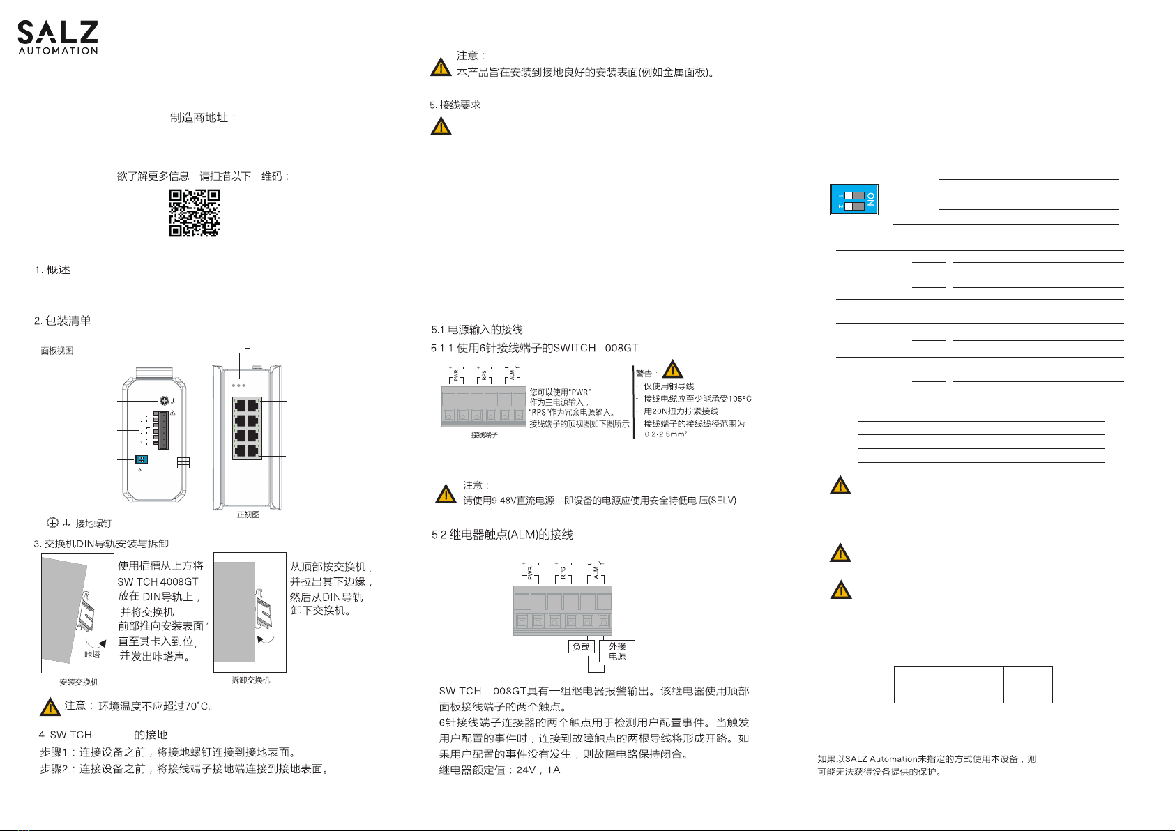
Grounding
Screw
Power Input
Terminal Block
DIP Switches
Reset
24~48VDC
PWR
+
+
RPS
ALM
OFF
1
2
ON
1 PWR
ALM
RPS2
LNK/
ACT
1000
1
3
5
7
2
4
6
8
1000Mbps
(Green)
LNK/ACT
(Green)
Grounding Screw
1. Overview
2. Package Checklist
• SWITCH 4008GT Switch x 1
Panel view
Address of the manufacturer:
SALZ Automation GmbH
Max-Planck-Str. 64
32107 Bad Salzuen, Germany
Please scan for more information:
Removing the Switch
Mounting the Switch
Click
Press the
switch from
top and pull
out the
lower edge
of the switch
and then
remove the
switch from
the DIN rail.
Place the SWITCH
2008GT on the DIN
rail from above
using the slot, push
the front of the
switch toward the
mounting surface
until it snaps into
place with a click
sound.
3. Mounting and Dismounting to DIN-Rail
!
ATTENTION: Ambient temperature should not exceed 70°C.
4. Grounding the switch SWITCH 4008GT
Step1: Run the ground connection from the ground screw to
the grounding surface prior to connecting devices.
Step2: Connect the ground connection from the terminal block
to the grounding surface prior to connecting device.
SWITCH 4008GT
Quick Installation Guide
Front View
You can use “PWR”
for Primary Power
input and “RPS” for
Redundant Power
Input.
Terminal Block
Load External
Power
The SWITCH 4008GT has one set of relay alarm output. This relay contact uses two
contacts of the terminal block on the top panel.
The two contacts of the 6-pin terminal block connector are used to detect user-cong-
ured events. The two wires attached to the fault contacts form an open circuit when a
user-congured event is triggered. If a user-congured event does not occur, the fault
circuit remains closed.
Relay rating: 24V, 1A
5.2 Wiring the relay contact (ALM)
WARNING:
Turn o the power before connecting modules or wires. The correct power supply
voltage is listed on the product label. Check the voltage of your power source to
make sure that you are using the correct voltage. DO NOT use a voltage greater than
what is specied on the product label. Calculate the maximum possible current in each
power wire and common wire. Observe all electrical codes dictating the maximum
current allowable for each wire size. If current exceeds the maximum rating, the wiring
can overheat causing serious damage to your equipment.
• Use separate paths to route wiring for power and devices. If power wiring and device
wiring paths must cross make sure the wires are perpendicular at the intersection
point.
NOTE: Do not run signal or communications wiring and power wiring through
the same wire conduit. To avoid interference, wires with dierent signal
characteristics should be routed separately.
5. Wiring requirements
!
ATTENTION: To be mounted on a well- grounded mounting surface such as a
metal panel.
!
• You can use the type of signal transmitted through a wire to determine which wires
should be kept separate. The rule of thumb is that wiring that shares similar electrical
characteristics can be bundled together.
• You should separate input wiring from output wiring.
• We advise that you label the wiring to all devices in the system.
5.1 Wiring Power Input
5.1.1 SWITCH 4008GT with 6pin terminal block
Caution:
• Use copper conductors only
• Wiring cable temperature should
support at least 105˚C
• Tighten the wire to a torque value
20N
• The wire gauge for the terminal
block should range between 0.2 to
2.5 mm2
!
To insert power wire and connect the 9 to 48 V DC at a maximum of 0.5 A DC power to
the power terminal block, Loosen the wire-clamp screws, Insert the negative/positive
DC wires into the ( - /+) terminals, respectively, and Tighten the wire-clamp screws.
!
ATTENTION: Please use a power supply from 9 to 48 V DC, the device power
shall be supplied by SELV circuit.
Connect one end of an Ethernet/RJ45 cable into Ethernet port of SWITCH 4008GT and
other end to attached networking device. Ports 1-8 of the switch support fast Ethernet
and Gbit Ethernet (10/100/1000Base-T RJ45 Ports) All the RJ45 ports on the SWITCH
4008GT support auto negotiation and auto MDI/MDI-X to eliminate the need for
crossover cabling. Note: Category 5e cable or above should be used.
5.3 Cabling RJ45
7. LED Indicators
8. Environmental limits
ATTENTION:
This device complies with Part 15 of the FCC rules. Operation is subject to
the following conditions:
1. This device may not cause harmful interference.
2. This device must accept any interference received including interference
that may cause undesired operation.
If the equipment is used in a manner not specied by SALZ Automation, the
protection provided by the equipment may be impaired.
!
!
!
PWR
RPS ALM
PWR
RPS
ALM