NVT NV-8PS42-PVD User manual

Pow r Supply StubEQTM R c iv r Hub Installation Guid
Mod ls NV-8PS42-PVD, NV-16PS42-PVD and NV-32PS42-PVD
1) Re d these instructions.
2) Keep these instructions.
3) Heed ll w rnings.
4) Follow ll instructions.
5) Do not use this pp r tus ne r w ter.
6) Cle n only with dry cloth.
7) Do not block ny ventil tion openings.
8) Inst ll in ccord nce with the m nuf cturer’s instructions.
9) Do not inst ll ne r ny he t sources such s r di tors, he t
registers, stoves or other pp r tus (including DVRs) th t
produce he t.
10) Do not defe t the s fety purpose of the pol rized or
grounding-type plug. A pol rized plug h s two bl des with
one wider th n the other. A grounding type plug h s two
bl des nd third grounding prong. The wider bl de or the
third prong re provided for your s fety. If the provided plug
does not fit into your outlet, consult n electrici n for
repl cement of the obsolete outlet.
11) Protect the power cord from being w lked on or pinched
p rticul rly t plugs, convenience recept cles, nd the point
where they exit from the pp r tus.
12) Only use tt chments/ ccessories specified by the
m nuf cturer.
13) Use only with c rt, st nd, tripod, br cket, or t ble
specified by the m nuf cturer, or sold with the pp r tus.
When c rt is used, use c ution when moving the
c rt/ pp r tus combin tion to void injury from tipover.
14) Unplug this pp r tus during lightning storms or when
unused for long periods of time.
15) Refer ll servicing to qu lified service personnel.
Servicing is required when the pp r tus h s been d m ged
in ny w y, such s power supply cord or plug is d m ged,
liquid h s been spilled, or objects h ve f llen into the
pp r tus, the pp r tus h s been exposed to r in or
moisture, does not oper te norm lly, or h s been dropped.
This installation should be made by a qualified
service person and should conform to all local codes.
WARNING - Do not install the unit in an environment
where the operating ambient temperature exceeds 122° F
(50° C). The ventilation should not be impeded by
covering the ventilation openings with items, such as
newspapers, table-cloths, curtains, etc. No naked flame
sources, such as lighted candles should be placed on the
apparatus.
WARNING - Do not interconnect multiple
outputs.
WARNING - The apparatus shall not be exposed to
dripping or splashing and no objects filled with liquids,
such as vases, shall be placed on the apparatus.
WARNING - Use only a Certified power cord and plug
(coupler / mains) assemblies for location installed.
WARNING - Power cord is regarded as main
disconnect.
WARNING - Class 1 apparatus shall be connected to
a mains socket outlet with a protective earthing
connection.
WARNING - The appliance coupler (power
cord/mains) shall remain readily operable.
WARNING - For safety, never put NVT signals in the
same conduit as high-voltage wiring.
WARNING - Do not restrict airflow around any active
powered NVT products. Model NV-32P 42-PVD requires a
minimum of 2.5 in. (63.5mm) unrestricted open air space
on each side of the unit.
TO REDUCE THE RI K OF ELECTRICAL HOCK, DO NOT
REMOVE COVER OR BACK. NO U ER ERVICEABLE
PART IN IDE. REFER ERVICING TO QUALIFIED
ERVICE PER ONNEL.
WARNING: TO REDUCE THE RI K OF ELECTRICAL
HOCK, DO NOT EXPO E THI APPARATU TO RAIN OR
MOI TURE.
IMPORTANT AFETY IN TRUCTION
NV-8PS42-PVD, NV-16PS42-PVD
or NV-32PS42-PVD
Camera Location and
Transmitter Connections
IDF | MDF | Control Room
and Receiver Connections IP
NV-216A-PV
NV-218A-PVD
Camera
The NVT Power Supply StubEQ™ Receiver ub is an active
(amplified) hub that allows the transmission of real-time
monochrome or color video for distances up to 1,500ft (460m)
using Cat5 or better unshielded twisted-pair (UTP) wire. Its
2-band equalizer continuously and automatically compensates
for cable attenuation and ground loops, independent of the video
content. The 1U hub is equipped with multi-stage transient
protection.
The hub combines a 28VAC power supply with video and
telemetry data, for 8 to 32 cameras, all over UTP wire. Designed
for installation in the Control/MDF room, the hub consolidates
connectivity via standard 4-pair RJ45 EIA/TIA 568B compliant
premises wiring and pinouts.
At the camera, power, video, and data connections are made
using the NV-216A-PV or NV-226J-PV (power & video only) or
the NV-218A-PVD (power, video, and telemetry data) transceiver
via an RJ45 connector and a single 4-pair cable. Control/MDF
connections are also RJ45, with BNC video outputs for the DVR,
matrix switcher, etc. Telemetry connections, if required, are
supported via an RJ45 connector for each group of four camera
channels.
The NV-8PS42 supports up to 8 cameras at up to 1 amp per
camera, and delivers two BNC outputs per channel. The
NV-16PS42 supports up to 16 cameras at up to 1 amp per
camera, and delivers two BNC outputs per channel. The NV-
32PS42 supports up to 32 cameras at up to 500mA per camera,
and delivers one BNC output per channel.
Wir Typ
The Power Supply StubEQTM Receiver operates well with Category 5 or
better Unshielded Twisted-Pair (UTP) wire, 24-22 AWG (0,5-0,64mm).
The video signal may co-exist in the same cable tray as other
video, telephone, data, control signals, or low-voltage power. It is
also OK to run NVT signals near electromagnetic fields (in
accordance with National Electrical Code, and other local safety
requirements).
DO NOT USE individually shielded twisted pair. Overall shielded,
multi-pair (6pr +) Cat5 is OK.
Do NOT use un-twisted wire.
Wire in underground conduit or wet locations must be
polyethelyne-jacketed, gel-filled.
Wire in plenum environments must be plenum-rated, per local
codes.
RS-422 and RS-485 Pan/Tilt/Zoom telemetry signals are
supported.
Wir Distanc
All measured distances include any coax in the path.
Wire resistance may be measured with an ohm-meter by shorting
the two conductors together at the far end, and measuring the
loop-resistance out and back. 1000 feet (300m) of 24 AWG
(0.53mm) wire is 52 ohms; 23 AWG (0.57mm) is 42 ohms.
Wire distances are limited to the minimum of:
POWER DISTANCE - the power loss along the wire from the
Power Supply Passive Receiver Hub out to the camera,
- or the -
IDEO DISTANCE - the video signal distance limit from camera to
the Power Supply StubEQTM Receiver, not to exceed 1500ft (460m).
Conn cting PVD at th Cam ra End
Use the NV-216A-PV for fixed cameras, or the NV-218A-PVD for
fixed or P/T/Z cameras. Install per the instructions that come with
the transmitting device using 4-pair wire and RJ45 connectors.
NVT recommends the use of factory-crimped RJ45 patch cables
rather than unreliable field-crimped RJ45s to connect between the
NVT device and an adjacent female RJ45 jack. Wiring pinouts are:
Conn cting PVD at th Pow r Supply
StubEQTM R c iv r Hub
CAUTION: Before applying power set voltage selection
switch to proper input line voltage.
Bring the 4-pair PVD cable from each camera back to the location
of the Power Supply StubEQTM Receiver. NVT recommends that an
RJ45 Patch Panel be used here in conjunction with RJ45 patch-
cords. Use of these EIA/TIA 568B compliant practices allows for
easy testing with an RJ45 (LAN) tester, as well as moves and
changes.
Connect the PVD signals into ports on the front of the Power Supply
StubEQTM Receiver ub.
Connect the IEC cable between the power inlet and a grounded
electrical outlet. Switch on the power switch and observe the blue
power LED.
Vid o Distanc
Recommended wire distances for best resolution is shown in
chart below. Wire distance between the camera and the Power
Supply StubEQTM Receiver ub should not exceed these
recommendations:
Pow r Distanc
Wire distance between the Power Supply StubEQTM Receiver ub
and the camera is dependent on the camera’s current draw. Please
refer to the Power Distance Charts below.
1
2
3
4
5
6
7
8
Wht/org
Org/wht
Wht/grn
Blu/wht
Wht/blu
Grn/wht
Wht/brn
Brn/wht
Video +
Video
-
Data +
Power
-
Power +
Data
-
Power +
Power
-
Cat 5 Wire Distance
Cat 5 Wire Distance
235
315
400
475
550
630
700
780
3 MHz
4 MHz
5 MHz
6 MHz
9MHz
8MHz
7MHz
10 MHz
100ft
Camera Lines of Resolution
Frequency
300ft
1,000ft
1 mile
3,000ft
10,000ft
30m
100m
300m
1,6km
1km
3km
M
a
x
P
a
s
s
i
v
e
D
i
s
t
a
n
c
e
M
a
x
S
t
u
b
E
Q
D
i
s
t
a
n
c
e
M
a
x
D
i
g
i
t
a
l
E
Q
D
i
s
t
a
n
c
e
Fixed Camera 24VAC only, used with NV-216A-PV
Power Supply Voltage
Minimum Voltage at Camera
789ft (240m)
994ft (303m)
393ft (120m)
495ft (151m)
262ft (80m)
331ft (101m)
1,840ft (561m)
2,320ft (707m)
916ft (279m)
1,155ft (352m)
612ft (186m)
771ft (235m)
B&W Camera, 2.4 W
2-pair 24 AWG
2-pair 23 AWG
Color Camera, 4.8 W
2-pair 24 AWG
2-pair 23 AWG
Color Camera, 7.2 W
2-pair 24 AWG
2-pair 23 AWG
24 VAC
21 VAC
28 VAC
21 VAC
P/T/Z 24VAC Camera used with NV-218A-PVD
Power Supply Voltage
Minimum Voltage at Camera
90ft (27m)
113ft (35m)
210ft (64m)
265ft (81m)
P/T/Z Camera, 21 W
2-pair 24 AWG
2-pair 23 AWG
24 VAC
21 VAC
28 VAC
21 VAC
Fixed Dual Voltage 24VAC/12VDC Camera with NV-216A-PV
Power Supply Voltage
Minimum Voltage at Camera
1,753ft (534m)
2,210ft (674m)
874ft (266m)
1,102ft (336m)
583ft (178m)
735ft (224m)
2,454ft (748m)
3,094ft (943m)
1,223ft (373m)
1,542ft (470m)
816ft (249m)
1,029ft (314m)
B&W Camera, 2.4 W
2-pair 24 AWG
2-pair 23 AWG
Color Camera, 4.8 W
2-pair 24 AWG
2-pair 23 AWG
Color Camera, 7.2 W
2-pair 24 AWG
2-pair 23 AWG
24 VAC
14 VAC
28 VAC
14 VAC

Chann l LED Indicators
Each RJ45 connector has two LEDs. The LEFT LED indicates
video status:
OFF: No video received
SOLID GREEN: Video received and equalized
WINKING GREEN: Video present, but cannot equalize
typically due to wire that is too long
RED: Time varying signal detected,
but it’s not video
The RIG T LED indicates 28VAC Power status:
OFF: No camera current (<50 mA)
SOLID GREEN: Camera current detected
WINKING GREEN: Current in the four power
conductors don’t match
one of the four power
conductors is open
Detects that current in each of the four power conductors is the
same, allowing for the detection of open conductors. Above 100
feet, or with high current P/T/Z cameras, the winking green LED
is an indication that the wire continuity should be checked with
a ohm meter or LAN tester for miswires.
ALTERNATING
RED/GREEN: Current exceeds ub’s spec
RED: Thermistor protector has opened due to
over-current fault check for shorts in
the wiring
FAST FLAS ING RED: CAUTION: AZARDOUS VOLTAGE
DETECTED
Conn cting th Vid o Outputs
Using the BNC jumper cables (included) connect the video
outputs on the rear of the Power Supply StubEQTM Receiver ub
to the DVR, encoder, or multiplexer.
The NV-8PS42-PVD supports 8 channels, two BNC outputs each
The NV-16PS42-PVD supports 16 channels, two BNC outputs each
The NV-32PS42-PVD supports 32 channels, single BNC output
Data Conn ctions
The data path for each camera arrives on the front RJ45 jack
of the Power Supply StubEQTM Receiver ub. Each Data jack
supports the pass-through of four camera data signals. Use a 4-
pair Cat5 cable to bring these data signals back to the P/T/Z
Controller. For small installations, these wire pairs may be
connected directly to the RS-422/485 telemetry control output
on your controller. In most cases a “Code Distribution Unit”
(available from the camera manufacturer) is inserted between
the telemetry output and the wire-pairs. This allows one
telemetry output to drive many cameras without having to drive
too many loads. It also prevents a fault at one camera from
taking down the entire system.
Rack / Tabl / Wall Mounting
Ambient temperature must be below 122°F (50°C). Airflow
must be at least 4ft3/min (0,13/min) of un-restricted airflow.
Many DVRs produce enough heat to exceed this temperature
without external airflow.
For 19” rack mounting, use enclosed “L” brackets and
screws. Because the NV-16PS42-PVD and the NV-32PS42-PVD
ubs weigh approximately 25 lbs. (11,3kg), some thinner-
gauge rack systems may require additional rear support. NVT
provides a rear-rail mounting accessory kit for this purpose.
For table mounting, use enclosed self adhesive rubber feet
and attach to the bottom corners of the hub.
For wall mounting, attach the optional mounting “L” brackets
to two sides of the unit, using the enclosed screws. The
brackets may be installed facing outward or inward. Inward
facing brackets allow the unit to be mounted on 16” centres,
useful in US wall stud applications. For easy connector and LED
access, it is recommended that the front of the unit faces left.
1
1
24V 28V
Power
NV-16PS10-PVD Mid-Span Power Supply Hub Network Video Te chnologies
TM
NVT
1 1
12 16
24V 28V 24V 28V
1
1
24V 28V
Power
NV-16PS10-PVD Mid-Span Power Supply Hub Network Video Te chnologies
TM
NVT
1 1
12 16
24V 28V 24V 28V
T chnical Sp cifications
ideo
Frequency DC to 10 M z
Attenuation 0.5 dB typ
Common Mode/Differential Mode Rejection
15 K z to 10 M z 60dB typ
Power Output
Output oltage 28VAC
Maximum ouput current
NV-8PS42-PVD: 1 Amp per channel, 8 aggregate
NV-16PS42-PVD: 1 Amp per channel, 16 aggregate
NV-32PS42-PVD: 0.5 Amp per channel, 16 aggregate
Connectors and Impedance
UTP input 100 ± 20 ohms
BNC output 75 ohms
LEDs
Power Blue
Channel Status see column 1
Environmental
Temperature 32 to 122°F (0 to 50°C)
umidity 0 to 95% non-condensing
Transient immunity per ANSI / IEEE687 C62.41
Power Input
IEC380 Inlet
Power Cord
IEC380 AC line power receptacle for use
with removable cords. Use only the power
cord provided with the unit or equivalent
UL approved type SJT or SVT, 18AWG,
125/250V, 5A 60 deg.C, Max. 4,5m long;
One end with NEMA 5-15P. Other end with
appliance coupler.
N -8PS42-P D
Voltage 115/230 VAC
Frequency 50/60 z
Current Wattage 2.5 A @ 115 VAC,
2.5A @ 230 VAC, 250 W
eat 250 BTU/ r (power supply only)
1,000 BTU/ r
(power supply with camera)
N -16PS42-P D
Voltage 115/230 VAC
Frequency 50/60 z
Current Wattage 5 A @ 115 VAC,
2.5 A @ 230 VAC, 500 W
eat 275 BTU/ r (power supply only)
2,000 BTU/ r
(power supply with camera)
N -32PS42-P D
Voltage 115/230 VAC
Frequency 50/60 z
Current Wattage 5 A @ 115 VAC,
2.5A @ 230 VAC, 500 W
eat 325 BTU/ r (power supply only)
2,000 BTU/ r
(power supply with camera)
Fuse 5 x 20mm Type T
NV-8PS42-PVD 5 Amps
NV-16PS42-PVD 5 Amps
NV-32PS42-PVD 5 Amps
A spare fuse is located inside the fuse holder.
Weight (Excluding brackets and connectors)
NV-8PS42-PVD Product Weight 13lb (5,90kg)
Packaged Weight 17lb. (7,7kg)
NV-16PS42-PVD Product Weight 23.5lb (10,66kg)
Packaged Weight 32lb (14,5kg)
NV-32PS42-PVD Product Weight 24.1lb (10,93kg)
Packaged Weight 40lb (18,14kg)
RoHS
Dimensions
N -8PS42-P D
W17” (43,2cm) H1.7” (4,5cm) D8in (20cm)
N -16PS42-P D
W17” (43,2cm) H1.7” (4,5cm) D12in (30cm)
N -32PS42-P D
W17” (43,2cm) H1.7” (4,5cm) D12in (30cm)
Accessories
-Mounting: Rackmount “L” brackets for front or rear
installations; rubber feet for desk applications
-Rack screws: 4 12-24 x 3/4” Phillips Pan ead
-BNC patch cables: 2ft long 1 per channel
-Power cable IEC power cord 7ft (2,13m)
-Optional Mounting Support Bracket Kits
Model NV-RMBK (rear mount kit) purchased separately
Model NV-WMBK (wallmount kit) purchased separately
Ag ncy
These NVT products are listed and/or conform
to the following certifications and directives:
UL Listed to UL2044 or UL/IEC60065 cUL
Listed to CAN/CSA22.2 No.1 for Canada CE Mark
under EMC and low voltage directives for the European Union.
Complies with FCC part 15B limits
Troubl shooting
If you are experiencing problems, attempt to simplify your
setup. Test each cable segment separately. For example, test
the camera and monitor together without the other equipment.
Then add in the NVT transceivers, back-to-back. Test each
segment of a long cable-run independently. Attempt to isolate
the problem.
Custom r Support
NVT customer support is available for consultation from 8:00
AM to 5:30 PM PST Monday through Friday. In addition,
emergency after-hours callback support is available.
USA Office: (+1) (650) 462-8100
USA Fax: (+1) (650) 326-1940
UK Office: (+44) (0)20 8977 6614
UK Fax: (+44) (0)20 8973 1855
Email USA: www.nvt.com/email
Email UK: www.nvt.com/email
Web home page: www.nvt.com
R turns
Please call before returning units to NVT. Returned materials
must have a “Returned Materials Authorization” (RMA) number
from NVT marked on the outside of the shipping carton.
Limit d Lif tim Warranty
NVT warrants that the product conforms to NVT’s applicable
published specifications and is free of defects for the life of the
product. There shall be no other warranties, express, statuatory,
or otherwise, including any implied warranty of merchantability,
of fitness, or any other obligation on the part of NVT with respect
to any of the products.
In the event that any of the products is damaged, altered, or
modified without the express written consent of NVT, any
warranty for those products will cease and NVT will have no
further liability as it pertains to those products.
NVT assumes no responsibility for damages or penalties
incurred resulting from the use of this product in a manner or
location other than for which it is intended.
NVT’s liability under any warranties shall be discharged by
replacing or repairing any part or parts which do not conform to
the applicable warranty under normal and proper use. NVT’s
liability with respect to any product shall not exceed a refund of
the price received by NVT for that product, and in no event shall
NVT have any liability for any incidental, consequential, special,
or indirect damages.
Some states do not allow the exclusion or limitation of
special, incidental, or consequential damages, so the above
limitations or exclusions may not apply to you. This warranty
gives you specific legal rights, and you may also have other
rights which vary from state to state.
Specifications subject to change without notice.
NV-218A-PVD
To PVD ports on front of:
NV-8PS42-PVD, NV-16PS42-PVD
or NV-32PS42-PVD
PVD Jacks
Rear Data Jacks
NV-8PS42-PVD
NV-16PS42-PVD
NV-32PS42-PVD
Pin Data UTPColor
1 Video+White/Orange
2 Video-Orange/White
3Data+White/Green
4 Power-Blue/White
5 Power+White/Blue
6Data- Green/White
7 Power+White/Brown
8 Power-Brown/White
Pin Data UTPColor
1+ Data 2, 6, 10 or 14 White/Orange
2 - Data 2, 6, 10 or 14 Orange/White
3 + Data 3, 7, 11 or 15 White/Green
4- Data 1, 5, 9 or 13 Blue/White
5 + Data 1, 5, 9 or 13 White/Blue
6 - Data 3, 7, 11 or 15 Green/White
7+ Data 4, 8, 12 or 16 White/Brown
8 - Data 4, 8, 12 or 16 Brown/White
PVD Connector Pinouts
To P/T/Z
telemetry
RS-422 / RS-482
controller
Copyright © 2010 NVT, Inc. 451-4200-1-B
08/11
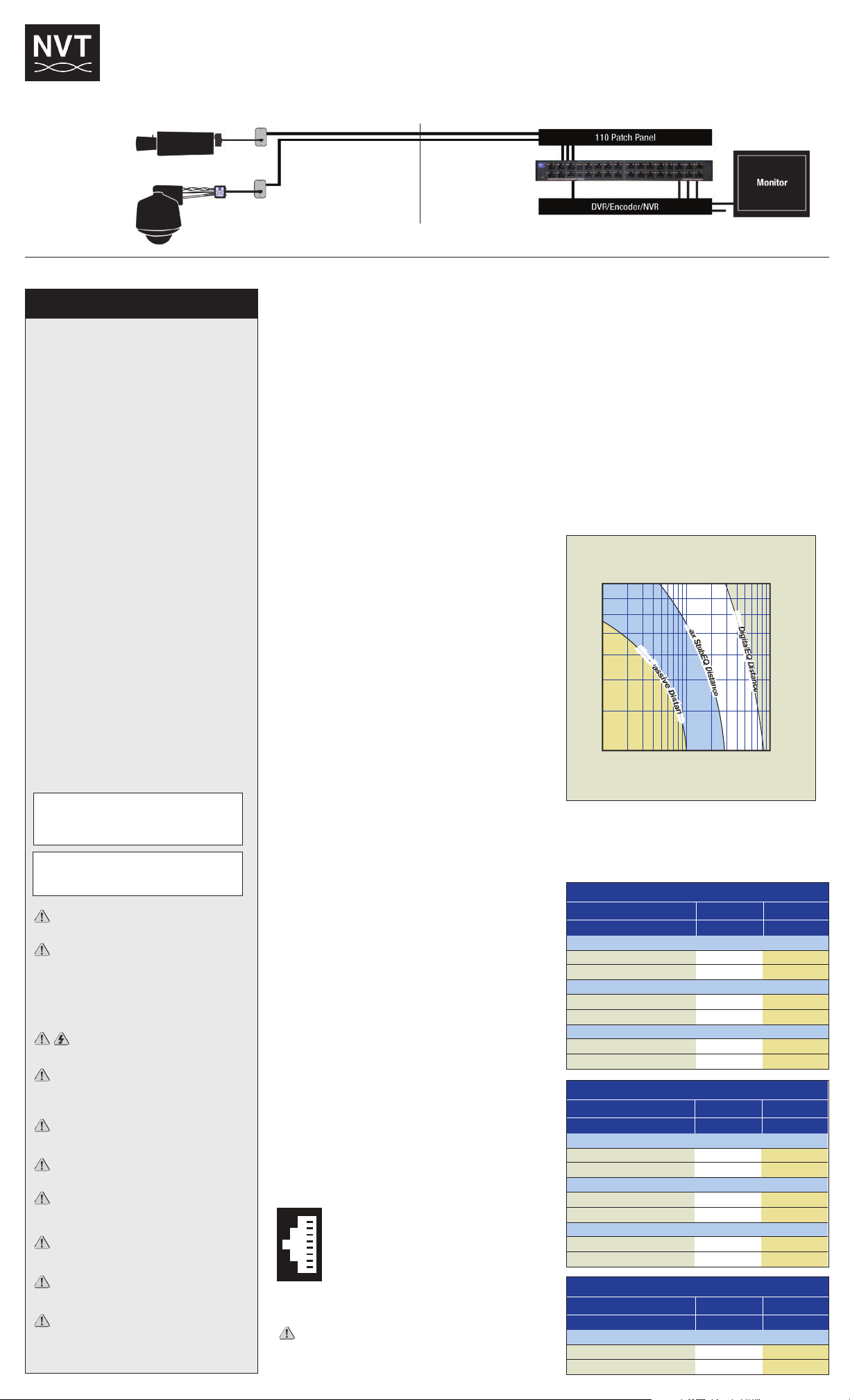
Fixed 12VDC Camera used with NV-226J-PV
Power Supply Voltage
1,586ft (748m)
1,999ft (609m)
795ft (242m)
1,002ft (306m)
2,220ft (677m)
2,799ft (853m)
1,113ft (339m)
1,403ft (428m)
B&W Camera, 2.4 W
2-pair 24 AWG
2-pair 23 AWG
Color Camera 4.8 W
2-pair 24 AWG
2-pair 23 AWG
24 VAC 28 VAC
This manual suits for next models
2
Table of contents
Other NVT Switch manuals
Popular Switch manuals by other brands

Eaton
Eaton N2-4-S1-DC Series Instruction leaflet

Harman
Harman AMX Precis PR Series Hardware reference manual

Extron electronics
Extron electronics SW2 DP user guide

Lumi
Lumi WXKG02LM quick start guide

socomec
socomec ATyS p instruction manual

Broadcast Tools
Broadcast Tools DMS-III Installation and operation manual