Sambo SBWG Series User manual

Operating instructions for SAMBO Worm Gear Operator V1.00-2021.04.29
Operating instructions for SAMBO SBWG series worm gear operator
1 Introduction
This installation and maintenance manual explains, how to install and maintain the Sambo SBWG operator.
Information on installation, disassembly, reassembly, lubrication and spare parts is provided.
Figure 1: Typical SBWG Exploded View
WARNING: Do not manually operate the SBWG operator (see figure 1) with devices other
than the installed handwheel or wrench nut. Using additive force devices (cheater bars,
wheel wrenches, pipe wrenches, or other devices of this nature) on the operator handwheel,
wrench or wrench nut may cause serious personal injury and/or damage to the operator or valve.
2 Safety instructions
NOTE: Read this installation, operation and maintenance manual carefully and completely before attempting
to install, operate or troubleshoot the SAMBO gearbox.
CAUTION: Work undertaken must be carried out in accordance with the instructions in this and
any other relevant manuals. The user and those persons working on this equipment should be
familiar with their responsibilities under any statutory provisions relating to the Health and Safety
of their workplace. Due consideration of additional hazards should be taken when using the gearbox with
other equipment. Should further information and guidance relating to the safe use of the SAMBO products be
required, it will be provided on request.
1

V1.00-2021.04.29 Operating instructions for SAMBO Worm Gear Operator
CAUTION: The mechanical installation should be carried out as outlined in this manual and also in
accordance with relevant standards. No inspection or repair should be undertaken unless it con-
forms to the specific hazardous area certification requirements. For maintenance of the actuator,
refer to the actuator installation and maintenance manual.
WARNING: Potential HIGH-PRESSURE vessel —be aware of high-pressure hazards associ-
ated with the attached valve or other actuated device when installing or performing mainte-
nance on the gearbox. Do not remove the gearbox mounting bolts from the valve or actuated
device unless the valve or device stem is secured or there is no pressure in the line.
CAUTION: For maintenance and/or disassembly of the gearbox while installed on the valve, ensure
that the gearbox is not under thrust or torque load. If the valve must be left in service, the valve stem
must be locked in such a way as to prevent any movement of the valve stem.
CAUTION: Do not exceed any design limitations or make modifications to this equipment without
first consulting SAMBO.
CAUTION: Use of this product must be suspended any time it fails to operate properly.
CAUTION: Damage to protective coatings should be correctly rectified and may invalidate war-
ranty.
CAUTION: If a motor actuator is driving the gearbox, do not operate the valve under motor operation
without first checking and setting the limit switch and checking for correct motor rotation.
WARNING: Do not use replacement parts that are not genuine SAMBO parts, as serious
personal injury and/or damage to the gearbox and valve may result.
2

Operating instructions for SAMBO Worm Gear Operator V1.00-2021.04.29
3 Storage
WARNING: Read this installation and maintenance manual carefully and completely before
attempting to store the operator. If an electric actuator is attached to the SBWG manual
operator, be aware of the electrical hazards. Consult the electric actuator installation and
maintenance manual for guidance.
NOTE: The following is the recommended storage procedure to retain maximum product integrity during stor-
age. Failure to comply with recommended procedure will void the warranty.
Storage (less than one year)
Store the gearboxes on wooden skids to protect the machined mounting flange. Place the wooden skids
containing the gearboxes in a clean, dry, protected warehouse. If the gearboxes must be stored outside, they
must be covered in polyethylene protection with silica gel crystals to absorb moisture.
If an electric actuator is attached to the V gearbox, refer to the storage procedures in its respective manual for
appropriate storage procedures. Rotate input shafts every three months tomix the lubricant.
Recommended storage temperature range: 0°C to 40°C (32°F – 104°F).
4 Unpacking
Gearboxes are packed in a variety of configurations depending on size, type and quantity of the consignment.
It is the responsibility of the individual unpacking and handling the combination to carry out a risk assessment
for the supplied arrangement to ensure safe working.
Packaging material used may include wood, cardboard, polyethylene and steel. Packaging should be recycled
according to local regulations.
5 Handling
Individual weights for gearboxes are recorded on their respective nameplates.
CAUTION: Only trained and experienced personnel should carry out handling. At all times, safe
handling must be ensured.
Each combination must be assessed to identify all risks associated with handling.
The gearboxes must be fully supported until full valve shaft/stem engagement is achieved and the gearbox
is secured to the valve flange.
Once connected to the valve, each assembly must be assessed on an individual basis for safe handling/lifting.
Never lift the complete combination-valve assembly via the gearbox.
If it is necessary to lift the gearbox using lifting equipment, certified soft slings are recommended. Damage to
protective coatings should be correctly rectified and may invalidate warranty.
6 General Mounting Instructions
CAUTION: To avoid the potential for disengaging the worm gear segment, ensure that the pointer
cap pointer is oriented to the mid-point of the 90º valve travel. Full stroke rotation of the quadrant
should not move the pointer past the corresponding Open or Close ID marks on the housing cover.
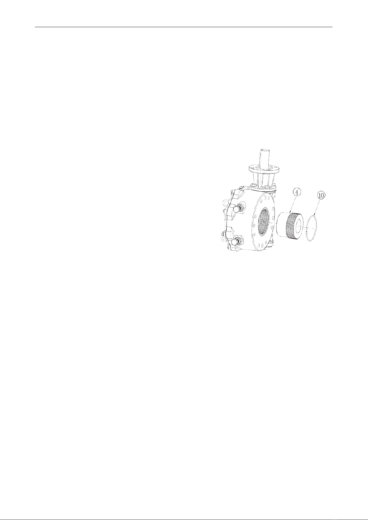
The mounting instructions for the SBWG series worm gearboxes are outlined below. The SBWG-00 through
SBWG-35 gearboxes are designed with a bottom entry splined adapter. The SBWG-04 through SBWG-12
3

V1.00-2021.04.29 Operating instructions for SAMBO Worm Gear Operator
gearboxes are designed with a top entry splined adapter. A separate set of instructions for each design is
provided. See Section 6.1 for the SBWG-00 through SBWG-35 and Section 6.2 for the SBWG-04 through
SBWG-12.
6.1 SBWG-00 through SBWG-35
1. Place the valve disk in the full closed position.
NOTE: If the Splined Adapter is already installed in the operator, go to step 6.
2. Remove the Pointer Cap.
3. Turn the gearbox upside down so that the bottom of the housing is accessible.
4. Remove the Retaining Ring, and install the Splined Adapter.
NOTE: The notch in the Worm Gear at the Closed position must be aligned with the keyway in the Splined
Adapter.
5. Reinstall the Retaining Ring.
6. Place the gearbox in the upright position so that the top of the gearbox is accessible.
7. Mount the operator on the valve and bolt securely.
8. Rotate the input shaft to align the keyway of the Splined Adapter with the keyway of the Valve Shaft and
install the key.
9. Confirm that the gearbox Stop Screws are properly set for valve disk travel in both the Open and Close
directions of travel. See Section 6.4.
10. Reinstall the Pointer Cap.
6.2 SBWG-04 through SBWG-12
1. Place the valve disk in the full closed position.
2. Remove the Pointer Cap (see section 8.4 for removal instructions).
NOTE: If the Splined Adapter is already installed in the operator, go to step 6.
3. Remove the Retaining Ring and install the Splined Adapter.
NOTE: The notch in the Worm Gear at the Closed position must be aligned with the keyway in the Splined
Adapter.
4. Reinstall the Retaining Ring.
5. Mount the operator on the valve and bolt securely.
6. Rotate the input shaft to align the keyway of the Splined Adapter with the keyway of the Valve Shaft and
install the key.
7. Confirm that the gearbox Stop Screws are properly set for valve disk travel in both the Open and Close
directions of travel. See Section 6.4.
8. Reinstall the Pointer Cap.
4

Operating instructions for SAMBO Worm Gear Operator V1.00-2021.04.29
6.3 Assembly Positions
Figure 2: Position A (above), Position B (below)
6.4 Setting Position Limit Stops – SBWG-00 Through SBWG-12
Refer to figure 3
1. Loosen the Hex Nut (item no. 16) and turn it several turns to allow for stop screw adjustment.
2. Adjust the Stop Screw by turning it counterclockwise to back the screw away from the Worm Gear/Drive
Sleeve (item no. 5).
3. Place the valve disk in the full closed position.
4. Turn the Stop Screw (item no. 15) in the clockwise direction until the end of the screw contacts the Worm
Gear/Drive Sleeve.
5. Tighten the Hex Nut to secure the closed set position.
6. Move the valve disk to the full open position.
7. Follow steps 1 through 5.
CAUTION: If the valve is operated with an electric actuator/gear operator combination, and the
valve is position-seated, set the actuator limit switches to trip prior to engagement of the SBWG
Worm Gear/Drive Sleeve with the Stop Screws. Damage to the operator could result from the Worm
Gear/Drive Sleeve contacting the Stop Screw under motorized operation.
NOTE: The stops are adjustable to +/- 5º of total travel to allow for proper positioning of the worm gear quadrant.
5
Table of contents
Other Sambo Industrial Equipment manuals