SAMES KREMLIN Airmix 120-10/120 User manual

DOCUMENTATION
AIRMIX® BACK PRESSURE
FLUID REGULATOR
120 - 10 / 120
Manual : 582.160.110-UK - 2002
Date: 20/02/20
Supersede :
Modif.:
TRANSLATION FROM THE ORIGINAL MANUAL
IMPORTANT :Before assembly and start-up, please read and clearly understand all the documents relating to
this equipment (professional use only).
THE PICTURES AND DRAWINGS ARE NON CONTRACTUAL. WE RESERVE THE RIGHT TO MAKE CHANGES WITHOUT PRIOR NOTICE.
SAMES KREMLIN SAS
l
13, chemin de Malacher
38 240 - MEYLAN - France
: 33 (0)4 76 41 60 60
www.sames-kremlin.com

INSTRUCTION MANUAL
PRESSURE REGULATOR
for fluid or semi-fluid materials
Manual : 2002 573.008.212
Date : 11/02/20 - Supersede : 03/03/14
Modif. : Update
TRANSLATION FROM THE ORIGINAL MANUAL
IMPORTANT : Before assembly and start-up, please read and clearly understand all the
documents relating to this equipment (professional use only).
THE PICTURES AND DRAWINGS ARE NON CONTRACTUAL. WE RESERVE THE RIGHT TO MAKE CHANGES WITHOUT PRIOR
NOTICE.
SAMES KREMLIN SAS
l
13, chemin de Malacher
38 240 - MEYLAN - France
: 33 (0)4 76 41 60 60
www.sames-kremlin.com

SAMES KREMLIN Page 1 Manual : 573.008.212
INSTRUCTION MANUAL
PRESSURE REGULATOR
for fluid or semi-fluid materials
TABLE OF CONTENTS
1.GENERAL SAFETY INSTRUCTIONS ........................................................................................................ 2
2.DESCRIPTION............................................................................................................................................. 3
3.MOUNTING.................................................................................................................................................. 4
4.INSTALLATION ........................................................................................................................................... 4
5.START UP.................................................................................................................................................... 5
6.MAINTENANCE........................................................................................................................................... 5
7.TROUBLESHOOTING CHART ................................................................................................................... 6
The specifications of the regulator - features and maintenance - are available in a
documentation enclosed to the manual.

SAMES KREMLIN Page 2 Manual : 573.008.212
Dear Customer,
You are the owner of our new SAMES KREMLIN pressure regulator and we would like to take this
opportunity to thank you.
To make sure your investment will provide full satisfaction, special care has been taken by SAMES
KREMLIN during all designing and manufacturing processes.
To obtain the best result, safe and efficient operation of your equipment, we advice you to read and
make yourself familiar with this instruction and service manual. Indeed, the non-compliance with
instructions and precautions stated in this manual could reduce the equipment working life, result in
operating trouble and create unsafe conditions.
1. GENERAL SAFETY INSTRUCTIONS
WARNING : Any misuse of the equipment or accessories can damage them, result in serious
body injury, fire or explosion hazard and reduce the equipment working life. Read,
understand and comply with the safety instructions hereafter.
The personnel involved in operating and servicing this equipment must be aware of all safety
requirements stated in this manual. The workshop supervisor must be certain that the personnel has
perfectly understood the safety instructions and complies with them.
Read all instruction manuals as well as the tags of the equipments before operating the equipment.
Refer to local safety instructions and comply with them.
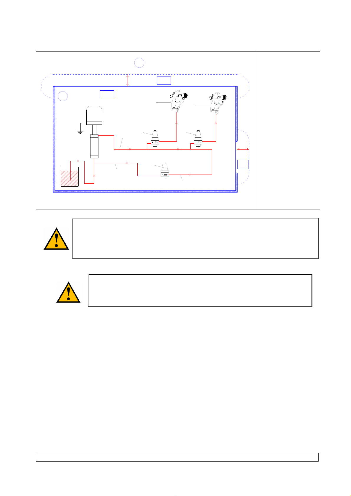
INSTALLATION REQUIREMENTS
Ground the equipments.
Use the equipment only in a well-ventilated area to prevent from serious body injuries, fire and
explosion hazards. Do not smoke in the spray area.
Never stock paints and solvents in the spray area. Always close the pots and the tins.
Always keep the spray area clean and free from debris (solvent, rags,…).
Read paint and solvent manufacturer's technical instructions.
Spraying of some materials may result in hazardous working conditions. To protect the operator,
respirator mask, hand cream, glasses and hearing protective earplug are required (Refer to chapter "
Safety equipment" of SAMES KREMLIN selection guide).
EQUIPMENT REQUIREMENTS
The operating pressure of these equipments are particularly high. Consequently, some precautions
must be taken in order to prevent from accidents and from unsafe working conditions.
Never exceed the components maximum pressure of the equipment.
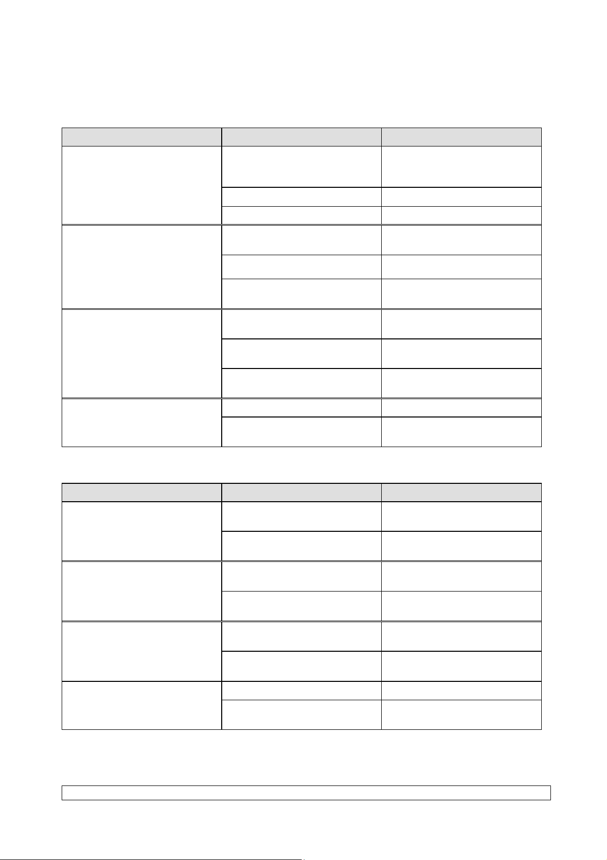
HOSES
Do not use hoses with a maximum burst-proof pressure less than four times the maximum service
pressure of the pump (see data sheet).
Be certain the hoses are not crimped, leaking and not unrolled.
Be certain hoses are in good conditions and showing no evidence of damage.
Use only air hose with static conductor to connect the pump with the spray gun.
All fittings must be tight and in good condition.
PUMP
Ground the equipment (use the connection on the pump).
Do not use any product or solvent incompatible with the pump components.
Use the appropriate solvent for the material being sprayed to increase the equipment working life.

SAMES KREMLIN Page 3 Manual : 573.008.212
GUN
Never wipe the end of the tip with the fingers.
Always depressurize air and hoses before carrying out any servicing on the gun.
Never point the spray gun at anyone or at any part of the body.
PRESSURE REGULATOR
Assemble conductive hoses upstream and downstream of the regulator.
MAINTENANCE REQUIREMENTS
Guards (air motor cover, coupling shields, housings …) have been designed for
safe use of the equipment.
The manufacturer will not be held responsible for bodily injury or failure and / or
damage to property due to removal or partial removal of the guards.
Never modify these equipments.
Check them daily, keep them in a good condition and replace the worn parts only with SAMES
KREMLIN parts.
Before cleaning or removing components of the equipment, it is compulsory :
- to stop the pump by shutting off the compressed air supply,
- to open the pump drain valve,
- to press the gun trigger to depressurize the hoses.
2. DESCRIPTION
The pressure regulator enables to adjust the fluid pressure into the circuits of low and medium pressure.
The pressure regulator is mounted on the fluid circuit between the pump fluid outlet and the gun fluid inlet.
It enables to refine the pressure of the gun. It exits a spring operated model and an air operated model.
The back pressure regulator is mounted on the back fluid circuit. It enables to regulate a constant
pressure and to ensure at the same time a fluid circulation into the hoses.

SAMES KREMLIN Page 4 Manual : 573.008.212
3. MOUNTING
Support (optional)
P
J
PQ
O
N
HM
K
L
R
I
Ind. mm " Ind. mm " Ind. mm " Ind. mm "
H 16 0.63 I 10 0.4 J Ø 6.5 Ø 0.25 K 25 0.98
L 20 0.79 M 8 0.31 N 3 0.12 O 90 3.54
P 22.5 0.88 Q 65 2.56 R 25 0.98
4. INSTALLATION
The pressure regulators are designed to be installed in a spraybooth.
INSTALLATION DIAGRAM WITHOUT CIRCULATING
1
2
B
AZ1
Z2
Z2
1m
1m
3
55
4
A -
B -
1 -
2 -
3 -
4 -
5 -
Explosive area
area 1 (Z1)
or area 2 (Z2) :
spraybooth
Non explosive
area
Pump
Gun
Spring operated
pressure regulator
or
Air operated
pressure regulator
Conductive hose

SAMES KREMLIN Page 5 Manual : 573.008.212
INSTALLATION DIAGRAM WITH CIRCULATING
1
B
AZ1
Z2
Z2
1m
1m
6
5
5
5
3 3
22
A -
B -
1 -
2 -
3 -
5 -
6 -
Explosive area
area 1 (Z1)
or area 2 (Z2) :
spraybooth
Non explosive
area
Pump
Gun
Pressure regulator
(spring or air
operated)
Conductive hose
Back pressure
regulator
The 1 m / 39.37" distance indicated in these diagrams is given for information
purposes only and hold harmless to SAMES KREMLIN. The user is responsible for the
extraction and conditioning of the painting area where the equipment is used, for
working conditions conditions (refer to EN 60079-10 standard). The 1 m / 39.37"
distance may be modified if trials carried out by the user deem this necessary.
(Nota : diagrams represented with Airmix® regulators)
NOTA :
To ensure a larger lifetime of your equipment and to obtain the best flow
rate possible, you must mount the regulator in vertical position.
5. START UP
Start up the pump (Refer to pump instruction manual).
Tighten the screw located on the upper part of the spring operated regulator or turn the regulator of the air
operated assembly.
Start up the gun (Refer to gun instruction manual).
Adjust the fluid regulator to obtain the required pressure and fluid flow.
Nota : Refer to the regulator features to comply with the inlet and outlet pressures (refer to the
enclosed document).
6. MAINTENANCE
Keep the pressure regulator clean to ensure its proper working.
When flushing the pump, make the solvent circulate in circuit to clean all the elements (pump, hoses,
regulator, gun).

SAMES KREMLIN Page 6 Manual : 573.008.212
7. TROUBLESHOOTING CHART
PRESSURE REGULATOR (AIR OR SPRING OPERATED)
TROUBLE CAUSE SOLUTION
Overpressure at the regulator
outlet
Adjustment screw or adjustment
knob of the regulator turned
clockwise (full closed)
Unscrew adjustment screw or
knob.
Air pilot pressure too high Decrease pilot pressure.
Bad tightness of seat and ball Clean or replace.
No material coming out from the
regulator
Adjustment screw or knob turned
counter-clockwise (full open) Screw adjustment screw or knob.
Air pilot pressure insufficient Increase pilot air pressure.
Ball blocked on the seat, needle
broken Clean and reinstall or change.
Irregular flow rate
Too much pulsation in the fluid
network Adjust inlet pressure.
Improper proofness of seat, ball
and spring Clean or replace.
Regulator in horizontal position Mount the regulator in vertical
position
Leakage at the upper part of the
regulator
Defective fluid diaphragm Replace it.
Screws improperly tightened on
the lower body Tighten up the screws.
BACK PRESSURE REGULATOR
DEFECT CAUSE SOLUTION
Overpressure upstream of the
regulator
Adjustment screw or knob turned
clockwise (full closed)
Turn the adjustment screw or
knob counter-clockwise.
Pressure too high in the fluid
circuit (or circulating) Decrease pressure.
Pressure drop upstream of the
regulator
Adjustment screw or knob turned
counter-clockwise (full open)
Screw the adjustment screw or
knob.
Improper fluid proofness of seat
and ball Clean and reinstall.
Irregular circulation
Too important pulsation in the
fluid network Check and adjust inlet pressure.
Improper proofness of seat and
ball Clean or replace.
Material leakage at the upper
body of the regulator
Defective fluid diaphragm Replace it.
Loosened screws on the upper
body Tighten up the screws.

SPECIFICATIONS
STAINLESS STEEL AIRMIX®
BACK PRESSURE FLUID
REGULATOR
Model : 120 - 10 / 120
Manual : 2002 573.042.212
Date : 11/02/20 - Supersede : 03/03/14
Modif. : Update
TRANSLATION FROM THE ORIGINAL MANUAL
IMPORTANT : Before assembly and start-up, please read and clearly understand all the
documents relating to this equipment (professional use only).
PICTURES AND DRAWINGS ARE NON CONTRACTUAL. WE RESERVE THE RIGHT TO MAKE CHANGES WITHOUT
PRIOR NOTICE.
ADDITIONAL DOCUMENTATIONS
SPARE PARTS : AIRMIXback pressure fluid regulator (Doc. 573.343.050)
SAMES KREMLIN SAS
l
13, chemin de Malacher
38 240 - MEYLAN - France
: 33 (0)4 76 41 60 60
www.sames-kremlin.com

SAMES KREMLIN Page 1 Manual : 573.042.212
SPECIFICATIONS
STAINLESS STEEL AIRMIX® BACK PRESSURE FLUID
REGULATOR
Manual control
Model : 120 - 10 / 120
1. TECHNICAL FEATURES
The AIRMIXback pressure fluid regulator is used on installations that drive fluid or semi thick materials.
It is in stainless steel and designed for easy flushing.
The fluid pressure adjustment is carried out at the regulator outlet by screwing or unscrewing the
adjustment screw (with the wrench n° 6).
An arrow marked on the body indicates the fluid inlet and the fluid outlet.
Ind. mm " Ind. mm " Ind. mm "
A 225 8.85 B 89 Ø 3.5 C 16 0.6

SAMES KREMLIN Page 2 Manual : 573.042.212
Type Manual control regulator (by screws)
Version 120 - 10 / 120
Pressure range :
- Inlet pressure Maximum 120 bar / 1740 psi
- Outlet pressure From 10 to 120 bar / from 145 to 1740 psi
Fittings :
- Fluid inlet (E) F 3/8 NPS
- Fluid outlet (S) F 3/8 NPS
Wetted parts Stainless steel, PTFE, carbide
Weight 3.6 kg / 7.9 lb
Maximum temperature 50°C / 122°F
HOSES WITH FITTINGS RECOMMENDED
You must choose the hose according to the material viscosity and to the length. Make sure the hose
has a larger diameter for higher length or important viscosity.
Airmix ®
regulator
Fluid material Semi thick material
Fitting AIRMIXhose Fitting AIRMIXhose
Inlet (E) M 3/8 NPT - M 1/2 JIC 4,8mm int. (1/4") M 3/8 NPT - M 3/4 JIC 4,8 mm int. (3/16")
or 6,35 mm int. (1/4")
Outlet (S) M 3/8 NPT - M 1/2 JIC 4,8 mm int. (3/16")
or 6,35 mm int. (1/4")
M 3/8 NPT - M 1/2 JIC 4,8 mm int. (3/16")
or 6,35 mm int. (1/4")
NOTA :
To ensure a larger lifetime of your equipment and to obtain the best flow
rate possible, you must mount the regulator in vertical position.
2. MAINTENANCE
WARNING : Before any action on the installation, shut off the compressed air
supply and depressurize the systems by triggering the spray gun.
REPLACEMENT OF THE SEAT (23)
Removal :
Unscrew the 4 screws (18) and remove the lower body (10).
Unscrew the plug (27). Remove the guide bush (21).
Push on the seat (23) to remove it from the lower body (10).
Clean the parts or replace with new parts.
Reassembly :
Change the 2 seals (26), the seat (23).
Remount the seat (23), the guide bush (21) and the plug (27).
Remount the lower body (10) and fix it via the 4 screws (18) Respect the screwing torque.

SAMES KREMLIN Page 3 Manual : 573.042.212
REPLACEMENT OF THE PIN-BALL ASSEMBLY (11) OR OF THE DIAPHRAGMS (13 & 14)
Removal :
Unscrew the 4 screws (18) and remove the lower body (10).
Unstick the diaphragms from the upper body (19).
Pull carefully the diaphragms to remove the pin-ball assembly (11), the piston (16) and the nut (17).
Do not pull the ball. This would damage the parts.
Unscrew the nut (17) to remove the piston (16).
Remove the black diaphragm (13) and the white washer support (14).
Clean the parts or replace with new parts.
Reassembly :
Replace the seal (15), placed on the pin-ball assembly (11) and the seal (20).
Place the black diaphragm (13) to the air side, the white washer support (14) to the fluid side, and the
piston (16).
Place the pin (11) into a vice and tighten at the 2 flats.
Glue with a coating of glue the axis threading (11).
Screw the nut (17) on the pin-ball assembly without using tools, then screw it slightly with a
wrench n° 8.
Install the assembly into the upper body (19).
Remount the lower body (10) with the seat (23) and fix it via the 4 screws (18). Respect the screwing
torque.
IMPORTANT : when reassembling, the ball of the pin-ball assembly (11) must be on the
central port of the seat (23).
Before reassembling the different components :
- Clean the parts with the appropriate cleaning solvent.
- Install new parts if necessary after having lubricated them with PTFE grease.
- Install new parts if necessary.

SAMES KREMLIN Page 4 Manual : 573.042.212
ASSEMBLY INSTRUCTIONS
2
1
6
3
4
5
A 2
A 1
A 1
A 1
A 2
21
15
14
13
11
16
17
19
27
26
18
23
10
20
12 A 2
A 1
A 1
C 1
S 1
Index Instruction Description Part number
A 1 PTFE grease 'TECHNILUB' grease
(10 ml / 0.0026 US gal) 560.440.101
A 2 Anti-seize grease Grease box (450 g / 0.99 lb) 560.420.005
C 1 Medium strength
Aneorobic Pipe sealant
Loctite 577 (250 ml / 0.066 US gal) 554.180.015
S 1 Screwing torque : 20 Nm / 14.75 ft/lbs

Doc. 573.343.050
Date/Datum/Fecha : 11/02/20
Annule/Cancels/
Ersetzt/Anula : 11/10/13
Modif. / Änderung :
Mise à jour / Update / Aktualisierung
/ Actualización
Pièces de rechange
Spare parts list
Ersatzteilliste
Piezas de repuesto
REGULATEUR DE PRESSION DE RETOUR
AIRMIX
AIRMIXBACK PRESSURE FLUID
REGULATOR
AIRMIX-MATERIAL-RÜCKDRUCKREGLER REGULADOR DE PRESION DE RETORNO
AIRMIX
REGULATEUR A COMMANDE
MANUELLE
MANUAL CONTROL REGULATOR
DRUCKREGLER MIT
HANDSTEUERUNG
REGULADOR CON MANDO
MANUAL
Modèle / Model / Modell / tipo :
120 - 10 / 120
# 155.271.835
A
B
30

SAMES KREMLIN 2 Doc. / Dok. : 573.343.050
A B
2
1
6
3
4
5
21
15
14
13
11
16
17
19
27
26
18
23
10
20
12
A COMMANDE MANUELLE / MANUAL CONTROL / HANDSTEUERUNG / MANDO MANUAL
Ind # Désignation Description Bezeichnung Denominación Qté
1 055 271 721 Chapeau Hat Regler, Oberteil Tapa 1
2 055 271 727 Vis de réglage Adjustment screw Schraube Tornillo de ajuste 1
3 055 271 724 Guide Guide Führung Guía 1
4 050 319 406 Ressort (rouge) Spring (red) Feder (rot) Muelle (rojo) 1
5 055 271 726 Coupelle Spring support Federführung Copa 1
6 930 151 196 Vis CHc M 6 x 16 Screw, CHc M 6 x 16 Schraube, CHc M 6 x 16 Tornillo CHc M 6 x 16 4

SAMES KREMLIN 3 Doc. / Dok. : 573.343.050
B PARTIE PRODUIT / PRODUCT PART / MATERIALTEIL / PARTE PRODUCTO
Ind # Désignation Description Bezeichnung Denominación Qté
10 055 271 801 Corps inférieur Body, lower Körper, Unterteil Cuerpo inferior 1
11 155 271 805 Ensemble axe-bille Pin-ball assembly Achse-Kugel kpl. Conjunto eje-bola 1
*12 155 271 902 Membrane équipée Diaphragm assembly Membraneinheit Membrana equipada 1
13 NC / NS Membrane Diaphragm Luftmembran Membrana 1
14 NC / NS Contre membrane Washer support Materialmembran Contra membrana 1
15 150 040 332 Joint torique, PTFE
(pochette de 10)
O-Ring, PTFE
(pack of 10)
PTFE-Dichtung (10 St.) Junta O-Ring, PTFE
(bolsa de 10)
1
*16 055 271 709 Piston Piston Materialkolben Pistón 1
17 953 010 014 Ecrou HM5 Nut, HM5 Mutter, HM5 Tuerca, HM5 1
18 88 173 Vis CHc M 10 x 50 Screw, CHc M 10 x 50 Schraube, CHc M 10 x 50 Tornillo CHc M 10 x 50 4
19 055 271 710 Entretoise de guidage Body, upper Körper, Oberteil Cuerpo guía 1
20 150 040 309 Joint torique, PTFE
(pochette de 10)
O-Ring, PTFE
(pack of 10)
PTFE-Dichtung (10 St.) Junta O-Ring, PTFE
(bolsa de 10)
1
21 055 271 802 Bague de guidage Guide bush Führungsbuchse Anillo de dirección 1
23 055 271 210 Siège Seat Sitz Asiento 1
26 150 040 314 Joint torique, PTFE
(pochette de 10)
O-Ring, PTFE
(pack of 10)
PTFE-Dichtung
(Satz mit 10 St.)
Junta O-Ring, PTFE
(bolsa de 10)
2
27 055 271 703 Bouchon Plug Stopfen Tapón 1
* 155 271 905 Pochette de
maintenance (ind. 11,
12, 20, 23, 26 (x2))
Servicing kit
(ind. 11, 12, 20, 23,
26 (x2))
Servicekit
(Pos. 11, 12, 20, 23,
26 (2x))
Bolsa de reparación
(índ. 11, 12, 20, 23,
26 (x2))
1
* Pièces de maintenance préconisées.
* Preceding the index number denotes a suggested spare part.
* Bezeichnete Teile sind empfohlene Ersatzteile.
* Piezas de mantenimiento preventivas.
N C : Non commercialisé.
N S : Denotes parts are not serviceable separately.
N S : bezeichnete Teile gibt es nicht einzeln, sondern nur
komplett.
N C : no suministrado.
ACCESSOIRES - ACCESSORIES - ZUBEHÖR - ACCESORIOS
Ind # Désignation Description Bezeichnung Denominación Qté
30 906 300 213 Clé de 6 Wrench Inbusschlüssel, Größe 6 Llave 1

SAMES KREMLIN 4 Doc. / Dok. : 573.343.050
OPTION - ON REQUEST - OPTIONAL - OPCIÓN
# Désignation Description Bezeichnung Denominación
155 484 010 Support pour
régulateur
Support, regulator Wandhalterung für
Regler
Soporte para regulador
155 271 790 Manomètre à
membrane équipé
(0-250 bar)
Diaphragm pressure
gauge
(0-250 bar / 0-3625 psi)
Manometer mit
Membran-Druckmittler
(0-250 bar)
Manómetro con
membrana equipado
(0-250 bar)
910 010 802 Manomètre
(63, 0-120 bar,
M 1/4" BSP)
Gauge (63,
0-120 bar / 0-1740 psi,
M 1/4"BSP)
Manometer
(63, 0-120 bar,
AG 1/4"BSP)
Manómetro
(63, 0-120 bar,
M 1/4"BSP)
Régulateur de retour AIRMIX®
équipé pour montage à
l'aspiration des pompes
AIRMIX® back pressure
regulator - Pre-equipped for
pump inlet mounting
AIRMIX® Rückdruckregler
ausgerüstet für die Montage in
den Ansaug der Pumpe
Regulador de retorno AIRMIX®
equipado para su montaje a la
aspiración de las bombas
# 051.314.030
Ind # Désignation Description Bezeichnung Denominación Qté
31 155 271 835 Régulateur de retour
Airmix®
Airmix® back pressure
regulator
Airmix®-Rückdruckregler Regulador de presion
Airmix®
1
32 155 484 010 Support pour régulateur Support, regulator Wandhalterung Soporte para regulador 1
33 000 750 040 Robinet HP 3/8 NPT HP valve, 3/8" NPT HD-Hahn 3/8" NPT Grifo AP 3/8" NPT 1
34 049 596 000 Canne de purge Flushing rod Umlaufschlauch, kpl Caña de purga 1
35 050 450 704 Tuyau Airmix®, 1/4",
longueur 2 m
Airmix® hose, 1/4",
length : 2 m / 6.6 ft
Airmix®-Schlauch,
1/4", Länge 2m
Tubería Airmix®, 1/4",
longitud 2m
1
36 051 314 013 Raccord d'aspiration
(MM 1/2" - 26x125)
Pump inlet fitting
(1/2" male - 26x125 male)
Anschlußnippel
(AG 1/2" - AG M 26x1,25)
Racord de aspiración
montado
(MM 1/2" - 26x125)
1
1/2 JIC
31+32
33
34
35
36
M 26x125
M 1/2
Table of contents
Other SAMES KREMLIN Controllers manuals
Popular Controllers manuals by other brands

Watlow
Watlow Integrated Controller Rev C EZ-ZONE PM user manual

SKYDANCE
SKYDANCE RGBW user guide

Honeywell
Honeywell H46C installation instructions

Bticino
Bticino AXOLUTE HD4657M3 quick start guide

Doepke
Doepke Dupline DNP 4 operating instructions

Siko
Siko AG03/1 Translation of the original installation instructions