SAMES KREMLIN PPH 308 User manual

Index revision : F - November 2017 1 7012
User manual
SAMES KREMLIN SAS - 13, Chemin de Malacher - 38240 MEYLAN - FRANCE
Tel. 33 (0)4 76 41 60 60 - www.sames-kremlin.com
PPH 308 atomizer,
single circuit without regulator with
coil
for solvented paints

Index revision : F - November 2017 2 7012
All communication or reproduction of this document, in any form whatsoever and all use or
communication of its contents are forbidden without express written authorisation from
SAMES KREMLIN.
The descriptions and characteristics mentioned in this documentare subject to change without
prior notice.
© SAMES KREMLIN 2006
WARNING : SAMES KREMLIN SAS is registered with the Ministry of Labour as a training
institution.
Throughout the year, our company offers training courses in the operation and
maintenance of your equipment.
A catalogue is available on request. Choose from a wide range of courses to
acquire the skills or knowledge that is required to match your production
requirements and objectives.
Our training courses can be delivered at your site or in the training centre at our
Meylan head office.
Training department:
Tel. 33 (0)4 76 41 60 04
E-mail: formation-clie[email protected]
SAMES KREMLIN SAS operating manuals are written in French and translated into English, German, Spanish, Italian
and Portuguese.
The French version is deemed the official text and SAMES KREMLIN will not be liable for the translations into other
languages.

Index revision : 3
PPH 308 atomizer,
single circuit without regulator with coil
for solvented paints
1. Health and Safety Instructions - - - - - - - - - - - - - - - - - - - - - - - - - - - - 5
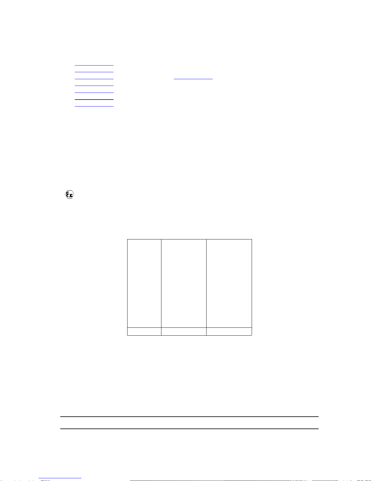
1.1. Configuration of the certified equipment . . . . . . . . . . . . . . . . . . 5
1.2. Marking on the atomizer . . . . . . . . . . . . . . . . . . . . . . . . . . . . . . 5
1.3. Precautions for Use . . . . . . . . . . . . . . . . . . . . . . . . . . . . . . . . . . 6
1.4. Warnings . . . . . . . . . . . . . . . . . . . . . . . . . . . . . . . . . . . . . . . . . . 6
1.4.1. Installation rules. . . . . . . . . . . . . . . . . . . . . . . . . . . . . . . . . . . . . . 9
1.5. Important Recommendations . . . . . . . . . . . . . . . . . . . . . . . . . 10
1.5.1. Paint Resistivity . . . . . . . . . . . . . . . . . . . . . . . . . . . . . . . . . . . . . 10
1.5.2. Compressed Air Quality. . . . . . . . . . . . . . . . . . . . . . . . . . . . . . . 10
1.5.3. Product Quality . . . . . . . . . . . . . . . . . . . . . . . . . . . . . . . . . . . . . 11
1.5.4. Bearing Safety . . . . . . . . . . . . . . . . . . . . . . . . . . . . . . . . . . . . . . 11
1.5.5. Locking. . . . . . . . . . . . . . . . . . . . . . . . . . . . . . . . . . . . . . . . . . . . 11
1.5.6. Shaping Air . . . . . . . . . . . . . . . . . . . . . . . . . . . . . . . . . . . . . . . . 11
1.5.7. High Voltage . . . . . . . . . . . . . . . . . . . . . . . . . . . . . . . . . . . . . . . 11
1.5.8. Maximum Speed . . . . . . . . . . . . . . . . . . . . . . . . . . . . . . . . . . . . 12
1.5.9. Vibrations. . . . . . . . . . . . . . . . . . . . . . . . . . . . . . . . . . . . . . . . . . 12
1.5.10. Bell Cup / Turbine Fitting . . . . . . . . . . . . . . . . . . . . . . . . . . . . . 12
1.5.11. O-ring Seals. . . . . . . . . . . . . . . . . . . . . . . . . . . . . . . . . . . . . . . 12
1.5.12. Ventilation . . . . . . . . . . . . . . . . . . . . . . . . . . . . . . . . . . . . . . . . 12
1.5.13. Residual pressure . . . . . . . . . . . . . . . . . . . . . . . . . . . . . . . . . . 12
1.5.14. Safety devices . . . . . . . . . . . . . . . . . . . . . . . . . . . . . . . . . . . . . 13
1.5.15. Mechanical Collision . . . . . . . . . . . . . . . . . . . . . . . . . . . . . . . . 13
1.5.16. Ambient Temperature . . . . . . . . . . . . . . . . . . . . . . . . . . . . . . . 13
1.5.17. Sound level . . . . . . . . . . . . . . . . . . . . . . . . . . . . . . . . . . . . . . . 13
1.5.18. Specific maintenance provisions . . . . . . . . . . . . . . . . . . . . . . . 13
1.6. Guarantee . . . . . . . . . . . . . . . . . . . . . . . . . . . . . . . . . . . . . . . . 14
2. Description - - - - - - - - - - - - - - - - - - - - - - - - - - - - - - - - - - - - - - - - - 15
2.1. 2-Way Air / Solvent MicroValve Block (1-Pneumovalve Block) 16
2.2. High Voltage Unit UHT 155 EEx em . . . . . . . . . . . . . . . . . . . . 16
2.3. MANIFOLD block . . . . . . . . . . . . . . . . . . . . . . . . . . . . . . . . . . . 16
2.4. Injector, injector holder, restrictor . . . . . . . . . . . . . . . . . . . . . . 16
2.5. Magnetic air bearing turbine type ”BTM” . . . . . . . . . . . . . . . . . 17
2.5.1. Turbine Rotation Speed. . . . . . . . . . . . . . . . . . . . . . . . . . . . . . . 18
2.6. Shaping air . . . . . . . . . . . . . . . . . . . . . . . . . . . . . . . . . . . . . . . 18
2.7. Outer Cover . . . . . . . . . . . . . . . . . . . . . . . . . . . . . . . . . . . . . . . 19
2.7.1. Rinsing the external bellcup. . . . . . . . . . . . . . . . . . . . . . . . . . . . 19
2.8. Bell cups . . . . . . . . . . . . . . . . . . . . . . . . . . . . . . . . . . . . . . . . . 19
3. Characteristics of the PPH 308 Atomizer- - - - - - - - - - - - - - - - - - - - 20
3.1. Dimensions (mm) . . . . . . . . . . . . . . . . . . . . . . . . . . . . . . . . . . 20
3.2. Operating characteristics . . . . . . . . . . . . . . . . . . . . . . . . . . . . . 21
4. Diagram of the various fluid circuits- - - - - - - - - - - - - - - - - - - - - - - - 22
4.1. Paint diagram . . . . . . . . . . . . . . . . . . . . . . . . . . . . . . . . . . . . . 22

Index revision : 4
4.2. Bellcup and injector rinsing diagrams . . . . . . . . . . . . . . . . . . . 22
4.3. Microphone air diagram . . . . . . . . . . . . . . . . . . . . . . . . . . . . . . 22
4.4. Turbine rotation diagram . . . . . . . . . . . . . . . . . . . . . . . . . . . . . 23
4.5. Shaping air diagram . . . . . . . . . . . . . . . . . . . . . . . . . . . . . . . . 23
4.6. Compensation air diagram . . . . . . . . . . . . . . . . . . . . . . . . . . . 23
4.7. Turbine exhaust diagram . . . . . . . . . . . . . . . . . . . . . . . . . . . . . 24
5. Maintenance- - - - - - - - - - - - - - - - - - - - - - - - - - - - - - - - - - - - - - - - 25
5.1. Shutdown and Startup Procedures . . . . . . . . . . . . . . . . . . . . . 25
5.1.1. Shutdown procedure . . . . . . . . . . . . . . . . . . . . . . . . . . . . . . . . . 25
5.1.2. Startup Procedure . . . . . . . . . . . . . . . . . . . . . . . . . . . . . . . . . . . 25
5.2. Tools . . . . . . . . . . . . . . . . . . . . . . . . . . . . . . . . . . . . . . . . . . . . 26
6. Atomizer maintenance- - - - - - - - - - - - - - - - - - - - - - - - - - - - - - - - - 27
6.1. Disassembly and reassembly of the PPH 308 . . . . . . . . . . . . 27
6.1.1. Disassembly. . . . . . . . . . . . . . . . . . . . . . . . . . . . . . . . . . . . . . . . 27
6.1.2. Reassembly. . . . . . . . . . . . . . . . . . . . . . . . . . . . . . . . . . . . . . . . 27
6.2. Bellcups . . . . . . . . . . . . . . . . . . . . . . . . . . . . . . . . . . . . . . . . . . 27
6.3. Shaping air assembly . . . . . . . . . . . . . . . . . . . . . . . . . . . . . . . 27
6.4. Turbine . . . . . . . . . . . . . . . . . . . . . . . . . . . . . . . . . . . . . . . . . . 27
6.5. Injector holder . . . . . . . . . . . . . . . . . . . . . . . . . . . . . . . . . . . . . 28
6.6. Injector . . . . . . . . . . . . . . . . . . . . . . . . . . . . . . . . . . . . . . . . . . . 28
6.6.1. Disassembly. . . . . . . . . . . . . . . . . . . . . . . . . . . . . . . . . . . . . . . . 28
6.6.2. Reassembly. . . . . . . . . . . . . . . . . . . . . . . . . . . . . . . . . . . . . . . . 28
6.7. 1-PV block and Manifold block . . . . . . . . . . . . . . . . . . . . . . . . 29
6.7.1. Disassembly. . . . . . . . . . . . . . . . . . . . . . . . . . . . . . . . . . . . . . . . 29
6.7.2. Reassembly. . . . . . . . . . . . . . . . . . . . . . . . . . . . . . . . . . . . . . . . 29
6.8. High voltage unit UHT 155 EEx em . . . . . . . . . . . . . . . . . . . . . 29
6.9. Microvalves . . . . . . . . . . . . . . . . . . . . . . . . . . . . . . . . . . . . . . . 29
7. Cleaning procedures - - - - - - - - - - - - - - - - - - - - - - - - - - - - - - - - - - 30
7.1. Procedure A . . . . . . . . . . . . . . . . . . . . . . . . . . . . . . . . . . . . . . . 31
7.2. Procedure B . . . . . . . . . . . . . . . . . . . . . . . . . . . . . . . . . . . . . . . 32
7.2.1. Bellcup. . . . . . . . . . . . . . . . . . . . . . . . . . . . . . . . . . . . . . . . . . . . 32
7.2.2. Outer cover . . . . . . . . . . . . . . . . . . . . . . . . . . . . . . . . . . . . . . . . 33
7.2.3. Injector and injector holder. . . . . . . . . . . . . . . . . . . . . . . . . . . . . 33
8. Spare Parts Lists- - - - - - - - - - - - - - - - - - - - - - - - - - - - - - - - - - - - - 34
8.1. PPH 308 - Internal Charge, single circuit without regulator
with coil . . . . . . . . . . . . . . . . . . . . . . . . . . . . . . . . . . . . . . . . . . . . . . 34
8.2. 1-PV Block . . . . . . . . . . . . . . . . . . . . . . . . . . . . . . . . . . . . . . . . 36
8.3. MANIFOLD block . . . . . . . . . . . . . . . . . . . . . . . . . . . . . . . . . . . 37
8.4. Injector / Injector holder Assembly . . . . . . . . . . . . . . . . . . . . . 39
8.5. Turbine o-rings, injectors and restrictors . . . . . . . . . . . . . . . . . 40

Index revision : F - November 2017 5 7012
1. Health and Safety Instructions
This manual contains links to the following user manuals:
•see RT Nr 6285 for the magnetic bellcups
•see RT Nr 6350 for the magnetic air bearing turbine type ”BTM”.
•see RT Nr 6021 for the microvalve or see RT Nr 6422 for the microvalve with bellow.
•see RT Nr 6190 for the microphone,
•see RT Nr 6218 for the high voltage unit UHT 155 EEx em.
•see RT Nr 6213 for the control module GNM 200,
•see RT Nr 6364 for the user manual of the electric systems,
1.1. Configuration of the certified equipment
The whole of these user manuals defines the configuration of the certified equipment.
1.2. Marking on the atomizer
SAMES KREMLIN Meylan France
CE 0080
PPH 308
P/N : *
ISSeP05ATEX032X**
II 2 G
EEx > 350mJ
(Serial number)
* ATEX PPH 308 Configurations
** The sign “X” signifies that respecting the safety distance (between the parts of the atomizer
that are under high voltage and the grounded parts) mentioned in this user’s manual, ensures
a safe use of the equipment.
Atomizer - P/N 910001669
Microvalves - P/N 1507375
Turbine - P/N 910000295
UHT 155 EEx em - P/N 1520282
P/N PPH 308
(*) GNM 200A
P/N 1517071
X 910001669 X

Index revision : F - November 2017 6 7012
1.3. Precautions for Use
This document contains information that all operators should be aware of and understand
before using the PPH 308. This information highlights situations that could result in serious dam-
age and indicates the precautions that should be taken to avoid them.
WARNING : Before any use of the PPH 308 equipment, check that all operators:
• have previously be trained by the compagny SAMES KREMLIN,or by its distributors
registered by them for this purpose.
• have read and understood the user manual and all rules for installation and operation, as
laid out below.
It is the responsibility of the operators’ workshop manager to ensure these two points and it is
also his responsibility to make sure that all operators have read and understood the user man-
uals for any peripheral electrical equipment present in the spraying area.
1.4. Warnings
WARNING : Safety may be jeopardized if this equipment is not operated, disassembled and
reassembled in compliance with the instructions given in this manual and in any
European Standard or national safety regulations in force.
WARNING : Equipment performance is only guaranteed if original spare parts distributed by
SAMES KREMLIN are used.

Index revision : F - November 2017 7 7012
WARNING :
This equipment has to be used only within areas designed for spraying with respect to EN 50176,
EN 50177, EN 50223, or with similar ventilation conditions. The equipment has to be used only
within ventilated in order to reduce risks for the health of the operators, fire or explosion. The effi-
ciency of the extraction ventilation system has to be daily checked.
Within explosive atmospheres produced by the spraying process, only appropriate explosion-
proof electrical equipment has to be used.
Before carrying out any cleaning or general work on atomizers in the spraying area, the high
voltage generator must be switched off and the atomizer HV circuit discharged to the ground.
The pressurised coating product or the pressurised air must not be directed towards people or
animals.
Appropriate measures have to be taken to avoid, during periods when the equipment is not
used and/or when the equipment is broken, the presence of potential energy (liquid or air pres-
sure or electric) inside the equipment.
Using individual protection equipment will limit the risks of contact and/or inhalation of toxic
product, gas, vapours, fog or dusts that can be produced while using the equipment. The user
has to follow the coating product manufacturer’s recommendations.
Electrostatic spraying equipment must be serviced regularly in accordance with the informa-
tion and instructions given by SAMES KREMLIN.
Cleaning operations must be carried out either in authorised areas equipped with a mechani-
cal ventilation system, or using cleaning liquids with a flash point at least 5 °C higher than room
temperature.
Only metal containers can be used for cleaning liquids and they must have a reliable ground
connection
Inside the booth it is forbidden to use a naked flame, glowing object or a device likely to pro-
duce sparks.
It is also forbidden to store inflammable products, or vessels that have contained them, close
to the booth.
The surrounding area must be kept clear and clean.

Index revision : F - November 2017 8 7012
WARNING : The use of very high voltage increases the risk of sparks. SAMES KREMLIN
atomizers and high-voltage electrostatic generators are designed to minimize this risk.
Although the HV electrode is the only accessible part, a safety distance of X mm (refer to:
Board) has to be maintained between the parts of the sprayer that are under high voltage and
all the parts that are grounded.
Authorised spraying distance
In addition, a careful check must be made to ensure that any conducting or semi-conducting
part closer than 2.5 m to the atomizer is correctly grounded.
If it is not, electrical charges capable of causing sparks could build up on it. Operating person-
nel must wear anti-static shoes and gloves to avoid this risk.
All metal parts of the booth and parts to be painted must be correctly grounded. Ground resistance must
be less than or equal to 1 M
Ω
(minimum measurement voltage 500 V). This must be checked regularly.
Grounding is mandatory for all the conductive envelops of the electrical equipments and for
all the conductive components within explosive atmospheres by conductive connection with
the ground terminal.
Finally, for the same reasons, the spraying area must have an anti-static floor, such as concrete,
metal duckboard, etc.
It is essential to provide sufficient ventilation in the spraying booths to avoid the build up of
inflammable vapors.
The effectiveness of the overcurrent protection (di/dt) must be checked every day. This check
must be carried out in an area with no explosive atmosphere by placing a ground device near
the electrode of the atomizer when the atomizer is switched on (the operator must be con-
nected to ground): the control module must switch to the fault state.
Additional equipment has to be placed outside the dangerous area and its starting device has
to be servo-controlled to the running mode of the booth aspiration fan. The correct working of
the servo-control has to be checked once a week.
A warning board has to be placed in full view close to the sparing area.
An excessive turbine speed can engender major damages on the turbine as well as a loss of
connection bell/turbine; this represents a risk for persons and equipment. The maximum speed
indicated in this user manual must not be exceeded.
Tension
(kV) Distance
(mm)
07550
60
70 150
80
90
DES03199
200
150
100
50
0
050 60 70 80 90
Distance (mm)
Tension (kV)
”X” safety distance depending on the
voltage
Unauthorised spraying zone

Index revision : F - November 2017 9 7012
1.4.1. Installation rules
PPH 308 using solvented paints with a resistivity ρ≥ 6MΩ.cm:
WARNING : All the conductive components must be connected to the ground potential (metal-
lic fittings of Moduclean, gear pump,etc...).
WARNING : The installation of any system that does not comply with the rules specified above
and below is strictly prohibited.
Paint resistivity ρ≥6 MΩ.cm
1 GNM 200- control module (out of the ATEX area)
2 Low voltage connection
3-
4-
5 Supplies of paint and rinsing products peinture connected to the ground potential.
6 Dump return line connected to the ground potential
7
Fittings paint/ rinsing and dump return connected to the ground potential into the atomizer
8 High voltage unit UHT 155 EEx em
9Safety distance (area around the atomizer head from the parts with high voltage,
outer cover, bellcup, etc...)
x
S
A
1
2
5
DES03662
GNM
1
2
7
8
9
5
6
S: Rinsing product
A: Air supply
1: Paint 1 supply
2: Paint 2 supply

Index revision : F - November 2017 10 7012
1.5. Important Recommendations
1.5.1. Paint Resistivity
Atomizer PPH 308 is used to spray liquid solventborn paints with a resistivity >6 MΩ.cm.
WARNING : It is essential to ground the bulkhead union of the paint circuit inside the PPH 308
body.
WARNING : Product supply must be imperatively connected to the ground.
WARNING : The dump line must be imperatively connected to the ground with a sufficient dis-
tance of the atomizer in order to keep the potential (to limit the leakage current).
1.5.2. Compressed Air Quality
The air must be filtered to a level that will guarantee a long life time and prevent any pollution
during painting.
The filter must be installed as close as possible to the facility. The filter cartridges must be
changed regularly to ensure that the air is clean.
PTFE tape or glue should not be used between the filter and the bearing as glue residue or
pieces of PTFE may block the small holes of the air bearing and cause turbine failure.
The inside of hoses supplying air to the atomizer and the ports of the quick-disconnect plate
must be clean and free of any traces of paint, solvent or other foreign matter.
The guarantee does not cover faults caused by unclean, unfiltered bearing air resulting from
disregard of the previous recommendations.
WARNING : If the air is not correctly filtered, the bearing may become fouled resulting in a tur-
bine operating fault. The filtering system used must prevent particles greater than
5 µm in diameter from reaching the bearing.
WARNING : The guarantee does not cover damage caused by foreign matter such as paint,
solvent or other substances entering the air circuits of the PPH 308.

Index revision : F - November 2017 11 7012
1.5.3. Product Quality
The paint must be filtered to prevent any damage to the atomizer.
The maximum permissible particle size in the atomizer is 200 µm.
1.5.4. Bearing Safety
The compressed air connection to the air bearing must be made directly to the supply circuit
without the use of an isolating valve.
During operation, the air bearing must be continuously under pressure, otherwise considerable
damage may be caused. A sudden cut in the air supply could destroy the air bearing of the
turbine. Wait until the turbine has stopped completely before cutting off the bearing air.
Procedure for cutting off air to the air bearing:
• Switch off the turbine rotation air supply
• Wait until the turbine has stopped completely (at least 150 s).
• Switch off the bearing air supply.
Running the turbine with bearing air pressure of less than 6 bar at the atomizer inlet can dam-
age the bearing. The standard bearing air pressure is 6 bar at the air control cabinet.
All these pressure values are measured at the atomizer inlet. If the bearing pressure drops below
6 bar at the turbine or atomizer inlet, cut off the air supply to the turbine.
In addition, a 25-liter air reserve should be available so that the turbine brakes gradually if the
main air supply is cut off suddenly.
WARNING : The guarantee does not cover faults that occur if the turbine is operated with insuf-
ficient bearing air pressure.
1.5.5. Locking
Do not atomize the product if the bellcup is not turning at a speed of at least 15000 rpm. At
lower speeds, paint or solvent may enter the turbine, bearing and control circuits. Opening the
head valve, injector rinsing valve and bellcup exterior rinsing valve must be prohibited when
the bellcup is not turning. Only qualified personnel are authorized to by-pass this locking system
for flow rate checks
WARNING : If the turbine is not already operating, wait, after starting it up, until the bellcup
reaches at least 15000 rpm before opening the head valve. The recommended
minimum waiting time is 2 seconds.
1.5.6. Shaping Air
Do not atomize the product until the shaping air rate is at least 80 Nl/mn (i.e. 0.3 bar at the
atomizer inlet). If it is less, there may be a feedback of atomized product which fouls the outer
cover and the inside surface of the air shroud resulting in application faults.
1.5.7. High Voltage
Disable the high voltage if the PPH 308 is not operated for a prolonged period (conveyor shut-
down, no objects to be painted, slack periods, etc.) to prevent ionization of the air.
WARNING : The high voltage supply must be turned OFF before rinsing cycles, bell cup and
injector are engaged.

Index revision : F - November 2017 12 7012
1.5.8. Maximum Speed
Excessive turbine speed can result in serious damage to the turbine and loss of connection
between the bell cup and turbine, presenting a risk to persons and equipment. The speed must
not exceed 45,000 rpm.
WARNING : The guarantee does not cover damage resulting from a rotation speed greater than
45 000 tr/min.
1.5.9. Vibrations
If the atomizer vibrates more than usual, the cause is generally unbalanced rotating parts.
Theremay be drypaintdeposits onthe bellcup orrotor. If any of these situations arise, it is essen-
tial to correct them. Excessive unbalance may damage the turbine resulting in failure to oper-
ate or even loss of the bell cup / turbine connection, presenting a risk for persons and
equipment.
WARNING : The guarantee does not cover damage caused by unbalance of the rotating parts.
1.5.10. Bell Cup / Turbine Fitting
The bell cup must be correctly fitted on the turbine, a snap must be heard; the two cylinders
must fit on top of each other without any foreign matter between them. If fitting is incorrect, the
connection may be lost and the bell cup thrown out still spinning, presenting a risk for persons
and equipment.
1.5.11. O-ring Seals
Use the seals recommended in this manual. For solvent-based products, seals in contact with
the product must be chemically inert seals resistant to swelling or chemical attack. The PPH 308
is only guaranteed to operate correctly if it is used with seals whose size and material conform
to this manual.
1.5.12. Ventilation
Do not begin applying paint with the PPH 308 before starting up the ventilation system in the
spraying booth. If the ventilation is cut, toxic substances such as organic solvents or ozone may
remain in the spraying booth, resulting in a risk of fire, poisoning or irritation.
1.5.13. Residual pressure
Before all maintenance or repair operations, remove paint and solvent from the atomizer,
switch off the high voltage power supply and cut the paint, solvent and air supplies, then
release residual pressure in each supply system. Residual pressure may leadto component
damage and expose personnel to serious injuries. Paint or solvent dispersion may also lead
topoisoning or irritation.

Index revision : F - November 2017 13 7012
1.5.14. Safety devices
During installation of the PPH 308, it is important to set up safety devices enabling high voltage
power, paint, solvent and air supplies to be cut immediatly if there is a problem.
• Detection of control system faults
• Detection of high voltage surges linked with the SAMES KREMLIN high voltage module.
• Detection of air pressure drops.
• Detection of ventilation failure.
• Detection of fire
• Detection of human presence.
• Detection of turbine rotation speed faults.
Failure to install safety devices could result in a risk of fire, expose the personnel to serious injury
and damage the equipment.
1.5.15. Mechanical Collision
The guarantee does not cover damage resulting from the operating environment (for example
collision with the robot).
1.5.16. Ambient Temperature
The sprayer is designed to work normally under room temperature between 0°C and + 40°C.
In order to optimise application quality, it is advised to work under room temperature between
+ 15°C and + 28°C.
The storage temperature will never exceed +60°C.
1.5.17. Sound level
The accoustic pressure level, continuous, equivalent, weighted, equals to 59,7 dBA.
Conditions of measurement:
The equipment has been run at its maximum values, the measures have been made from the
operator desk of the paint test booth "API" (closed booth with glass walls) of the Research & Ino-
vation laboratory at SAMES KREMLIN Meylan France.
Method of measurement:
The accoustic pressure level, continuous, equivalent, weighted (59,7 dBA) is given in LEQ value,
measured for observation periods of at least 30 seconds.
1.5.18. Specific maintenance provisions
The access of the booth, near the atomizer in operation, will have to be proscribed and con-
trolled by safety devices (see § 1.5.14 page 13) which will have to stop the equipment in case
of intrusion of people in the area.
Nevertheless, for maintenance operation, these safety devices will have to be arranged in
order to allow certain operations and checks (only for persons trained by SAMES KREMLIN).
The turbine rotation with a bellcup, in all the cases, wil be prohibited with personnel in the area

Index revision : F - November 2017 14 7012
1.6. Guarantee
Under the guarantee, which applies only to the buyer, SAMES KREMLIN agrees to repair
operating faults resulting from a design fault, materials or manufacture, under the conditions
set out below.
The guarantee claim must define, in writing, the exact nature of the fault concerned.
The SAMES KREMLIN guarantee only covers equipment that has been serviced and
cleaned according to standard procedures and our own instructions, that has been fitted with
parts approved by SAMES KREMLIN or that has not been modified by the customer.
More precisely, the guarantee does not cover damage resulting from:
• he customer's negligence or inattentiveness,
• incorrect use,
• failure to follow the procedure
• use of a control system not designed by SAMES KREMLIN or a SAMES KREMLIN
control system modified by a third party without written permission from an authorized
SAMES KREMLIN technical agent,
• accidents such as: collision with external objects, or similar events,
• flooding, earthquake, fire or similar events,
• inadequately filtered bearing air (solid particles more than 5 μm in diameter),
• inadequately filtered paint and solvent,
• use of seals not complying with SAMES KREMLIN recommendations,
• starting up turbine rotation without minimum bearing air pressure (6 bar),
• exceeding the maximum speed of 45000 rpm under load,
• starting up rotating parts that are unbalanced (dry paint on bellcup, rotor or damaged
bellcups),
• pollution of air circuits by fluids or substances other than air.
SAMES KREMLIN atomizer PPH 308 is covered by a one-year guarantee for use in two 8-hour
shifts under normal operating conditions.
By concession, the guarantee is extended to 10000 hours on the air turbine of the PPH 308. The
guarantee does not apply to wearing parts such as atomizing bellcups, diaphragms, clips,
seals, etc.
The guarantee will take effect from the date of the first startup or of the provisional acceptance
report.
Under no circumstances, either in the context of this guarantee or in other contexts, will
SAMES KREMLIN be held responsible for physical injury or intangible damage, damage to
brand image and loss of production resulting directly from its products.

Index revision : F - November 2017 15 7012
2. Description
Atomizer PPH 308 is used in automatic mode for electrostatic atomization of solvent-based
liquid paints.
The PPH 308 is a complete atomizer with built-in painting and rinsing assemblies for single or dual
circuits. It is fitted with a magnetic air bearing turbine, operating under an air cushion, capable
of reaching a rotation speed of 45000 rpm.
Its carefully studied design and tools make maintenance easy and fast.
1 Protective cover
2 Magnetic air bearing turbine type ”BTM” (see RT Nr 6350)
3 Vortex shaping air assembly (see RT Nr 6285)
4Bellcup(see RT Nr 6285)
5 Injector / Injector holder assembly
6 MANIFOLD block with product and dump 2-way micro-valves
7 Support for the high voltage unit
8 Coil for paint and dump
9 Screw for securing the UHT 155 EEx em in its support
10 High voltage unit UHT 155 EEx em (see RT Nr 6218)
11 Brace for 1 PV block
12 2-way air / solvent micro-valve block (1 PV block)
13 PPH support tube
14 Securing nut
DES04175
1
34
5
6
7
8
9
10
2
11
14
12
13

Index revision : F - November 2017 16 7012
2.1. 2-Way Air / Solvent MicroValve Block (1-Pneumovalve Block)
This block contains 1 air / solvent microvalve:
2.2. High Voltage Unit UHT 155 EEx em
The high voltage power supply for the PPH 308 atomized is delivered by the high voltage unit
UHT 155 EEx em (see RT Nr 6218).
Atomized particles are electrically charged and attracted to the surface to be painted, which
is connected to the ground.
2.3. MANIFOLD block
The manifold contains 3 microvalves:
2.4. Injector, injector holder, restrictor
The restrictor provides a suitable pressure drop
for the required flow rate.
The injector holder is permanently secured to the
PPH 308. It is fitted with an injector whose restric-
tor can be changed according to the paint and
product range used. It has two openings through which the microphone air passes for the rpm
count.
1Air / solvent microvalve (PV 31) for
bellcup external rinsing
1 Dump microvalve (PV 41)
2 Injector rinsing microvalve (PV 32)
3 Product microvalve (PV 11)
1 Restrictor (Diameter 1.2 mm)
2 Injector holder
3 Injector (Diameter 1.8 mm)
DES04177
1
76
2
1
3
DES01307
13
2

Index revision : F - November 2017 17 7012
2.5. Magnetic air bearing turbine type ”BTM”
see RT Nr 6350
This turbine has no mechanical shaft; it is centered by the polarity differencebetween thebear-
ing magnets making it totally frictionless.
The bearing air evenly spread over the stator surface produces an air cushion that pushes the
rotor away from the stator. The rotor can rotate freely, supported by the balance of pressure
and magnetic forces. The air directed onto the turbine blades controls the rotation or braking
of the rotor.
The product is atomized by the centrifugal forces created by the rotation of the bell cup. To
some extent, the size of the atomized particles decreases as the rotation speed increases.
1Rotor
2Stator magnet
3
Turbine body (stator) with supply of:
- Bearing air
- Turbine rotation and braking air
- Shaping air
4Openings for turbine braking
5Teeth for turbine rotation
6Drive vane for braking and rotation
7Deflector fitted with seal
DES02669
1
2
3
4
56
7
DES02670
1
5
6

Index revision : F - November 2017 18 7012
2.5.1. Turbine Rotation Speed
An acoustic method is used to measure rotation speed.
The air arrives at the injector holder. The channel machined in the ’microphone reader”
located on the bellcup allows air to pass each time the bell cup rotates
This pressure variation induces a noise, or "frequency signal" which passes across the injector
holder to reach a microphone.
This microphone converts the acoustic frequency signal into an electrical frequency signal for
processing by the turbine speed regulation module.
2.6. Shaping air
This air supply circuit is used to modify the pattern size. If the shaping air pressure is increased,
the pattern is narrowed and if it is decreased the pattern is widened (an O-ring provides a seal
between the turbine and the inner surface of the shroud).
The shaping air arrives on the turbine side, passes through the holes on the shroud and is then
directed towards the bellcup
DES01241
Outer dia.
1/4”
Maximum length
8 m
Required minimum length
4.5 m
Microphone inlet
Required pressure
1.9 - 3 bar

Index revision : F - November 2017 19 7012
2.7. Outer Cover
The outer cover provides protection. It also makes the atomizer easier to clean.
2.7.1. Rinsing the external bellcup
Solvent passes through a pipette and uses one
of the openings of the shaping air shroud to
rinse the bellcup exterior.
2.8. Bell cups
see RT Nr 6285.
The bell cup atomises all particle-base paint types . Select the appropriate bell cup according
to the type of product used.
1 Outer cover
2Bellcup
3 Solvent pipette
S03373
12
3

Index revision : F - November 2017 20 7012
3. Characteristics of the PPH 308 Atomizer
3.1. Dimensions (mm)
719
Dia: 120
179
DES03689
Other manuals for PPH 308
1
Table of contents
Other SAMES KREMLIN Electronic Cigarette manuals