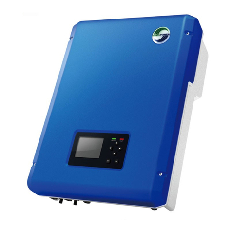
Samil Power SolarLake 5500TL-PM User manual

1

About this Installation Guide .......... 2
Safety Symbols............................... 4
General Safety Requirements ........ 6
Intended Use .................................. 8
Inverter Function........................... 14
Labels and Markings on
the Inverter ................................... 16
Connections on the Inverter ......... 18
User Interface .............................. 20
Unpacking..................................... 22
Mounting the Inverter.................... 24
AC- and DC-Connection ............... 30
Starting the Inverter ...................... 38
Commissioning ............................. 40
Inverter Configuration ................... 48
Opening the Inverter ..................... 50
Accessories .................................. 52
SD Card / Digital Input /
Digital Output ................................ 54
Technical Data .............................. 60
O instrukcji.......... ………………………...2
Symbole bezpieczeństwa................ 4
Wymagania bezpieczeństwa......... ..6
Przeznaczenie urządzenia............... 8
Funkcje inwertera.......................... 14
Etykiety i oznaczenia
inwertera….................................... 16
Połączenia na inwerterze…........... 18
Interfejs użytkownika...................... 20
Rozpakowanie................................ 22
Montażu falownika ……….…………24
Połączenie AC- i DC- ..................... 30
Uruchomienie falownika...................... 38
Rozruch……………............................. 40
Konfiguracja inwertera........................ 48
Otwieranie inwertera........................... 50
Akcesoria ........................................... 52
Karta SD / Wejście cyfrowe/
Wyjście cyfrowe................................ 54
Dane techniczne.............................. 60
Über diese Installationsanleitung ....... 2
Sicherheitszeichen ......................... 4
Allgemeine Sicherheithinweise ....... 6
Bestimmungsgemäßer Gebrauch... 8
Funktionsweise ............................. 14
Hinweise und Symbole auf dem
Wechselrichter .............................. 16
Anschlüsse ................................... 18
Benutzerschnittstelle ................... 20
Auspacken .................................... 22
Montage des Wechselrichters ...... 24
AC- and DC-Anschluss................. ….30
Starten des Wechselrichters ......... 38
Inbetriebnahme............................. 41
Konfiguration ................................ 48
Öffnen des Wechselrichters ......... 50
Zubehör ........................................ 52
SD-Karte / Digitaler Eingang /
Digitaler Ausgang ......................... 54
Technische Daten ......................... 61
Data .............................................. 60
Table of Contents EN
Spis treści PL
Inhaltsverzeichnis DE
2
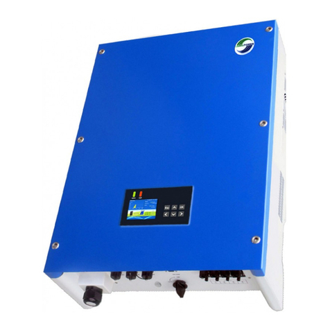
This installation guide describes the
safe installation of the inverters
listed on the left.
Target group:
Qualified technicians
Manufacturer:
Samil Power Co. Ltd.
No.6 Xuefengshan Road,
Suyu District, Suqian,
Jiangsu Province, 214174 P.R.C
Terms:
Installer
Supplier
Inverter
Qualified technician
in charge of the
Installation
Company the product
was purchased from
SolarLake PV-inverter
described in this
installation guide
About this Installation Guide EN
Spis treści PL
Über diese Installationsanleitung DE
Niniejsza instrukcja instalacji opisuje
bezpieczny montaż falowników
wymienionych po lewej stronie.
Target group:
Wykwalifikowani technicy
Producent:
Samil Power Co. Ltd.
No.6 Xuefengshan Road,
Suyu District, Suqian,
Jiangsu Province, 214174 P.R.C
Definicje:
Instalator
Dostawca
Inwerter
Wykwalifikowany technik
odpowiedzialny za instalację.
Firma od której zakupiono produkt
SolarLake PV-inwerter
opisany w niniejszej instrukcji
Diese Installationsanleitung
beschreibt
die sichere Installation der links
aufgeführten Wechselrichter.
Zielgruppe:
Qualifizierter Fachhandwerker
Hersteller:
Samil Power Co. Ltd.
No.6 Xuefengshan Road,
Suyu District, Suqian,
Jiangsu Province, 214174 P.R.C
Terme:
Installateur
Lieferant
Wechsel-
richter
Qualifizierter Fachhandwerker, der
die Installation durchführt.
Firma von der das Produkt bezogen
wurde
SolarLake PV-iWechselrichter, der
in dieser Installationsanleitung
beschrieben wird
3

4
Life threatening voltages are
processed inside the inverter.
Hazardous situations that can lead to
death or serious injuries are indicated
with the “WARNING” symbol (1) on
the left.
Hazardous situations that can result in
damage of the inverter are indicated
with the “CAUTION” symbol (2) on the left.
Countermeasures that must
be taken in order to avoid the
hazardous situation are indicated with
an arrow:
→ “This is an example how to avoid a
hazardous situation.”
Safety Symbols EN
Symbole bezpieczeństwa PL
Sicherheitszeichen DE
Im Wechselrichter werden
lebensgefährliche Spannungen
verarbeitet.
Gefährliche Situationen, die zum Tod
oder schweren Verletzungen führen
können werden mit dem Symbol
“WARNUNG” (1) links angezeigt.
Gefährliche Situationen, die zur
Beschädigung vom Wechselrichter
führen können werden mit dem Symbol
“VORSICHT” (2) links angezeigt
Gegenmaßnahmen zur
Vermeidung der gefährlichen
Situation werden mit einem Pfeil
angezeight:
→ “Dies ist ein Beispiel wie eine
gefährliche Situation vermieden
wird.”
Przetwarzane wewnątrz falownika napięcia
zagrażają życiu.
Niebezpieczne sytuacje, które mogą prowadzić
do śmierci lub poważnych obrażeń są
oznaczone symbolem „OSTRZEŻENIE" (1) po
lewej stronie.
Niebezpieczne sytuacje, które mogą
spowodować uszkodzenia falownika są
oznaczone symbolem "UWAGA" (2) po lewej
stronie. Środki zaradcze, które należy podjąć w
celu uniknięcia sytuacja niebezpiecznej są
oznaczone strzałką: → "To jest przykład, jak
uniknąć niebezpiecznej sytuacji. "

5
1. WARNING! Danger of electric
shock!
→Read Installation Guide
carefully. Follow all
instructions.
2. Contact your supplier when you
have questions.
3. Wear safety shoes when lifting
and transporting.
4. 2 people are required for
lifting and transporting.
WARNING! Danger of electric
shock and fire!
→Never modify the inverter unless
explicitly instructed to do so by the
manufacturer.
Keep this installation guide near the
inverter!
General Safety Requirements EN
Wymagania bezpieczeństwa PL
Grundsätzliche Sicherheitshinweise DE
1. WARNUNG! Gefahr durch
Stromschlag!
→ Lesen Sie die
Installationsanleitung sorgfältig.
Folgen Sie allen Anweisungen.
2. Kontaktieren Sie Ihren Lieferanten,
wenn Sie Fragen haben.
3. Tragen Sie Sicherheitsschuhe wenn
Sie das Gerät tragen oder bewegen.
4. Anheben und Tragen
des Geräts muss durch 2
Personen erfolgen.
WARNUNG! Gefahr durch
Stromschlag und Feuer!
→Jegliche Umbauten des
Wechselrichters sind verboten, es
sei denn, Sie wurden vom Hersteller
dazu angewiesen.
Bewahren Sie diese
Installationsanleitung in der Nähe des
Wechselrichters auf.
1. OSTRZEŻENIE! Niebezpieczeństwo
wstrząsu elektrycznego!
→ Przeczytaj Podręcznik instalacji
ostrożnie. Postępuj zgodnie ze wszystkimi
instrukcjami.
2. W razie pytań, skontaktuj się z
dostawcą.
3. Noś bezpieczne obuwie podczas
podnoszenia i transportu urządzenia.
4. Dwie osoby są potrzebne do
podnoszenia i transportu urządzenia.
OSTRZEŻENIE! Niebezpieczeństwo
porażenia elektrycznego i zagrożenie
pożarem!
→ Nie wolno modyfikować falownika, chyba
że jest to wyraźnie polecenie producenta.
Należy zachować tę podręcznik instalacji w
pobliżu
falownika!

6
The inverter (1) converts DC-power
from the PV-generator (2) to ACpower.
The AC-power is fed into the
Grid (3). In case of a grid failure: The
inverter automatically disconnects
(4) from the grid. The inverter
automatically reconnects when the
grid is restored. The inverter can
only be used for DC-power from
PVgenerators
(5).
CAUTION! Risk of damaging
the inverter!
→Do not connect other DC-power
sources (6) such as wind power
systems, hydroelectric generators,
fuel cells or batteries.
Intended Use EN
Przeznaczenie urządzenia PL
Bestimmungsgemäße Verwendung DE
Der Wechselrichter (1) wandelt
DC-Leistung vom PV-Generator (2) in
AC-Leistung um. Die AC-Leistung wird
ins öffentliche Netz (3) eingespeist.
Im Falle eines Netzausfalls: Der
Wechselrichter trennt sich (4) automatisch
vom Netz. Der Wechselrichter
verbindet sich automatisch wieder mit
dem Netz wenn das Netz wiederhergestellt
ist. Der Wechselrichter kann nur
für DC-Leistung von PV-Generatoren
(5) verwendet werden.
VORSICHT! Gefahr der
Beschädigung des Wechselrichters!
→Andere Quellen für DC-Leistung
(6) wie z.B. Windkraftwerke,
Wasserkraftwerke, Brennstoffzellen
oder Batterien dürfen nicht
angeschlossen werden.
Inwerter (1) przekształca prąd (stały) DC
z generatora-PV (2) na prąd (zmienny) AC.
Prąd zmienny jest doprowadzany do
Sieci (3). W przypadku awarii sieci:
inwerter automatycznie odłącza
(4) się od zasilania . Inwerter
automatycznie łączy się ponownie, gdy
napięcie zostanie przywrócone. Falownik
może być wykorzystywany jedynie do
zasilania prądem DC z instalacji PV
(5). UWAGA! Ryzyko uszkodzenia
inwertera! → Nie należy podłączać innych
źródeł prądu DC (6), takich jak generatory
wiatrowe (turbiny), generatorów elektrowni
wodnych, ogniw paliwowych lub baterii i
akumulatorów.

7
1. WARNING! Risk of electric
shock! The PV-panels emit a
dangerous DC-voltage when
exposed to sunlight.
2. The inverter is not
equipped with an internal
isolation transformer
3. Local regulations and standards
can require that an isolation
transformer is additionally
installed. Contact your utility
operator if you have questions.
Electrical Safety EN
Elektrische Sicherheit DE
1. WARNUNG! Gefahr des
Stromschlags! Die PV-Module
erzeugen eine gefährliche DCSpannung
wenn die Sonne
scheint.
2. Der Wechselrichter hat keinen
Trenntransformator.
3. Die jeweiligen Vorschriften und
Normen können den Einsatz
eines Transformators erforderlich
machen. Fragen Sie Ihren
Netzbetreiber.
Zasady bezpieczeństwa elektrycznego PL
1. UWAGA! Niebezpieczeństwo
szoku elektrycznego! PV-panele emitują
niebezpieczne napięcie DC, gdy
są narażone na działanie promieni
słonecznych.
2. Falownik nie jest
wyposażony w wewnętrzny
transformator izolacyjny
3. Lokalne przepisy i normy
mogą wymagać, aby w izolacji
Transformator został dodatkowo
zainstalowany. Skontaktuj się z
Operatorem sieci w razie pytań.

8
1. Local regulations and standards
can require that current-breakers
are installed on the DC-side.
Contact your utility operator if you
have questions.
2. The inverter is equipped
with an integrated RCMU
Type B (tested according to EN
62109-2 / IEC 60755). If local
regulations and standards require
an external RCD/RCM, a RCD/
RMC Type A is sufficient
DC-Disconnect / RCD EN
DC-Wyłącznik / RCD PL
DC-Trenneinrichtung / RCD DE
1. Die jeweiligen Vorschriften und
Normen können den Einsatz von
Trennschaltern auf der DC-Seite
erforderlich machen. Fragen Sie
Ihren Netzbetreiber.
2. Der Wechselrichter ist mit einem
integrierten RCMU Typ B (geprüft
nach EN 62109-2 / IEC 60755)
ausgestattet. Im Falle das lokale
Vorschriften und Normen die
Installation eines externen RCD/
RCM fordern, ist ein RCD/RCM
Typ A ausreichend.
1. Lokalne przepisy i normy
mogą wymagać, aby obecne wyłączniki
były zainstalowane po stronie prądu stałego.
Skontaktuj się z operatorem sieci w razie
pytań.
2. Inwerter jest wyposażony, w zintegrowany
RCMU Typ B (przetestowane zgodnie z
normą EN 62109-2 / IEC 60755). Jeśli
lokalne przepisy i normy wymagają
zewnętrznego RCD (wyłącznik różnicowy)/
RCM, A RCD /
RMC Typ A jest wystarczający

9
1. DC-side surge voltage protection
2. DC-side insulation monitoring
3. DC-side disconnection switch
(optional)
4. Display, status LEDs, buttons
5. AC-side disconnection relay
6. Grid monitoring
7. AC-side surge voltage protection
8. Digital output port
9. Digital input port
10. Communication extension port
11. Residual Current Device (RCD)
Inverter Function EN
Zasady bezpieczeństwa elektrycznego PL
Funktionsweise des Wechselrichters DE
1. Überspannungsschutz DC-Seite
2. Isolationsüberwachung DC-Seite
3. Trennschalter DC-Seite (optional)
4. Display, Status LEDs, Bedientasten
5. Trennschalter AC-Seite
6. Netzüberwachung
7. Überspannungsschutz AC-Seite
8. Digitaler Ausgang
9. Digitaler Eingang
10. Schacht für optionale
Kommunikation
11. Fehlerstrommessung (RCD)
1. Ogranicznik przepięciowy po stronie DC
2. Monitorowanie stanu izolacji po stronie DC
3. Rozłącznik DC (opcjonalnie)
4. Wyświetlacz, diody LED stanu, przyciski
5. Przekaźniki odłączeniowe po stronie AC
6. Monitorowanie Sieci
7. Ogranicznik przepięciowy po stronie AC
8. Port Wyjścia cyfrowego
9. Port wejścia cyfrowego
10. komunikacyjny Port rozszerzenia
11. Wyłącznik różnicowo-prądowy (RCD)

10
Symbols on Type Label:
General Symbols
1. Ensure proper disposal
2. CE-mark Safety Symbols
3. Read documentation!
4. Warning: Dangerous voltage!
5. Warning: Hot Surfaces!
6. Wait for 5 Minutes before opening!
Markings and Symbols on
bottom of Inverter:
7. AC-plug
8. Opening for relay connection
9. Ethernet connection
10. DC-plug
11. DC-switch (optional)
Periodic Inspection:
Check if all markings and safety
symbols are clearly visible on the
inverter. Replace if necessary.
Labels and Markings on the Inverter EN
Etykiety i oznaczenia na falowniku PL
Hinweise und Symbole auf dem
Wechselrichter DE
Symbole auf dem Typenschild:
Allgemeine Symbole
1. Vorschriftsgemäß entsorgen
2. CE-Zeichen Sicherheitszeichen
3. Installationsanleitung lesen!
4. WARNUNG: Gefährliche Spannung!
5. Warnung: Heiße Oberflächen!
6. Vor dem Öffnen 5 Minuten warten!
Markierungen auf der
Unterseite des Wechselrichters:
7. AC-Stecker
8. Öffnung für Relaisausgang
9. Ethernet Verbindung
10. DC-Stecker
11. DC-Schalter (optional)
Regelmäßige Überprüfung:
Prüfen Sie ob alle Markierungen und
Sicherheitszeichen
auf dem Wechselrichter
deutlich lesbar sind.
Ersetzen Sie fehlende
Markierungen.
Symbole na tabliczce:
Symbole ogólne
1. Zapewnienie właściwej utylizacji
2. znak CE symbol bezpieczeństwa
3. Przeczytaj Dokumentację!
4. Ostrzeżenie: Niebezpieczne napięcie!
5. Ostrzeżenie: Gorące powierzchnie!
6. Odczekaj 5 minut przed otwarciem!
Oznaczenia i symbole na
spodzie Invertera:
7. AC-plug
8. Otwarcie dla połączenia przekaźnika
9. Połączenie Ethernet
10. DC-plug
11. Wyłącznik DC (opcjonalnie)
Przeglądy okresowe:
Sprawdź, czy wszystkie oznaczenia i
symbole bezpieczeństwa są wyraźnie
widoczne na
falowniku. W razie potrzeby wymień.

11
1. DC-switch (optional)
2. DC-plugs
3. Ethernet connector
4. Cable gland for digital input and
digital output
5. Valve for pressure discharge
6. AC-plug
7. Optional communication port
Connections on the Inverter EN
Przyłączenia w inwerterze PL
Verbindungen am Wechselrichter DE
1. DC-Schalter (optional)
2. DC-Stecker
3. Ethernet Buchse
4. Öffnung für digitale Eingänge und
digitale Ausgänge
5. Ventil für Druckausgleich
6. AC-Stecker
7. Schacht für optionale
Kommunikation
1. Rozłącznik DC (opcjonalnie)
2. Wtyczki DC
3. Złącze Ethernet
4. Dławnica do wejścia cyfrowego i wyjście
cyfrowe
5. Zawór do rozładowania ciśnienia
6. Wtyk AC
7. Opcjonalnie port komunikacyjny

12
Green LED
On = Normal operation,
Flashing = Waiting, checking or
starting up, Off = Possible failure
2. Red LED
On = Failure,
Flashing = Temporary failure,
Off = Normal operation
3. ESC-Key
Press ESC-key in order to
exit current screen
4. OK-Key
Press OK-key in order to confirm
entry.
5. Cursor keys
Pressing the cursor keys
navigates the menu and increases
or decreases values.
6. LCD
User Interface EN
Interfejs użytkownika PL
Benutzerschnittstelle DE
1.Grune LED
An = Normaler Betrieb,
Blinkend = Wartend, prüfend oder
startend, Aus = Möglicher Fehler
2. Rote LED
An = Fehler
Blinkend = Vorrübergehender
Fehler
Off = Normaler Betrieb
3. ESC-Taste
ESC-Taste drücken um
momentanen Bildschirm zu
verlassen
4. OK-Taste
OK-Taste drücken um Eingabe zu
bestätigen.
5. Cursor tasten
Drücken der Cursor-Tasten navigiert
durch das Menü und erhöht oder
verringert Werte.
6. LCD
zielona dioda LED
On = normalna praca,
Miga = Oczekiwanie, sprawdzanie lub
uruchamianie, OFF = Możliwa awaria
2. Czerwona dioda LED
On = Failure,
Miga = awaria tymczasowa,
Off = Praca normalna
3. klawisz Esc
Naciśnij klawisz ESC, aby
opuścić bieżący ekran
4. OK-Key
Naciśnij przycisk OK,w celu potwierdzenia
Wprowadzonych danych
5. Klawisze kursora
Naciśnięcie klawiszy kursora pozwala
Poruszać się w menu i zwiększa
lub zmniejszenie wartości.
6. Wyświetlacz LCD

13
Proceed as follows:
•Check the packaging for damages.
•Unpack the inverter and check
if all items of the packing list are included.
•Check all items for visible damages.
Contact your supplier when items are
missing or the inverter is damaged.
Do not install a damaged inverter.
1. Inverter
2. Wall mounting bracket
3. DC-plugs (4 sets)
4. AC-plug
5. Screws for wall mounting
6. Installation guide
7. Quality certificate
8. Cable Gland
9. RJ45
10. Packing List
Keep packaging for later use.
Unpacking EN
Rozpakowanie PL
Auspacken DE
Gehen Sie wie folgt vor:
• Prüfen Sie ob die Verpackung
beschädigt ist.
•Packen Sie den Wechselrichter aus und
prüfen Sie ob alle Bestandteile der
Packliste vorhanden sind.
• Prüfen Sie ob alles unbeschädigt ist.
Kontaktieren Sie Ihren Lieferanten,
wenn etwas fehlt oder etwas
beschädigt ist. Benutzen Sie niemals
einen beschädigten Wechselrichter.
1. Wechselrichter
2. Wandhalterung
3. DC-Stecker (4 Stück)
4. AC-Stecker
5. Schrauben für Wandhalterung
6. Installationsanleitung
7. Quality certificate
8. Kabelverschraubung
9. RJ45
10. Packliste
Bewahren Sie die Verpackung für
spätere Verwendung auf.
Postępuj w następujący sposób:
• Sprawdź opakowanie .
• Rozpakuj falownik i sprawdź
czy wszystkie pozycje na liście opakowania są
włączone.
• Sprawdź wszystkie przedmioty w celu
znalezienia widocznych uszkodzeń.
Skontaktuj się z dostawcą, jeżeli są
brakujące elementy lub falownik jest uszkodzony.
Nie instaluj uszkodzonego falownika.
Zawartość opakowania:
1. Inwerter
2. ścienny uchwyt montażowy
3. DC-wtyczki (4 zestawy)
4. ACwtyczką
5. Śruby do montażu na ścianie
6. Podręcznik do Instalacji
7. Certyfikat jakości
8. Przewód dławik
9. RJ45
10. Lista spakowanych przedmiotów
Zachowaj opakowanie w celu późniejszego
wykorzystania.

14
The following tools are required for
The installation of the inverter:
1. Crimping tool for DC-plugs
(e.g. type PV-CZM)
2. Cable stripping tool for DC-cables
(e.g. PV-AZM)
3. Drill
4. Multimeter
5. Open-end spanner kit for DCplugs
(e.g. PV-MS)
6. Pencil
7. Screwdriver
8. Hammer
9. Level
10. Hex key (2 mm + 4 mm)
Required Tools EN
Potrzebne narzędzia PL
Erforderliches Werkzeug DE
Das folgende Werkzeug ist für die
Installation des Wechselrichter
Efrorderlich:
1. Crimpzange für DC-Stecker
(z.B. PV-CZM)
2. Abisolierzange für DC-Kabel (z.B.
PV-AZM)
3. Bohrmaschine
4. Multimeter
5. Montageschlüssel für DC-Stecker
(z.B. PV-MS)
6. Bleistift
7. Schraubendreher
8. Hammer
9. Wasserwaage
10. Innensechkant (2 mm + 4 mm).
Następujące narzędzia są potrzebne do
Instalacji inwertera:
1. Narzędzie do zaciskania wtyków DC-
(np typu PV-CZM)
2. narzędzie do odizolowywania
przewodów DC (np PV-AZM)
3. Wiertarka
4. Miernik wielofuncyjny
5. klucz do wtyków DC (np PV-MS)
6. Ołówek
7. Śrubokręt
8. Młotek
9. Poziomica
10. Klucz imbusowy (2 mm + 4 mm)

15
Requirements for the installation location are
specified on the following pages.
Proceed as follows:
1. On plasterboard walls: Use center
holes. Screw wall mounting bracket to
wall stud.
2. On massive walls: Use outside holes.
Screw wall mounting bracket to wall.
3. Hang inverter on wall mounting bracket.
4. Check correct position.
5. Optional: Secure the inverter with a
padlock.
Mounting the Inverter EN
Montaż inwertera PL
Montage des Wechselrichters DE
Die Bedingungen an den Montageort
sind auf den folgenden Seiten aufgeführt.
Gehen Sie wie folgt vor:
1. Auf Gipskartonplatten: Mittlere Löcher
benutzen. Wandhalterung auf Lattung
schrauben.
2. Auf massiven Wänden: ÄußLöcher
benutzen. Wandhalterung auf Wand
schrauben.
3. Wechselrichter an Wandhalterung hängen.
4. Auf korrekten Sitz prüfen.
5. Optional: Mit Schloss gegen Diebstahl
sichern.
Wymagania dotyczące miejsca instalacji
podano na następnych stronach.
Należy postępować w następujący sposób:
1. Na ścianach gipsowo-kartonowych:
Wykorzystaj środkowe otwory. Uchwyt
ścienny zamontuj śrubami do ściany.
2. Na mocnych ścianach: Wykorzystaj
otwory zewnętrzne. Uchwyt ścienny
zamontuj śrubami do ściany.
3. Zawiesić falownik na uchwycie
ściennym.
4. Sprawdzić prawidłowe położenie.
5. Opcjonalnie: Zabezpiecz falownik
kłódką.

16

17

18
1. Use 25 A circuit breaker.
2. WARNING! Risk of fire!
→Do not connect any consumers to
the AC- line.
3. Recommendation: Keep cable losses
below
1%. Keep impedance below 2 Ohm.
4. The maximum outer diameter of
the AC- cable is 22 mm. Wire cross
section
2.5 - 4 mm2
5. In France: Use a PE-connection with
a minimum cross.
AC-Connection - Requirements EN
Połączenie AC - Wymagania PL
AC-Anschluss - Voraussetzungen DE
1. Benutzen Sie einen 25 A Der maximale
Aussendurchmesser des AC-Kabels ist
Leitungsschutzschalter.
2. WARNUNG! Gefahr durch Feuer!
→Schließen Sie keine
Verbraucher an die AC-Leitung an.
3. Empfehlung: Halten Sie
Leitungsverluste unter 1 %. Halten
Sie die Impedanz unter 2 Ohm.
4. Der maximale
Aussendurchmesser
des AC-Kabels ist 22 mm. Der
maximale Querschnitt des
Drahtes ist 2,5 - 4 mm2
5. In Frankreich: Benutzen Się eine
PE-Verbindung mit einem Querschnitt
von mindestens 6 mm2 Cu.
1. Użyj wyłącznika 25 A.
2. OSTRZEŻENIE! Zagrożenie pożarowe!
→ Nie należy podłączać żadnych
odbiorników do AC linii.
3. Zalecenie: Zachować straty kablowe
poniżej 1%. Zachowywać impedancję
poniżej 2 omów.
4. Maksymalna średnica zewnętrzna
kabla AC wynosi 22 mm. Przekrój drutu
2,5 - 4 mm2
5. We Francji: Użyj połączenia PE o
minimalnym przekroju.

19
WARNING! Risk of electric shock!
→Deactivate AC-voltage when
connecting the AC-connection
plug.
Proceed as follows:
1. Disconnect voltage.
2. Check that no voltage is present.
3. Prevent accidental reconnection
4 Strip cable as specified in the illustartion
illustration.
5. Remove swivel nut and
shove swivel nut over
cable.
6. Attach wires to AC-plug.
7. Tighten swivel nut.
8. In France: Use an additional
PE-connection with a minimum
cross section of 6 mm2 Cu.
Assembly of the AC-Plug EN
Montaż wtyczki AC PL
Montage des AC-Steckers DE
WARNUNG! Gefahr durch
Stromschlag!
→Schalten Sie die AC-Spannung
ab, bevor Sie den AC-Stecker
montieren.
Gehen Sie wie folgt vor:
1. Spannung abschalten.
2. Stellen Sie die Spannungsfreiheit
sicher.
3. Gegen Wiedereinschalten sichern.
4. Kabel wie beschrieben abisolieren.
5. Überwurfmutter
abschrauben und auf Kabel
schieben.
6. AC-Kabel am AC-Stecker
anschließen.
7. Überwurfmutter festschrauben.
8. In Frankreich: Benutzen Sie
eine zusätzliche PE-Verbindung
mit einem Querschnitt von
mindestens 6 mm2 Cu.
OSTRZEŻENIE! Ryzyko porażenia
prądem!
→ Wyłącz napięcie AC przy
podłączeniu wtyczki AC.
Postępuj w następujący sposób:
1. Odłącz napięcie.
2. Sprawdź, czy nie ma napięcia.
3. Zapobiegaj przypadkowemu
ponownemu załączeniu
4. Odizoluj kabel zgodnie z ilustracją
5. Zdejmij nakrętkę obrotowa i
wepchnij nakrętkę obrotowa na
przewód.
6. Przymocuj przewody do wtyczki AC .
7. Dokręć nakrętkę obrotową.
8. We Francji: Użyj dodatkowego
PE-połączenia z minimalnym
przekrojem 6 mm2 Cu.

20
1. CAUTION! Risk of damaging the
inverter!
→ Ensure that the voltage and
Current is below the specified
values.
2. Do not connect the + or - poles to
ground.
3. The inverter is equipped with two
separate MPP-trackers.
4. The DC-ports can be
Connected: Install diodes
in order to avoid reverse currents.
5. Cover PV-modules when working
on the DC-connection.
6. WARNING! Risk of electric
shock!
→ Do not work on the DC-cables
when the PV-modules are not
covered.
DC-Connection - Requirements EN
Połączenie DC - wymagania PL
DC-Anschluss - Voraussetzungen DE
1. VORSICHT! Gefahr
der Beschädigung des
Wechselrichters!
→Stellen Sie sicher, dass
die Spannung und Strom
unterhalb der angegebenen
Grenzwerte liegen.
2. Schließen Sie die + oder - Pole
nicht an Erde an.
3. Der Wechselrichter ist mit
zwei separaten MPP-Trackern
ausgestattet.
4. Die DC-Anschlüsse
können verbunden
werden. Installieren Sie Dioden
um Rückstrom zu verhindern.
5. Decken Sie die PV-Module ab,
wenn Sie am DC-Anschluss
arbeiten.
6. WARNUNG! Gefahr durch
Stromschlag!
→Arbeiten Sie niemals an den
DC-Kabeln wenn die PVModule
nicht abgedeckt sind.
1. UWAGA! Ryzyko uszkodzenia
inwertera!
→ Upewnij się, że napięcie DC
obecne na modułach jest poniżej określonej
wartości.
2. Nie należy łączyć biegunów + lub – do
uziemienia.
3. Inwerter wyposażony jest w dwa
oddzielne MPP-trackery.
4. Porty DC są gotowe do podłączenia:
Zainstaluj diody w celu eliminacji prądów
wstecznych .
5. Osłoń moduły PV podczas pracy
przy połączeniach DC
6. UWAGA! Ryzyko porażenia prądem
→ Nie pracuj przy-kablach DC
gdy moduły PV nie są osłonięte.
Other manuals for SolarLake 5500TL-PM
2
This manual suits for next models
9
Table of contents
Other Samil Power Inverter manuals

Samil Power
Samil Power SolarRiver 3400TL-D User manual

Samil Power
Samil Power SolarRiver 3400TL-D User manual

Samil Power
Samil Power SolarRiver 1100TL-S User manual

Samil Power
Samil Power SolarLake 5500TL-PM User manual

Samil Power
Samil Power SolarRiver 1100TL Operator's manual

Samil Power
Samil Power SolarRiver 3400TL-D User manual

Samil Power
Samil Power SolarRiver 3400TL-D User manual

Samil Power
Samil Power SolarRiver 4500TL-G3 User manual

Samil Power
Samil Power SolarLake 12000TL-PM User manual

Samil Power
Samil Power SolarLake 5500TL-PM User manual