Samoa Larius Dali Liner Plus Operating instructions

www.larius.com
ED. 14 - 09/2020
Manuale Cod. 150136
DALÌ LINER PLUS
Horizontal street marking
OPERATING AND MAINTENANCE MANUAL
EN

Intentionally blank page

IL VOSTRO PARTNER PER UNA TRACCIATURA IDEALE DAL 1969
Advantages of use
Net and clear lines on any kind of pavement with
one coat only.
With a single coat the line is dened evenly: the line
made by airless spraying is linear, clean-cut and mar-
ked thanks to the at cut nozzle and without the jagged
due to the turbulences caused by air.
Reduction of Over spray.
The airless operated marking guarantees the absence
of the classic "Overspray", that is the dispersion of paint
particles which is typical in the traditional air painting.
This translates, further than in a saving of paint, in a
better protection for health of the operator and for en-
vironment.
Saving of paint up to 30%.
Thanks to the absence of Overspray almost all of the
used product is applied on the surface without any wa-
ste.
Reduction of the vibrations.
The reduction of the vibrations ensures the best in indu-
stry quality of lines.
The paint dries quickly.
The airless operation requires that ltered paint speci-
cally formulated for airless application is used, this me-
ans, by itself, even paint, smooth and uniform texture
which will not return any crust nor will become neither
jelly-like nor thick.
The paint holds tightly on any kind of pavement, with an
excellent visibility and resistance to wear caused both
by trafc and weather elements.
High quality paints guarantee a faster application
speed, a better durability of the visibility of the line and
a pleasant aesthetic result.
Reflective bead application.
Reective beats can be applied using a gravity dispen-
ser operated by the same command which operates
the paint gun. The spheres automatically fall onto the
freshly marked line. No paints with pre-mixed beads
can be used.
50 litre non-stick hopper.
Thanks to the big capacity of the hopper marking times
are extended thanks to the absence of frequent inter-
ruptions to perform colour changes.
Template works and curved marking.
The gun can be released from its support in just a few
seconds and, thanks to the 10 meters pipe it is con-
nected to, it allows any template work, on walls as well.
The front wheel helps to mark lines close to the kerb
and to mark arches and curves.
Intuitive use by the operator.
The operator commands are located right on the
handlebar to adjust the operation of the line marker in
the most handy way.
Optional equipment.
Airless line markers can be equipped basing on the dif-
ferent needs of the operator for offering a dedicated
solution for any marking need.
Easy cleaning and maintenance.
Cleaning airless line markers is quick thanks to the
absence of pressurized tanks to be cleaned and thus
colour change times are extremely short both if using
the can or the non stick paint tank. The high pressure of
the airless line marker clears the spraying area from dirt
and so it does not require that the ground is previously
cleaned.
A regular cleaning at the end of the work is sufcient to
keep the machine in perfect efciency, even after pro-
longed standing periods.
The Larius Super Fast Clean airless nozzles allow that
the nozzle is cleaned with a simple rotating movement,
without any need to detach it.
WELL PROVEN TECHNICAL QUALITY FOR ANY ON-GROUND
MARKING APPLICATION
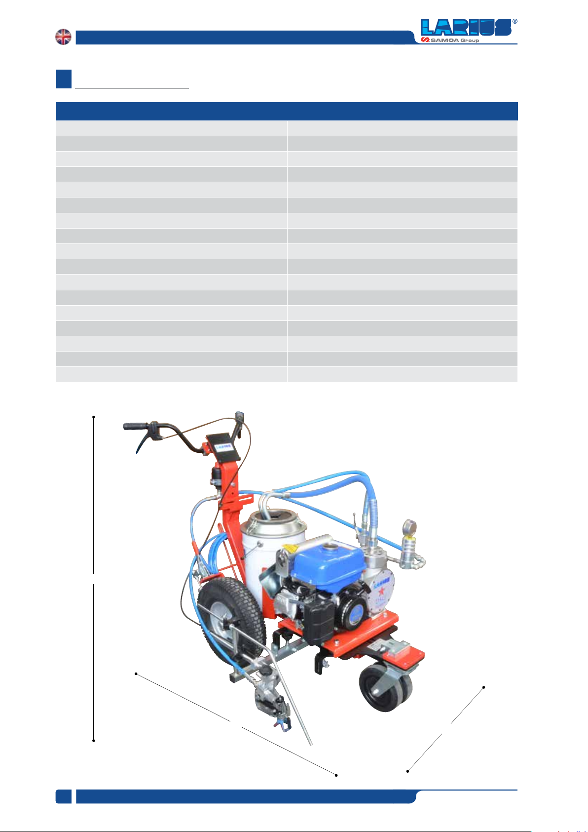
The LARIUS airless line markers successfully join product performan-
ce with operator requirements and allow the marking and the mainte-
nance of any kind of pavement lines on roads, motorways, airports,
pedestrian crossings, cycle paths, yards and wherever is required by
the Highway Code with regards to horizontal road signs, guaranteeing
perfect lines on different surfaces.
The airless technology provides the high pressure spraying of the paint
through a nozzle having centesimal dimensions as compared to the
traditional low pressure spraying in which the paint ow is atomized
through the air contribution.
Larius the ideal choice for achieving
professional performance.

Due to a constant product improvement programme, the factory reserves the right to modify
technical details mentioned in this manual without prior notice.
This manual is to be considered as an English language translation of the original manual in Italian.
The manufacturer shall bear no responsibility for any damages or inconveniences that may arise due to
the incorrect translation of the instructions contained within the original manual in Italian.

www.larius.com
1
DALì LINER PLUS
ED. 14 - 09/2020 - Cod. 150136
DALÌ LINER PLUS
Horizontal street marking
A
C
D
B
E
H
G
F
I
M
N
J
K
L
O
P
Q
R
S
T
U
V
W
X
Y
Z
INDEX
WE ADVISE THE USE OF THIS EQUIPMENT ONLY BY PROFESSIONAL OPERATORS.
ONLY USE THIS MACHINE FOR USAGE SPECIFICALLY MENTIONED IN THIS MANUAL.
Thank you for choosing a LARIUS S.R.L. product.
As well as the product purchased, you will receive a range of support services
enabling you to achieve the results desired, quickly and professionally.
WARNINGS ................................................................................................................................................................. 2
WORKING PRINCIPLE ................................................................................................................................................ 3
TECHNICAL DATA ....................................................................................................................................................... 4
DESCRIPTION OF THE EQUIPMENTA ....................................................................................................................... 6
TRANSPORT AND UNPACKING................................................................................................................................. 9
CONDITIONS OF GUARANTEE .................................................................................................................................. 9
SAFETY RULES........................................................................................................................................................... 9
SETTING-UP ............................................................................................................................................................. 10
REGULATIONS.......................................................................................................................................................... 14
OPERATION............................................................................................................................................................... 15
PAINTING OPERATIONES......................................................................................................................................... 16
CLEANING AT THE END OF WORK.......................................................................................................................... 16
GENERAL MAINTENANCE ........................................................................................................................................17
ROUTINE MAINTENANCE ........................................................................................................................................ 17
CORRECT PROCEDURE OF DECOMPRESSION .................................................................................................... 19
PROBLEMS AND SOLUTIONS ................................................................................................................................. 20
SPARE PARTS .......................................................................................................................................................... 21
COMPLETE HYDRAULIC BODY............................................................................................................................... 22
TRASMISSION UNIT AND POSITIONING................................................................................................................. 26
COMPLETE COLOUR BODY .................................................................................................................................... 27
TANK 50L................................................................................................................................................................... 28
TANK 20L................................................................................................................................................................... 29
COMPLETE FRAME .................................................................................................................................................. 30
COMPLETE STEERING UNIT.................................................................................................................................... 32
FILTER GROUP ......................................................................................................................................................... 33
FLOW COMPENSATOR ............................................................................................................................................ 34
ACCESSORIES.......................................................................................................................................................... 36
CE DECLARATION OF CONFORMITY...................................................................................................................... 39

www.larius.com
2
DALì LINER PLUS
ED. 14 - 09/2020 - Cod. 150136
A
The table below provides the meaning of the symbols used in this manual in relation to using, earthing, operating, maintaining, and
repairing of this equipment.
WARNINGS
A
• Read this operator’s manual carefully before using the equipment.
• An improper use of this machine can cause injuries to people or things.
• Do not use this machine when under the inuence of drugs or alcohol.
• Do not modify the equipment under any circumstances.
• Use products and solvents that are compatible with the various parts of the equipment, and read the manufacturer’s warnings carefully.
• See the Technical Details for the equipment given in the Manual.
• Check the equipment for worn parts once a day. If any worn parts are found, replace them using ONLY original spare parts.
• Keep children and animals away from work area.
• Comply with all safety standards.
• It indicates an accident risk or serious damage to equipment if this warning is not followed.
FIRE AND EXPLOSION HAZARD
• Solvent and paint fumes in work area can ignite or explode.
• To help prevent fire and explosion:
- Use equipment ONLY in well ventilated area.
- Eliminate all ignition sources, such as pilot lights, cigarettes and plastic drop cloths (potential static arc).
- Ground equipment and conductive objects.
- Use only grounded hoses.
- Do not use trichloroethane, methylene chloride, other halogenated hydrocarbon solvents or uids containing such solvents in
pressurized aluminium equipment. Such use can cause serious chemical reaction and equipment rupture, and result in death,
serious injury, and property damage.
- Do not form connections or switch light switches on or off if the air contains inammable fumes.
• If electrical shocks or discharges are encountered the operation being carried out using the equipment must be stopped immediately.
• Keep a re extinguisher at hand in the immediate vicinity of the work area.
• It indicates wound and nger squashing risk due to movable parts in the equipment.
• Tenersi lontano dalle parti in movimento.
• Do not use the equipment without the proper protection.
• Before any inspection or maintenance of the equipment, carry out the decompression procedure explained in this manual, and prevent
any risk of the equipment starting unexpectedly.
• Report any risk of chemical reaction or explosion if this warning has not been given.
• (IF PROVIDED) There is a risk of injury or serious lesion related to contact with the jet from the spray gun. If this should occur, IMME-
DIATELY contact a doctor, indicating the type of product injected.
• (IF PROVIDED) Do not spray before the guard has been placed over the nozzle and the trigger on the spray gun.
• (IF PROVIDED) Do not put your ngers in the spray gun nozzle.
• Once work has been completed, before carrying out any maintenance, complete the decompression procedure.
• It indicates important recommendations about disposal and recycling process of products in accordance with the environmental
regulations.
• Mark any clamps attached to earth cables.
• Use ONLY 3-wire extension cords and grounded electrical outlets.
• Before starting work make sure that the electrical system is grounded and that it complies with safety standards.
• High-pressure uid from gun, hose leaks, or ruptured components will pierce skin.
• To help prevent injection, always:
- (IF PROVIDED) Engage trigger lock when not spraying.
- (IF PROVIDED) Do not put your hand over the spray tip. Do not stop or deect leaks with your hand, body or other.
- (IF PROVIDED) Do not point gun at anyone or at any part of the body.
- (IF PROVIDED) Never spray without tip guard.
- Do pressure relief if you stop spraying or being servicing sprayer and before any maintenance operations.
- Do not use components rated less than sprayer Maximum Working Pressure.
- Never allow children to use this unit
- (IF PROVIDED) Brace yourself; gun may recoil when triggered.
If high pressure fluid pierces your skin, the injury might look like “just a cut”, but it is a serious wound!
Get immediate medical attention.
• It is obligatory to wear suitable clothing as gloves, goggles and face shield.
• Wear clothing that complies with the safety standards in force in the country in which the equipment is used.
• Do not wear bracelets, earrings, rings, chains, or anything else that may hinder the operator’s work.
• Do not wear clothing with wide sleeves, scarves, ties, or any other piece of clothing that could get tangled up in moving parts of the
equipment during the work, inspection, or maintenance cycles.

www.larius.com
3
DALì LINER PLUS
ED. 14 - 09/2020 - Cod. 150136
B
Use water or non-refractive solvent filtered paint
specifically designed for airless application.
In the LARIUS models, the paint canister can be loaded directly
upon the undercarriage or else poured into the non-stick, 50 L
tank. In every case, cleaning, maintenance and colour change
operations are facilitated.
1 2
Fig. 1B
Fig. 2B
SOLID LINE BROKEN LINE
DALì LINER PLUS is ideal for medium marking and maintenance
jobs.
WORKING PRINCIPLE
The DALì LINER PLUS is a self-propelled device which was
conceived and designed for performing road markings along
particularly difcult tracts of uneven road where marking would
otherwise be difcult to complete.
The internal combustion engine, mounted upon the undercarriage,
powers the alternative piston pump and the alternator which is
utilised for charging the battery unit. The two-wheel frontal-traction
is powered by an electric motor which allows for easy operator
movement, even on medium-grade inclines.
The control zone allows for the possibility of:
• Activating the dispensing spray gun;
• Enabling or disabling the frontal steering wheel;
• Increasing the motor’s Rpms;
• Enabling / disabling wheel traction;
• Gradually increasing the advancement speed of the self-
propelled undercarriage;
• Selecting solid or broken-line painting functionality.
This type of equipment is capable of painting one line at a time
in a single color.
The line may be solid or broken.
The paint dries quickly and the line is dened in a uniform manner
with a single coat. The airless function requires the use of ltered
paint which is specically designed for airless application. This
means that the paint is homogeneous, of a smooth and uniform
consistency and will not form crusts, nor will it become gelatinous
or thick. With this airless line-marker, the paint adheres rmly to
all types of pavement, with optimal visibility, and is resistance
to wear caused both by trafc as well as atmospheric agents.
DALì LINER PLUS allows for the marking and maintaining of all
types lines on highways, freeways, pedestrian crossings, parking
lots and squares, as well as every horizontal marking required by
the highway code.
Airless marking has numerous proven benets with respect to
line-markers with pressurised tanks, which have been rendered
obsolete by airless-technology line markers.
Airless line-marking guarantees:
• Decreased Environmental Impact;
• Decreased drying time.
The line-marker is equipped with a 360° pivoting frontal wheel
which even increases the agility of the larger models.
High yield, high efciency, high versatility.
This line-marker utilises non-premixed paints. This allows it to
achieve about 30% more yield with respect to standard line-
markers. Every model is also an airless spray gun which can be
used in the construction/decoration sector together with washable
products, enamels, breathable paints and ooring resins.
A vast assortment of accessories is available to satisfy every
customer demand.

www.larius.com
4
DALì LINER PLUS
ED. 14 - 09/2020 - Cod. 150136
DALì LINER PLUS
Motor power 4 Kw
Max. Delivery 4 - l/m
Max. pressure 210 bar
Airless spray-gun N°1 AT 250
Supply Petrol
Sizes of the furnished nozzles 1 x 11-40 - 1 x 13-40 - 1 x 17-40
50 L tank standard model of ref. 18382
25 L tank standard model of ref. 18383
Colours 1
Automatic line-marking manual
Applications Medium road-marking and maintenance
Multi-use sprayer series
Weight 105 kg
Lenght (A) 1600 mm
Altezza (B) 1100 mm
Width (C) 900 mm
Vibrations Leq(8h)=1.8 m/s2
Fig. 1C
B
A
C
TECHNICAL DATA
C

www.larius.com
5
DALì LINER PLUS
ED. 14 - 09/2020 - Cod. 150136
SECTORS OF USE
• External or underground parking lots (schools, hotels, ai-
rports, supermarkets, train stations, subway stations, ports);
• External public areas;
• Industrial and exhibition building zones;
• Freeway service areas and service stations;
• Pedestrian median lines, intersections, bicycle tracks,
reserved lanes;
• Internal and external logistic area markings;
• Playing elds.
NOZZLES POSITION TABLE
Standard equipment Accessories Models
N°1 Filter with pressure gauge Ref. 18359 Ref. 18382
N°1 High pressure tube 3/16", 10 m Manual gun beads dispenser Dalì Liner Plus 50 lt.
N°1 Recirculation tube
N°1 50 Lt gravity tank + closure valve and extractible filteri Ref. 18383
N°1 Manual airless spray-gun AT250 Ref. 4038 Dalì Liner Plus 20 lt.
N°1 Super fast clean base Laser pointer kit
N°1 Super fast clean nozzle 11-40
N°1 Super fast clean nozzle 13-40
N°1 Super fast clean nozzle 17-40
N°1 Tool pack
N°1 50 Lt gravity tank (Rif. 18382)
N°1 25 Lt gravity tank (Rif. 18383)
Nozzle height from ground 20-degree angle Line Width 40-degree angle Line Width 60-degree angle Line Width
10 cm ~ 3 cm ~ 5 cm ~ 10 cm
15 cm ~ 7 cm ~ 13 cm
20 cm ~ 6 cm ~ 8 cm ~ 16 cm
25 cm ~ 10 cm ~ 20 cm
30 cm ~ 10 cm ~ 12 cm ~ 23 cm
35 cm ~ 26 cm

www.larius.com
6
DALì LINER PLUS
ED. 14 - 09/2020 - Cod. 150136
D
5
Fig. 1D
6
5
4
4
1
2
3
3
6
7
8
9
10
DESCRIPTION OF THE EQUIPMENT
Pos. Description
1 AT 250 gun
2 Spraying gun feeding tube
3 Lock brake safety
4 Flow compensator
5 Lever gun
Pos. Description
6 Lever lock/unlock wheel direction
7 Recirculation tube
8 Tank
9 Manometer high pressure
10 Filter

www.larius.com
7
DALì LINER PLUS
ED. 14 - 09/2020 - Cod. 150136
Fig. 2D
16
14
13
13
12
16
17
18
15
19
11
Pos. Description
11 Product feeding tube
12 Petrol tank
13 Rope starter motor
14 Pumping group
15 Combustion engine
Pos. Description
16 Air cold starting
17 Air filter
18 Oil level cap combustion engine
19 Rotating wheel

www.larius.com
8
DALì LINER PLUS
ED. 14 - 09/2020 - Cod. 150136
22
20
21
23
24
25
Fig. 3D
26 27 28
29
Pos. Description
20 Fuel tap OPEN/CLOSE
21 Spraying gun feeding tube
22 Oil level light hydraulic body
23 Belt tensioning screw
24 ON - OFF switch combustion engine
Pos. Description
25 Accelerator lever
26 Cooling fan
27 Transmission belt pumping group
28 Driving pulley
29 Free pulley

www.larius.com
9
DALì LINER PLUS
ED. 14 - 09/2020 - Cod. 150136
E
F
G
The disposal of packaging materials is a custo-
mer’s competence and must be performed in
accordance with the regulations in force in the
country where the plant is installed and used
.
It is nevertheless sound practice to recycle
packaging materials in an environment-friendly
manner as much as possible.
• The packed parts should be handled as indicated in the
symbols and markings on the outside of the packing.
• Before installing the equipment, ensure that the area to be
used is large enough for such purposes, is properly lit and
has a clean, smooth oor surface.
• The user is responsible for the operations of unloading and
handling and should use the maximum care so as not to
damage the individual parts or injure anyone.
To perform the unloading operation, use only qualied and
trained personnel (truck and crane operators, etc.) and also
suitable hoisting equipment for the weight of the installation
or its parts. Follow carefully all the safety rules.
The personnel must be equipped with the necessary safety
clothing.
• The manufacturer will not be responsible for the unloading
operations and transport to the workplace of the machine.
• Check the packing is undamaged on receipt of the equipment.
Unpack the machine and verify if there has been any damage
due to transportation.
In case of damage, call immediately LARIUS and the Shipping
Agent.
All the notices about possible damage or anomalies must
arrive timely within 8 days at least from the date of receipt
of the plant through Registered Letter to the Shipping Agent
and to LARIUS.
TRANSPORT AND UNPACKING
The conditions of guarantee do not apply in the
following situations:
- improper washing and cleaning of components
causing malfunction, wear or damage to the
equipment or any of its parts;
- improper use of the equipment;
- use that does not conform with applicable na-
tional legislation;
- incorrect or faulty installation;
- modifications, interventions and maintenance
that have not been authorised by the manu-
facturer;
- use of non-original spare parts or parts that do
not correspond to the specific model;
- total or partial non-compliance with the instruc-
tions provided.
CONDITIONS OF GUARANTEE
SAFETY RULES
•THE EMPLOYER SHALL TRAIN ITS EMPLOYEES ABOUT
ALL THOSE RISKS STEMMING FROM ACCIDENTS, ABOUT
THE USE OF SAFETY DEVICES FOR THEIR OWN SAFE-
TY AND ABOUT THE GENERAL RULES FOR ACCIDENT
PREVENTION IN COMPLIANCE WITH INTERNATIONAL
REGULATIONS AND WITH THE LAWS OF THE COUNTRY
WHERE THE PLANT IS USED.
•THE BEHAVIOUR OF THE EMPLOYEES SHALL STRICTLY
COMPLY WITH THE ACCIDENT PREVENTION AND ALSO
ENVIRONMENTAL REGULATIONS IN FORCE IN THE
COUNTRY WHERE THE PLANT IS INSTALLED AND USED.
• KEEP YOUR WORK PLACE CLEAN AND TIDY. DISORDER
WHERE YOU ARE WORKING CREATES A POTENTIAL RISK
OF ACCIDENTS.
• ALWAYS KEEP PROPER BALANCE AVOIDING UNUSUAL
STANCE.
• BEFORE USING THE TOOL, ENSURE THERE ARE NOT
DAMAGED PARTS AND THE MACHINE CAN WORK PRO-
PERLY.
• ALWAYS FOLLOW THE INSTRUCTIONS ABOUT SAFETY
AND THE REGULATIONS IN FORCE.
• KEEP THOSE WHO ARE NOT RESPONSIBLE FOR THE
EQUIPMENT OUT OF THE WORK AREA..
• NEVER EXCEED THE MAXIMUM WORKING PRESSURE
INDICATED.
• NEVER POINT THE SPRAY GUN AT YOURSELVES OR AT
OTHER PEOPLE. THE CONTACT WITH THE CASTING CAN
CAUSE SERIOUS INJURIES.
• IN CASE OF INJURIES CAUSED BY THE GUN CASTING,
SEEK IMMEDIATE MEDICAL ADVICE SPECIFYING THE
TYPE OF THE PRODUCT INJECTED. NEVER UNDERVALUE
A WOUND CAUSED BY THE INJECTION OF A FLUID.
• ALWAYS DISCONNECT THE SUPPLY AND RELEASE THE
PRESSURE IN THE CIRCUIT BEFORE PERFORMING ANY
CHECK OR PART REPLACEMENT OF THE EQUIPMENT.
• NEVER MODIFY ANY PART IN THE EQUIPMENT. CHECK
REGULARLY THE COMPONENTS OF THE SYSTEM. RE-
PLACE THE PARTS DAMAGED OR WORN.
Read carefully and entirely the following instruc-
tions before using the product.
Please save these instructions in a safe place.
The unauthorised tampering/replacement of one
or more parts composing the machine, the use
of accessories, tools, expendable materials other
than those recommended by the manufacturer
can be a danger of accident.
The manufacturer will be relieved from tort and
criminal liability.

www.larius.com
10
DALì LINER PLUS
ED. 14 - 09/2020 - Cod. 150136
H
Fig. 1H
H1
H2
Fig. 2H
H3
H4
• TIGHTEN AND CHECK ALL THE FITTINGS FOR CONNEC-
TION BETWEEN PUMP, FLEXIBLE HOSE AND SPRAY GUN
BEFORE USING THE EQUIPMENT.
• ALWAYS USE THE FLEXIBLE HOSE SUPPLIED WITH STAN-
DARD KIT. THE USE OF ANY ACCESSORIES OR TOOLING
OTHER THAN THOSE RECOMMENDED IN THIS MANUAL,
MAY CAUSE DAMAGE OR INJURE THE OPERATOR.
• THE FLUID CONTAINED IN THE FLEXIBLE HOSE CAN BE
VERY DANGEROUS. HANDLE THE FLEXIBLE HOSE CARE-
FULLY. DO NOT PULL THE FLEXIBLE HOSE TO MOVE THE
EQUIPMENT. NEVER USE A DAMAGED OR A REPAIRED
FLEXIBLE HOSE.
• NEVER SPRAY OVER FLAMMABLE PRODUCTS OR SOL-
VENTS IN CLOSED PLACES.
• NEVER USE THE TOOLING IN PRESENCE OF POTENTIALLY
EXPLOSIVE GAS.
Pump unit flexible tube connection
• Connect the product suction exible tube (H3) to the connector
(H4) ensuring to tighten the ttings (the use of two wrenches
is suggested).
The high speed of the product in the hose can
create static electricity through discharges and
sparks.
It is suggested to earth the equipment.
The pump is earthed through the earth cable of
the supply. The gun is earthed through the high
pressure flexible hose. All the conductors near
the work area must be earthed.
Always check the product is compatible with the
materials composing the equipment (pump, spray
gun, flexible hose and accessories) with which it
can come into contact.
If the product to be used is toxic, avoid inha-
lation and contact by using protection gloves,
goggles and proper face shields.
Take proper safety measures for the protection
of hearing in case of work near the plant.
Engine safety precautions:
• Read the engine operator's manual annex.
Never attempt to tamper with the calibre of
instruments.
SETTING-UP
TUBE CONNECTIONS
Flexible re-circulation tube connection
•
Connect the exible re-circulation tube (H1) to the connector
(H2) ensuring to tighten the ttings (the use of two wrenches
is suggested).

www.larius.com
11
DALì LINER PLUS
ED. 14 - 09/2020 - Cod. 150136
Fig. 3H
H5
H6
H5
Fig. 4H
H7
Fig. 5H
FUEL
H8
Fig. 6H
H9
Fig. 7H
H10
STARTING THE COMBUSTION ENGINE
To switch the internal combustion engine proceed as follows:
• Fill the fuel tank (H8).
• Open the fuel tap (H9) and position it to “ON” (I).
• Pull lever (H10) for rst start-up cold (position it to “I”).
CONNECTION OF THE GUN
• Connect the high pressure exible hose (H5) to the tting (H6)
and the gun (H7) tightening the ttings strongly (the use of
two wrenches is suggested).
NEVER use sealants on ttings’ threads.
• It is recommended to use the hose provided with the standard
kit.
NEVER use a damaged or a repaired exible hose.

www.larius.com
12
DALì LINER PLUS
ED. 14 - 09/2020 - Cod. 150136
Fig. 8H
H11
Fig. 9H
H12
1/2
Fig. 10H
Fig. 11H
H18
Fig. 12H
H14
Fig. 13H
H15
• Fill the product tank with wash uid.
• Clean the inside of the tank with a brush.
• Bring the accelerator lever (H12) to about 1/2 of its run.
•
Pull the rope to start (H13).
• Open the product output tap (H15).
• Ensure the gun (H14) is without nozzle.
WASHING OF THE NEW EQUIPMENT
• The equipment has already been adjusted at our factory with
light mineral oil left inside the pumping group as protection.
Therefore, wash with diluent before sucking the product.
• Turn the equipment’s switch (H11) to ON (I).
Version 50L

www.larius.com
13
DALì LINER PLUS
ED. 14 - 09/2020 - Cod. 150136
Fig. 14H
H16
Fig. 15H
H17
Fig. 16H
H18
Fig. 17H
H16
H14
H19
Fig. 18H
• Open the recirculating-safety valve (H16).
• Visually check that the wash uid starts to re-circulate within
the tank (H18).
• Once the wash uid has circulating enough, close the
recirculating-safety valve (H16).
• Remove the gun (H14) from its support and point it into a
container (H19). Hold the trigger down (to perform the cle-
aning) until clean solvent comes out, or else until all of the
wash uid has been expelled from the tank.
• After having completed the wash operations, bring the handle
to its MIN position (H17) and point the gun (H14) into a col-
lection container (H19) and press the trigger to release the
residual pressure. Release the trigger when nished.
OPEN
• Start the combustion engine following the indications provided
in the chapter “STARTING COMBUSTION ENGINE”.
• Rotate the pressure setting knob (H17) slightly clockwise so
that the machine operates at minimum power.
CLOSE
Repeat the same operations with clean solvent
if necessary.
NEVER spray solvents indoors. In addition, it is
recommended to keep away from the pump in
order to avoid the contact between the solvent
fumes and the motor.

www.larius.com
14
DALì LINER PLUS
ED. 14 - 09/2020 - Cod. 150136
I
Fig. 19H
H20
Fig. 1I
I2I3
I1
Fig. 2I
I4
I5
I5I4
• When the pump idles stop the combustion engine.
• At this point the machine is ready. If water-based paints are
to be used, after the wash with solvent wash the tank again
with soap and water, then rinse with clean water (repeating
the previously described procedures).
• Insert the manual gun trigger lock and assemble the nozzle.
MAKE SURE THE PRODUCT IS SUITABLE TO BE
USED WITH A SPRAY GUN.
Make sure the product to be used is compatible
with the materials employed for manufacturing
the equipment (stainless steel and aluminium).
Because of that, please contact the supplier of
the product
.
REGULATIONS
• Mix and lter the product before using it. For ltration use
CLOSE-MESH (rif. 214) and LARGE-MESH (rif. 215) LARIUS
METEX braids.
PRODUCT PREPARATION
Never use products containing halogen hydrocarbons (as methyle-
ne chloride). If these products come into contact with aluminium
parts of the equipment, can provoke dangerous chemical reactions
with risk of explosion.
• Fill the tank (H20) with the paint.
ADJUSTING THE GUN POSITION
In order to adjust the position of the spray gun (I1) use the knobs
(I2-I3).
ADJUSTING THE GUN SUPPORT ARM
In order to adjust the position of the spray gun (I4) use the knobs (I5).

www.larius.com
15
DALì LINER PLUS
ED. 14 - 09/2020 - Cod. 150136
J
Fig. 3I
I6
Fig. 4I
I7
I8I9 I7 I7
Fig. 1J J1
Fig. 2J
J2
Fig. 3J
J3
Fig. 4J
J4
OPERATION
• Start the combustion engine following the indications provided
in the chapter “STARTING COMBUSTION ENGINE”.
• Make sure that the re-circulation/safety valve (J3) is closed
(spray enabled).
ADJUSTING BELT TENSION
To adjust the belt tension (I6) you need to follow the following
procedure:
• Unscrew the 4 screws (I7).
• Unscrew the locknut (I8).
• Turn the screw (I9) to make the adjustment.
• Turn the equipment knob (J2) on ON (I).
• Turn the pressure (J4) adjustment handle clockwise until the
desired setting has been reached.
SETUP PROCEDURE
• Use the tooling after performing all the SETTING UP ope-
rations above described.
• Check that there is enough unleaded petrol.
• Open the product output tap (J1).
Version 50L

www.larius.com
16
DALì LINER PLUS
ED. 14 - 09/2020 - Cod. 150136
K
L
Fig. 5J
3/4
Fig. 1K
K1
Fig. 2K
K2
Fig. 1L
L1
Fig. 2L
L4L3L2
PAINTING OPERATIONES
After having performed all of the operations in the “OPERATION”
chapter, work may be started using the following controls:
• Turn the pressure adjustment handle (K1) clockwise to allow
the line-painting gun to dispense paint when the appropriate
lever is activated.
NEVER point the spray gun at yourselves or at
other people. The contact with the casting can
use serious injuries. In case of injuries caused by
the gun casting, seek immediate medical advice
specifying the type of the product injected.
CLEANING AT THE END OF
WORK
• Reduce pressure to the minimum (turn counterclockwise the
pressure control knob (L1)).
ADJUSTING PUMP UNIT SPEED
• Move the motor acceleration lever (J5) gently to increase or
decrease the speed of the pump.
During the painting operation it is normally recommended to
maintain the position of the accelerator lever (J5) at about 3/4 of
its maximum run.
• An irregular and marked spray on the sides indicates a low
working pressure. On the contrary, a too high pressure causes
a high fog (“overspray”) and waste of product.
• Pull the lever on the right (K2) to activate the spray gun
and begin working, advancing the machine in a continuous
manner.
• Release the residual pressure by holding down the trigger
of the gun and pointing it into a container.
• Eliminate the paint remaining within the tank (L2) by placing
the re-circulation tube (L3) into a container.
• Open the recirculating-safety valve (L4).
Recirculating-safety valve: when working at the
maximum pressure available, releasing the gun
trigger sudden increases of pressure can occur. In
this case, the recirculating-safety (J2) valve opens
automatically eliminating part of the product from
the recirculating tube (J5).
Then it closes so as to go back to the first wor-
king conditions.
Table of contents
Other Samoa Construction Equipment manuals