Samon ONION LOADER SU2LS User manual

Dealer:
Ploegstraat 4 ◼8308 AA Nagele ◼The Netherlands ◼Tel. +31 (0)527 –652 500
Fax +31 (0)527 –652 916 ◼www.samon.nl ◼info@samon.nl
SAMON
ONION LOADER
Manual and Parts list
Type:
SU2LS
V1-2018-ENG

Contents.
1. Introduction. ............................................................................................................................................1
2. Warranty an liability.................................................................................................................................2
2.1 Warranty................................................................................................................................................ 2
2.2 Liability. ................................................................................................................................................. 2
3. Safety and Environment. .......................................................................................................................... 3
3.1 General safety........................................................................................................................................ 3
3.2 Environment. ......................................................................................................................................... 3
3.3 Warning labels and pictograms. ............................................................................................................ 4
4. Inspections before and during use............................................................................................................5
4.1 Necessary inspections before using the SU2LS for the first time.......................................................... 5
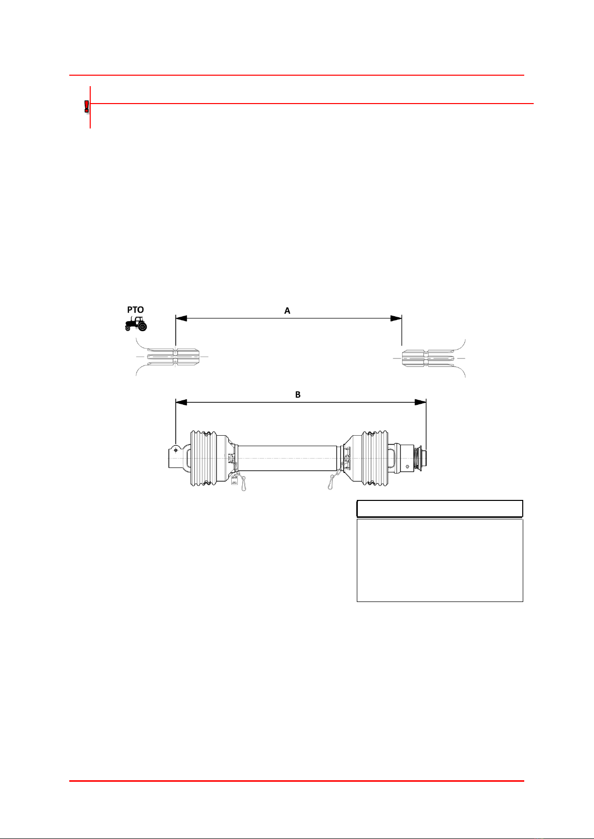
4.2 Shortening the PTO shaft. ..................................................................................................................... 5
4.3 Necessary inspections before each use................................................................................................. 6
4.3 Inspections during use........................................................................................................................... 6
5. Operation................................................................................................................................................. 7
5.1 Connecting and disconnecting the SAMON onion loader. .................................................................... 7
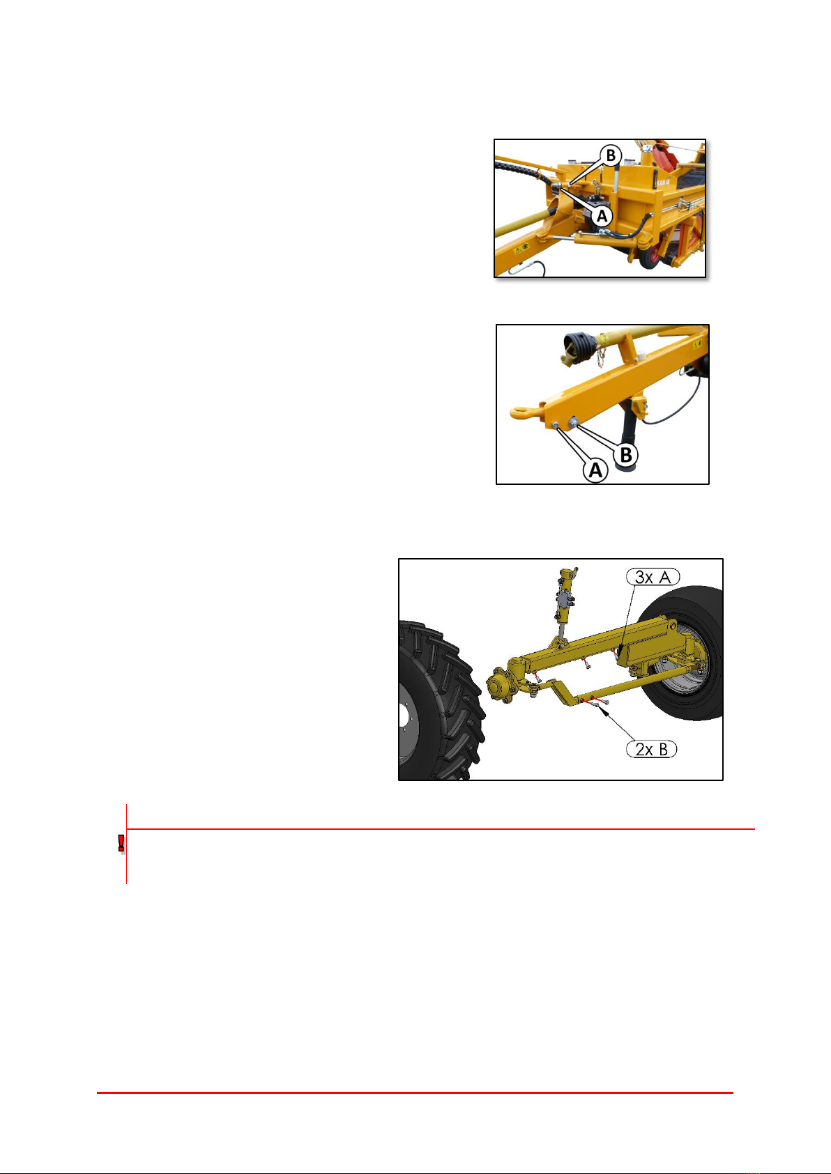
5.2 Adjusting the drawbar........................................................................................................................... 8
5.3 Adjusting the wheel track...................................................................................................................... 8
5.4 Remote control...................................................................................................................................... 9
5.5 Operating the discharge conveyor. ..................................................................................................... 10
5.6 Intake................................................................................................................................................... 13
5.7 Operating the sieving belts.................................................................................................................. 14
5.8 Steering................................................................................................................................................ 14
5.9 Hedgehog belt. .................................................................................................................................... 15
5.10 Leveling................................................................................................................................................ 16
6. Maintenance. ......................................................................................................................................... 17
6.1 Lubrication schedule............................................................................................................................ 17
6.2 Level and temperature of the hydraulic oil. ........................................................................................ 19
6.3 Replacing the gearbox oil. ................................................................................................................... 19
7. Transport and storage. ........................................................................................................................... 20
7.1 Transport on a vehicle. ........................................................................................................................ 20
7.2 Transport behind a tractor. ................................................................................................................. 20
7.3 Storage................................................................................................................................................. 20
8. Technical information and diagrams....................................................................................................... 21
8.2 Technical information.......................................................................................................................... 21
8.1 Hydraulic diagram of hydraulic motors. .............................................................................................. 21
8.2 Hydraulic diagram of hydraulic cylinders ............................................................................................ 22
8.3 Electric diagram for remote control .................................................................................................... 23
8.4 Electric diagram for main cabinet........................................................................................................ 24
9. Ordering parts. ....................................................................................................................................... 25
10. Troubleshooting. .................................................................................................................................... 26
11. EG Declaration of Conformity................................................................................................................. 27

H1
V1-2018-ENG
20
1. Introduction.
This user’s manual and part list is intended for buyers of a SAMON SU2LS onion loader. It contains information
about the use and maintenance of this machine.
When this guide was compiled the utmost care was taken to ensure that the illustrations and technical data re
correct and up to date.
Ellens Landbouwtechniek B.V. recommends that users read this manual carefully before using the machine and
observe the manual's instructions, directions and comments.
References to the left or right side of the machine are determined based on the direction in which the machine
is driven.
Ellens Landbouwtechniek BV reserves the right to amend the contents of this manual without notice.
This machine was designed in accordance with the provisions of the Machinery Directive 89/392/EEC +
amendments.

H2
V1-2018-ENG
20
2. Warranty and liability
2.1 Warranty.
SAMON agricultural machinery is covered by a 1-season warranty. The SAMON Onion Loader is designed and
intended for use to load onions. * Use of the SAMON Onion Loader for purposes other than for which it is
intended is regarded as improper use.
* Always check with your Samon dealer before using the machine for other types of tops and crops.
This warranty is issued for construction defects in the machine that occur during normal use. Parts which are
subject to wear are not covered by this warranty, namely:
•Chain wheels, chains, tensioning wheels, guide wheels,
•Sieve belts,
•Bearings,
•Shares,
•other parts subject to wear.
The Warranty on hydraulic components, PTO shafts, and gearboxes covers solely construction defects of the
components that result in their failure as assessed by the manufacturer. This warranty lapses in the event of:
•Structural modifications and changes to the machine without permission from Ellens
Landbouwtechniek BV.
•Installation and use of components on or attached to the SAMON Onion Loader that are detrimental
to the rigidity of the structure.
•Failure of components due to the non-observance of maintenance intervals.
•Changing or ignoring the specified settings and adjustments that could result in damage.
Our dealers and manufacturer's service points will be pleased to provide you information and assistance.
2.2 Liability.
Ellens Landbouwtechniek BV is not liable for damage to SAMON agricultural machinery, tractors, third-party
machines, injury to persons or animals or damage to products caused by:
•improper use.
•failure to observe the instructions and directions stated in the manual.

H3
V1-2018-ENG
20
3. Safety and Environment.
3.1 General safety.
NOTE!!!
Make sure that all persons who work with and/or service the SAMON onion Loader have read this manual
and take the necessary precautions to protect their safety and the safety of others when they work with
the SAMON onion Loader.
Always bear the following points in mind when working with or on the SAMON onion loader.
•The SAMON Onion Loader may be operated, serviced and maintained solely by persons who are
familiar with the machine and with the necessary safety procedures.
•Always switch off the tractor's engine and remove the key from the ignition before carrying out
inspections of or maintenance on the SAMON Onion Loader.
•The SAMON Onion Loader contains moving sieve and conveyor belts that can trap body parts.
•For this reason, never come close to a SAMON Onion Loader while it is in operation.
•Always wait until the sieve and conveyor belts have stopped moving before approaching the machine.
•A hedgehog belt mounted at the back of the SAMON Onion Loader unloads foreign matter. Never
come close to the hedgehog belt while it is working.
•If the machine hits an object, then switch off the SAMON Onion Loader and inspect the machine for
damage before switching it on again.
•The SAMON Onion Loader contains several parts which are fitted with locking pins and safety cords
and/or chains. These must always be fitted to the machine.
•Damaged and broken safeguards and locking devices must be replaced immediately.
•Protective covers, sleeves and rubber flaps may never be damaged. Always replace them when they
are dented or cracked.
•Always use original SAMON parts: these are designed specifically for the Onion Loader.
3.2 Environment.
Protect the environment by always cleaning and servicing the SAMON Onion Loader on a hard, impermeable
floor.
NOTE!!!
Dispose of spent lubricant in an environmentally-friendly manner. We recommend that you collect spent
oil in a closed container and deliver the oil to a recycling center or a collection point. Never dispose of
spent oil by allowing it to run off into a ditch, drain, sewer or the soil.

H4
V1-2018-ENG
20
3.3 Warning labels and pictograms.
All SAMON Onion Loaders display the following labels and warning pictograms:
Description:
Dimensions: (wxh)
Order no.
A:
“Samon” sticker
24,8 x 7,8
TL6304
B:
“Watch out for your hand/foot” sticker
19,3 x 6,4
TL6309
C:
“Check the manual” sticker
13,3 x 6,4
TL6310
If any of these stickers is missing or illegible then you can order a replacement from your SAMON dealer.

H5
V1-2018-ENG
20
4. Inspections before and during use.
WARNING!!!
Make sure that the tractor's engine has been switched off and the key has been removed from the ignition
before you carry out inspections of or maintenance on the SAMON Onion Loader.
4.1 Necessary inspections before using the SU2LS for the first time
•Make sure all steps from chapter 5 are carefully followed up.
•Check the length of the PTO shaft (see 4.2)
•Check that all the wheel nuts are properly fixed. Always tighten the wheel nuts with a big cross-
key. Tighten the wheel nuts again after using the machine for two hours. Repeat this step each
time a wheel has been disassembled.
•Check all points of 4.3.
4.2 Shortening the PTO shaft.
When the inspection before use reveals that the PTO shaft is too long then it can be shortened as follows:
•Connect the machine to the tractor.
•Position the PTO shafts so that they are as close as
possible to each other.
•Measure distance "A" of the PTO shafts.
•Measure distance "B" of the PTO shafts
(see the illustration for the measuring points).
•Subtract length "A" from length "B" and add 10mm.
•Shorten the PTO shaft by the result (see example).
Example of a calcuation:
A=400 mm
B=450 mm
B(450) - A(400) = 50 + 10
To be shorened by 60 mm

H6
V1-2018-ENG
20
4.3 Necessary inspections before each use.
•Check that the machine is correctly connected to the tractor as explained in chapter 5.
•Check that the return of the machine is connected to a pressure-free return of the tractor (see
5.1.1).
•Inspect the tow-ring for damage.
•Inspect the lighting and reflectors for damage.
•Check the oil level of the oil tanks (see 6.2)
•Inspect the gearbox for leaks.
•Inspect the complete hydraulic system for leaks.
•Inspect the electronics for damage.
•Inspect the tyres for damage and check the tyre pressure (2.5 bar).
•Inspect the protective cover of the PTO shaft for cracks.
•Check that the safety chains of the PTO shaft are fitted.
•Check that the locking clips and safety cords are in place.
•Inspect all protective covers for damage.
•Inspect the sieve, hedgehog and conveyor belts for damage and wear.
•Inspect drive and guide wheels for wear.
•Check that the wheel’s locking bolts are tight.
•Check that the conveyor belt is neatly between the flanges of the rollers (see 5.5.4).
4.3 Inspections during use.
•Check that the intake is at the right depth: it should enter the soil to a depth of 1 á 2 cm. If the
onion loader is equipped with a rotating bar the rotating bar should be in the soil for about ¾ (see
5.6.2)
•Check to make sure that the onions are not damaged.
•Check the adjustment of the hedgehog belt (see 5.7).
•Check the wheel track (see 5.2).
•Check that the intake plates are adjusted correctly.
WARNING!!!
The speed at which wearing parts wear depends on the type of soil. For this reason, the wearing parts
need to be inspected regularly to avoid damage to the SAMON Onion Loader.

H7
V1-2018-ENG
20
5. Operation.
WARNING!!!
Always use a pressure-free return. The male quick-fit coupling on the machine is the pressure side and the
female quick-fit coupling on the machine is the return side
5.1 Connecting and disconnecting the SAMON onion loader.
Connecting
•Open valve (C) (lever in the same direction as the
tube).
•Close button (B) (turn clockwise).
•Move lever (A) until the tow-ring is higher than the
towbar of the tractor.
•Move the tractor so that the towbar is exactly under
the tow-ring.
•Open (B) (turn anticlockwise) to lower the machine.
•Check that the tow-ring is correctly connected and
locked.
•Fold the support leg and lock it with the locking pins.
•Fit the PTO shaft (540 PTO.).
•Fasten the PTO shaft protective cover safety chains
•Put the remote control in the tractor.
Disconnecting
•Remove all the electrical wires and hydraulic tubes
from the tractor.
•Unfold the support leg and lock it with the locking
pins.
•Close button (B) (turn clockwise) and move lever (A)
until the tow-ring releases the towbar.
•Close valve (C) (lever perpendicular to the tube).
5.1.1 Connecting the hydraulic hoses, lighting plug and the power plug.
Connect the hydraulic hoses using the quick-fit couplings.
•The male quick-fit coupling (M) is the pressure side.
•The female quick-fit coupling (V) is the return side.
•Adjust the oil flow of the tractor to 25 l/min.
NOTE! Always connect the return on a pressure-free
return of the tractor.
•Connect the lighting plug (A)
•Connect the power plug (B)
NOTE! Make sure that the power is 12V.

H8
V1-2018-ENG
20
5.2 Adjusting the drawbar.
5.2.1 Adjusting drawbar height.
The height of the drawbar can be adjusted to the height of the
towbar of the tractor.
•Loosen lock nut (A).
•Adjust drawbar height with nut (B).
•Tighten lock nut (A).
5.2.2 Adjusting tow-ring.
In order to have the tow-ring parallel to the towbar of the
tractor the tow-ring also needs to be adjusted when the height
of the drawbar is adjusted.
•Loosen lock nuts (A) and (B) and adjust the angle of
the tow-ring.
•Tighten lock nuts (A) and (B).
5.3 Adjusting the wheel track.
Adjusting the wheel track:
•Lift the machine until the right wheel is
free from the ground.
•Loosen locking bolts (A) and (B).
•Adjust the wheel to the right track.
•Tighten all the locking bolts. Make sure
that the locking bolts (B) fall into the
holes of the steering axle.
Check that all five the locking bolts are used.
WARNING!!!
Always use all the locking bolts. Check that the wheel is not to pulled out to far! Always observe the
prevailing traffic regulations with regard to the maximum width when the machine is being transported on
public roads.

H9
V1-2018-ENG
20
5.4 Remote control.
The remote control needs to be operated within the tractor. When the SU2LS onion loader is stationary for a
long time, disconnect the remote control and store it in a dry place.
Nr.:
Type:
Function:
1
Light
Power on/off indicator.
2
Switch
Power on/off.
3
Switch
Lights on/off.
4
Switch
Discharge conveyer belt on/off.
5
Potentiometer
Speed conveyer belt.
6
Joystick
Adjusting hedgehog belt / adjusting angle of machine.
7
Push button
Putting the wheels straight.
8
Joystick
Operating intake.
9
Switch
Selecting which part of the discharge conveyor should fold
or unfold.
10
Joystick
Folding and unfolding conveyor belt.
11
Joystick
Adjust angle of drawbar / steering the wheels.

H10
V1-2018-ENG
20
5.5 Operating the discharge conveyor.
The SAMON onion loader is equipped with a discharge conveyor belt to load the onions into a tipper. The
electronic remote control is used to operate the conveyor belt. The drive has an infinitely-variable speed
controller and the conveyor can be folded in for transport.
5.5.1 Folding the conveyor belt in and out.
WARNING!!!
Never switch on the conveyor belt when the conveyor folded in.
Never transport a SAMON onion loader with the conveyor belt folded out.
Carefully follow up the instructions for folding the conveyor belt in and out. Ignoring these instructions can
cause damage to the machine.
Three cylinders/ cylinder groups are used to fold and unfold the discharge conveyor.
H: Main cylinder: controlled by moving joystick 10 left/right (while having switch 9 in bottom position).
K: Middle part cylinder: controlled by moving joystick 10 left/right (while having switch 9 in upper position).
T: Top part cylinders: controlled by moving joystick 10 up/down.

H11
V1-2018-ENG
20
The conveyor belt should be folded out as follows.
Operation
Machine
Starting with a totally folded
conveyor.
Step 1.
Maximally extend the main
cylinder.
Put switch 9 in bottom position
and move joystick 10 to the
left.
Step 2.
Maximally extend the middle
part cylinder.
Put switch 9 in upper position
and move joystick 10 to the
left. When finished move
switch 9 back in bottom
position (this is the working
position).
Step 3.
Unfold the top part.
Move joystick 10 up.

H12
V1-2018-ENG
20
The conveyor belt should be folded in as follows.
Operation
Machine
Starting with a totally folded
out conveyor.
Step 1.
Retract the cylinders of the top
part as far as possible. The top
part will not maximally fold
yet.
Move joystick 10 down.
Step 2.
Retract the main cylinder
NOTE!! Do not retract the
main cylinder when the top
part is maximally folded out.
Doing this could cause serious
damage to the machine.
Put switch 9 in bottom position
and move joystick 10 to the
right.
Step 3.
Maximally retract the top part
cylinders.
Move joystick 10 down.
Step 4.
Retract the middle part
cylinder.
Put switch 9 in upper position
and move joystick 10 to the
right. When finished move
switch 9 back in bottom
position.

H13
V1-2018-ENG
20
5.5.2 Working position.
The main cylinder ant top part cylinders can be used to adjust the height of the conveyor when loading onions.
Never use the middle part cylinder when the conveyor belt is on.
5.5.3 Operating the conveyor belt.
The conveyor belt can be turned off independently from the sieving belts and the speed can adjusted by an
infinitely-variable potentiometer on the remote control.
Operation
Turn conveyor belt on.
Put switch 4 in top position.
Turn conveyor belt off.
Put switch 4 in bottom position.
Speed up conveyor belt.
Turn potentiometer 5 clockwise.
Reduce speed conveyor belt.
Turn potentiometer 5 anticlockwise.
5.5.4 Align conveyor belt.
When the inspection before use reveals that the conveyor belt is not neatly between the flanges of the rollers
it can be adjusted as follows.
•Disassemble the protective cover on the left side of
the machine.
•Loosen locking nuts (A) on the bottom of the tube.
•Adjust the position of the rollers until the desired
position has been reached.
•Tighten locking nuts (A).
•Assemble the protective cover.
5.6 Intake.
5.6.1 Operating the intake.
The intake operated as follows.
Operation
Machine
Lower
intake.
Move joystick 8 downwards: which
remains in this position. Always keep
the joystick in the bottom position
when loading onions.
Raise
intake.
Move the joystick 8 upwards until
intake stops.
5.6.2 Adjusting the height of the support wheels.
The dept of the intake is set by adjusting the height of the support wheels. Turn the spindles on the top of the
support wheels until they are in the required position. The sieve belt should enter the soil to a depth of 1 á 2
cm. If the loader is equipped with a rotating bar the rotating bar should be in the soil for about ¾. The correct
depth can vary with the type of soil.
NOTE!!!
Make sure that the conveyor is folded out completely before the conveyor belt is turned on. Starting the
conveyor belt while it is still folded in will damage the SAMON onion loader.

H14
V1-2018-ENG
20
5.7 Operating the sieving belts.
5.7.1 Speed sieving belts.
The sieve belt's drive (and optionally the rotating bar) is connected to the tractor's PTO shaft. The speed of the
sieve belt is adjusted by adjusting the speed of the tractor's engine.
5.7.2 Adjusting the web shakers.
The sieve belt is equipped with web shakers to increase the
sieving efficiency.
The intensity is adjusted by moving the lever on the side of
the frame up or down.
5.8 Steering.
The SAMON onion loader is equipped with wheel and towbar steering.
Operation
Turn towbar to the left.
Move joystick 11 to the lefts.
Turn towbar to the right
Move joystick 11 to the right.
Turn the wheels to the left.
Move joystick 11 downwards.
Turn the wheels to the right.
Move joystick 11 upwards.
Align wheels.
Press button 7 one time.
5.8.1 Zeroing the wheels.
Button 7 can be pressed to align the wheels. If after pressing button 7 the wheels are not perfectly straight this
can be adjusted in the electric main cabinet as follows.
•Disassemble the orange protective cover on the right side of the machine and open the main cabinet.
•Turn the white potentiometer (P) with a little screwdriver.
•Press button 7 again.
•Repeat these steps until the required position is reached.
NOTE: a small adjustment of potentiometer (P) can make a big adjustment in the alignment of the
wheels. Therefore, start with extremely small steps.
If the potentiometer cannot adjust the wheels to a satisfying position the sensor on the wheel axle should be
adjusted.
•Loosen the locking nut of turnbuckle (S).
•Adjust turnbuckle (S) until the wheels are close to a satisfying position and tighten the locking nut
again.
•Adjust the position of the wheels the perfection with potentiometer (P).
NOTE!!!
Use a PTO shaft turning at 540 RPM for the SAMON onion loader.

H15
V1-2018-ENG
20
5.9 Hedgehog belt.
The SAMON onion loader is equipped with a hedgehog belt on the back of the machine. This hedgehog belt
discharge foreign matter that cannot be separated by the sieving belts. The angel of the belt can be adjusted as
required for the size of the product.
5.9.1 Operating the hedgehog belt.
Operation
Machine
Increase the angle of the
hedgehog belt.
Move joystick 6 upwards.
Decrease the angle of the
hedgehog belt.
Move joystick 6 downwards.
5.9.2 Speed of the hedgehog belt and reversing roller.
The speed of the hedgehog belt and reversing roller is
varied by turning the infinitely-variable power-control
know on the left side of the machine.
Turn the knob clockwise or anticlockwise to adjust the
speed of the belt.
5.9.3 Adjusting the height of the reversing roller.
The reversing roller prevents the discharge of products via the hedgehog belt. The reversing roller is adjustable
to ensure that the SAMON onion loader can be used with products of different dimensions.
The height of the reversing roller is adjusted by
loosening locking nuts (B) and then adjusting the
reversing roller to the required height. Products with
the minimal desired height should not fit between the
reversing roller and the hedgehog belt.

H16
V1-2018-ENG
20
5.10 Leveling.
The Samon onion loader is equipped with a cylinder (V) on the rear axle to level out the machine.
Operation
Machine
Leveling left / right.
Move joystick 6 to the left /
right.

H17
V1-2018-ENG
20
6. Maintenance.
WARNING!!!
Make sure that the tractor's engine has been switched off and the key has been removed from the ignition
before you carry out maintenance on the SAMON onion loader.
6.1 Lubrication schedule.
The SAMON onion loader needs to be lubricated regularly to achieve optimum performance.
Lubrication schedule for the SAMON onion loader.
Lubrication point:
Interval:
Item:
A
8 hours
Bearings, tensioners, support wheels and hinges.
B
3 hours
Rotating bar bearings.
C
50 hours
PTO shaft.
D
3 years
Stub axle rear wheels
•Lubrication points drawbar
•Support wheels
•Hinge point intake
Note: greasing nipple is place on the
bottom side.
•Bearings driveshaft 1st web
•Bearings driveshaft 2nd web
•Bearings hedgehog belt + reversing
roller
Note: Bearings are also placed on the
other side of the machine.
•Chain sieve stars.

H18
V1-2018-ENG
20
•Bearings steering axle
•Leveling cylinder
•Steering cylinder
•Hinge point rear axle
•Hinge point bottom part / lower
middle part
•Hinge point upper middle part / lower
middle part
•Hinge point top part / upper middle
part
•Hinge point main cylinder
•Conveyor drive bearings (top part)
Optional
•Chain rotating bar
•Rotating bar bearings
Note: Grease the rotating bar bearings
and chain while the rotating bar is
turning.
•PTO shaft cross kit
Table of contents
Other Samon Farm Equipment manuals
Popular Farm Equipment manuals by other brands

Ferrari Costruzioni Meccaniche
Ferrari Costruzioni Meccaniche FPA NEXT Operating and service manual

Agria
Agria 8100 215 Translation of the original operating instructions

LEMKEN
LEMKEN POLARIS 12 operating instructions

LELY
LELY COSMIX S manual

GREAT PLAINS
GREAT PLAINS YP4425A operating manual

Jula
Jula 729-028 operating instructions