Samson 4749 Service manual

Translation of original instructions
EB 4749 EN
Firmware version 1.00.02
Edition August 2020
Type4749 Position Transmitter

Note on these mounting and operating instructions
These mounting and operating instructions assist you in mounting and operating the device
safely. The instructions are binding for handling SAMSON devices. The images shown in
these instructions are for illustration purposes only. The actual product may vary.
ÎFor the safe and proper use of these instructions, read them carefully and keep them for
later reference.
ÎIf you have any questions about these instructions, contact SAMSON‘s After-sales Service
(aftersalesservice@samsongroup.com).
Documents relating to the device, such as the mounting and operating
instructions, are available on our website at www.samsongroup.com >
Service & Support > Downloads > Documentation.
Definition of signal words
Hazardous situations which, if not avoided,
will result in death or serious injury
Hazardous situations which, if not avoided,
could result in death or serious injury
Property damage message or malfunction
Additional information
Recommended action
DANGER
!
WARNING
!
NOTICE
!
Note
Tip
EB 4749 EN

Contents
EB 4749 EN
1 Safety instructions and measures ................................................................1-1
1.1 Notes on possible severe personal injury ......................................................1-3
1.2 Notes on possible personal injury ................................................................1-4
1.3 Notes on possible property damage.............................................................1-5
2 Markings on the device ..............................................................................2-1
2.1 Nameplate .................................................................................................2-1
2.2 Article code................................................................................................2-2
3 Design and principle of operation ...............................................................3-1
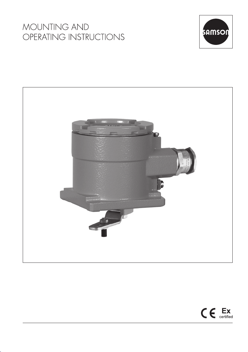
3.1 Device overview and operating controls........................................................3-1
3.2 Technical data ............................................................................................3-2
3.3 Dimensions in mm.......................................................................................3-5
4 Shipment and on-site transport ...................................................................4-1
4.1 Accepting the delivered goods .....................................................................4-1
4.2 Removing the packaging from the position transmitter....................................4-1
4.3 Transporting the position transmitter .............................................................4-1
4.4 Storing the position transmitter.....................................................................4-1
5 Installation.................................................................................................5-1
5.1 Installation conditions..................................................................................5-1
5.2 Preparation for installation...........................................................................5-2
5.2.1 Lever and pin position .................................................................................5-2
5.3 DirectattachmenttoType3277andType3277-5Actuators...........................5-4
5.4 AttachmentaccordingtoIEC60534-6(NAMURrib) .....................................5-6
5.5 AttachmenttoType3510Micro-owValve ...................................................5-8
5.6 AttachmenttorotaryactuatorsaccordingtoVDI/VDE3845 ........................5-10
5.6.1 Lightversion .............................................................................................5-10
5.6.2 Heavy-dutyversion ...................................................................................5-12
5.7 Establishingelectricalconnections ..............................................................5-14
5.8 Mounting accessories ................................................................................5-17
6 Operation..................................................................................................6-1
6.1 Operatorkeysandmenustructure................................................................6-1
6.2 Lockingtheconguration.............................................................................6-3
7 Start-up .....................................................................................................7-1
7.1 Determiningthemountingsituation ..............................................................7-2
7.2 Determiningthepositionat4mA.................................................................7-2
7.2.1 Determiningthepositionat20mA...............................................................7-3
7.2.2 Issuingatestcurrent....................................................................................7-4

Contents
EB 4749 EN
8 Operation..................................................................................................8-1
8.1 Resetting the position transmitter to default settings ........................................8-2
9 Malfunctions ..............................................................................................9-1
9.1 Troubleshooting ..........................................................................................9-1
9.2 Emergency action .......................................................................................9-1
10 Servicing..................................................................................................10-1
10.1 Periodic inspection and testing of the position transmitter .............................10-2
11 Decommissioning .....................................................................................11-1
12 Removal ..................................................................................................12-1
13 Repairs ....................................................................................................13-1
13.1 Servicing explosion-protected devices.........................................................13-1
13.2 Returning devices to SAMSON ..................................................................13-2
14 Disposal...................................................................................................14-1
15 Certicates ..............................................................................................15-1
16 Annex......................................................................................................16-1
16.1 After-salesservice.....................................................................................16-1

EB 4749 EN 1-1
Safety instructions and measures
1 Safety instructions and measures
Intended use
TheSAMSONType4749PositionTransmitterismountedontocontrolvalvesandconverts
thelinearorrotarymotionofacontrolvalveintoa4to20mAstandardizedsignal.Thede-
viceisdesignedtooperateunderexactlydenedconditions(e.g.temperature).Therefore,
operators must ensure that the position transmitter is only used in applications where the op-
erating conditions correspond to the technical data. In case operators intend to use the posi-
tiontransmitterinotherapplicationsorconditionsthanspecied,contactSAMSON.
SAMSON does not assume any liability for damage resulting from the failure to use the
device for its intended purpose or for damage caused by external forces or any other
external factors.
ÎRefertothetechnicaldataforlimitsandeldsofapplicationaswellaspossibleuses.
Reasonably foreseeable misuse
TheType4749PositionTransmitterisnot suitable for the following applications:
−Useoutsidethelimitsdenedduringsizingandbythetechnicaldata
Furthermore, the following activities do not comply with the intended use:
−Useofnon-originalspareparts
−Performing maintenance activities not described in these instructions
Qualications of operating personnel
The position transmitter must be mounted, started up and serviced by fully trained and
qualiedpersonnelonly;theacceptedindustrycodesandpracticesmustbeobserved.
According to these mounting and operating instructions, trained personnel refers to
individualswhoareabletojudgetheworktheyareassignedtoandrecognizepossible
hazardsduetotheirspecializedtraining,theirknowledgeandexperienceaswellastheir
knowledge of the applicable standards.
Explosion-protected versions of this device must be operated only by personnel who has
undergonespecialtrainingorinstructionsorwhoisauthorizedtoworkonexplosion-
protecteddevicesinhazardousareas.

1-2 EB 4749 EN
Safety instructions and measures
Personal protective equipment
No personal protective equipment is required for the direct handling of the position transmit-
ter. Work on the control valve may be necessary when mounting or removing the device.
ÎObservetherequirementsforpersonalprotectiveequipmentspeciedinthevalvedocu-
mentation.
ÎCheck with the plant operator for details on further protective equipment.
Revisions and other modications
Revisions,conversionsorothermodicationsoftheproductarenotauthorizedbySAMSON.
Theyareperformedattheuser'sownriskandmayleadtosafetyhazards,forexample.
Furthermore, the product may no longer meet the requirements for its intended use.
Warning against residual hazards
To avoid personal injury or property damage, plant operators and operating personnel must
preventhazardsthatcouldbecausedinthecontrolvalvebytheprocessmedium,theoperat-
ing pressure, the signal pressure or by moving parts by taking appropriate precautions. Plant
operatorsandoperatingpersonnelmustobserveallhazardstatements,warningandcaution
notes in these mounting and operating instructions, especially for installation, start-up and
service work.
If inadmissible motions or forces are produced in the pneumatic actuator as a result of the
supply pressure, it must be restricted using a suitable supply pressure reducing station.
Responsibilities of the operator
The operator is responsible for proper operation and compliance with the safety regulations.
Operators are obliged to provide these mounting and operating instructions to the operating
personnel and to instruct them in proper operation. Furthermore, the operator must ensure
that operating personnel or third parties are not exposed to any danger.
Responsibilities of operating personnel
Operating personnel must read and understand these mounting and operating instructions as
wellasthespeciedhazardstatements,warningandcautionnotes.Furthermore,theoperat-
ing personnel must be familiar with the applicable health, safety and accident prevention
regulations and comply with them.
Referenced standards and regulations
DeviceswithaCEmarkingfullltherequirementsoftheDirectivesRoHS2011/65/EUas
wellas2014/30/EUand,dependingontheversion,2014/34/EUforexplosion-protected
applications.ThisEUdeclarationofconformityisincludedintheannexofthisdocument.

EB 4749 EN 1-3
Safety instructions and measures
Referenced documentation
The following documents apply in addition to these mounting and operating instructions:
−The mounting and operating instructions of the components on which the position trans-
mitter is mounted (valve, actuator, valve accessories etc.).
1.1 Notes on possible severe personal injury
DANGER
!
Risk of fatal injury due to the ignition of an explosive atmosphere.
Incorrect installation, operation or maintenance of the position transmitter in potentially
explosive atmospheres may lead to ignition of the atmosphere and ultimately to death,
even with a harmless supply voltage.
ÎFormountingandelectricalinstallationinhazardousareas,observetheexplosion
protection approvals as well as the relevant electrotechnical regulations and the
accidentpreventionregulationsthatapplyinthecountryofuse.EN60079-14
applies in Europe.
ÎDo not connect the electrical supply before mounting is completed.
ÎInstallation, operation or maintenance of the position transmitter must only be
performedbypersonnelwithqualicationsaccordingtoClause4.5ofIEC60079-14
whohasundergonespecialtrainingorinstructionsorwhoisauthorizedtoworkon
explosion-protecteddevicesinhazardousareas.
Risk of fatal injury as a result of electrostatic discharge at the device.
An electric spark generated by electrostatic discharge may lead to ignition of a potential-
ly explosive atmosphere and cause death.
ÎInhazardousareas,mountthedeviceinsuchawaythatelectrostaticchargingcannot
take place.
Loss of the explosion protection due to damage to the cover's thread and/or the
connecting thread.
ÎDonotopendeviceswithameproofenclosureswhiletheyareenergized.

1-4 EB 4749 EN
Safety instructions and measures
1.2 Notes on possible personal injury
WARNING
!
Crush hazard arising from moving parts on the valve and actuator.
Control valves contain moving parts (actuator and plug stem), which can injure hands or
ngersifinsertedintothevalve.
ÎDo not touch any moving valve parts while the control valve is in operation.
ÎBefore performing any mounting or installation work on the position transmitter, put the
control valve out of operation by disconnecting and locking the supply and control
signal.
Incorrect electrical connection will render the explosion protection unsafe.
ÎAdhere to the terminal assignment.
ÎDo not undo the enameled screws.
ÎDonotexceedthemaximumpermissiblevaluesspeciedintheECtypeexamination
certicateswheninterconnectingintrinsicallysafeelectricalequipment(UiorU0, lior I0,
Pior P0, Cior C0and Lior L0).
The use of unapproved cable glands will render the explosion protection unsafe.
ÎFordeviceswithameproofenclosure,onlyusecableglandsandscrewplugswhich
areapprovedfortypeofprotectionExdandthecertiedtemperaturerange.
Opening the position transmitter in potentially explosive dust atmospheres will render
the explosion protection unsafe.
ÎDo not open the enclosure cover of the position transmitter in potentially explosive dust
atmospheres.

EB 4749 EN 1-5
Safety instructions and measures
1.3 Notes on possible property damage
NOTICE
!
Risk of malfunction due to incorrect mounting parts/accessories or incorrect assignment
of lever and pin position.
ÎOnlyusemountingparts/accessorieslistedinthesemountingandoperatinginstruc-
tions to mount the position transmitter.
ÎObserve the type of attachment.
ÎObserve the assignment between lever and pin position.
Risk of malfunction due to calibration not being performed.
Thezeroandspancalibrationallowthepositiontransmittertobeadaptedtothemounting
situation.Thepositiontransmitterisonlyreadyforoperationafterthezeroandspanhave
been calibrated.
ÎPerform calibration before initial start-up.
ÎCalibrate the position transmitter after changing the mounting position.
Risk of position transmitter damage due to incorrect grounding of the electric welding
equipment.
ÎDo not ground electric welding equipment near to the position transmitter.

1-6 EB 4749 EN

EB 4749 EN 2-1
Markings on the device
2 Markings on the device
2.1 Nameplate
See technical data for ambient temperature
Analog position transmitterAnalog position transmitter
SAMSON AG D-60314 Frankfurt
0044
Made in Germany
Model 4749-
3
Firmware
1
Hardware
2
6
Var.-ID 4Serial no. 5
SAMSON AG D-60314 Frankfurt Made in Germany
Model 4749-
3
Firmware
1
Hardware
2
Var.-ID 4
Serial no. 5
7
4749 4749
WARNING-POTENTIAL ELECTROSTATIC CHARGING HAZARD*
* See EU Type Examination Certificate for further values
1) Thersttwoguresoftheserialnumberinreverseorderindicatetheyearof
manufacture(example:serialnumber71xxxxxÎYear of manufacture =
2017).
1 Firmware version
2Hardwareversion
3 Model number
4CongurationID
5 Serial number1)
6Type of protection code
6a Checkbox for type of protection
Exi
6b TypeofprotectionExi
6c Checkbox for type of protection
Exd
6d TypeofprotectionExd
7Temperature limits in the test
certicatesfortheexplosion-
protected devices
Explosion-protected version Version without explosion protection
Analog position transmitter
SAMSON AG D-60314 Frankfurt
0044
Made in Germany
Model 4749-
3
Firmware
1
Hardware
2
6b
6d
Var.-ID 4Serial no. 5
7
4749
WARNING-POTENTIAL ELECTROSTATIC CHARGING HAZARD*
* See EU Type Examination Certificate for further values
6a
6c
Types4749-11xand4749-21x
Type4749-18x
All types
Type of protection code for Type4749-18x
ÎBefore mounting the position transmitter, check the box for the type of protection required
fortheambientconditionsonthenameplate(checkbox6afortypeofprotectionExior
checkbox6cfortypeofprotectionExd).

2-2 EB 4749 EN
Markings on the device
2.2 Article code
Position transmitter Type4749- x x x x x x x x x 0 0 xxxx
Version
Analog position transmitter 0
Explosion protection
Without 0 0 0
ATEX II2GExiaIICT6...T4Gb/
II 2 D Ex ia IIIC T85 °C Db 110
IECEx ExiaIICT6...T4Gb/
Ex ia IIIC T85 °C Db 111
ATEX
II2GExiaIICT6...T4GB
II 2 D Ex ia IIIC T85 °C DB
or
II2GExdbIICT6…T4Gb
II 2 D Ex tb IIIC T80 °C Db
180
IECEx
ExiaIICT6…T4Gb
Ex ia IIIC T85 °C Db
or
ExdbIICT6…T4Gb
ExtbIIICT80°CDb
181
ATEX II2GExdbIICT6...T4Gb/
II2DExtbIIICT80°CDb 210
IECEx ExdbIICT6...T4Gb/
ExtbIIICT80°CDb 211
Electrical threaded connection
M20x1.5 0
½NPT 1
Enclosure material
Aluminum (standard) 0
Special applications
Without 0
Additionalcertication
Without 0
Temperature range
Standard 0

EB 4749 EN 2-3
Markings on the device
Position transmitter Type4749- x x x x x x x x x 0 0 xxxx
Hardwareversion
1.00.00 9 9
Firmware version
1.00.02 9 8

2-4 EB 4749 EN

EB 4749 EN 3-1
Design and principle of operation
3 Design and principle of oper-
ation
TheType4749PositionTransmitterconverts
the linear or rotary motion of a control valve
intoanelectric4to20mAstandardized
signal.
The angle of the position transmitter's axis is
measured by the magnetoresistive measuring
system and converted into an electric signal.
Two pushbuttons are used to operate the
device and make device settings. Two LEDs
(red and green) indicate the menu items and
settings.
To operate the position transmitter, a
transmittersupplyvoltageofUB=12to36V
isrequiredforthe4to20mAmeasuring
circuit.
3.1 Device overview and operating controls
3
2
1
–
+–
9
10
6 7
4
8
5
1 Enclosure cover
2 Stop screw
3 Grounding connection (external)
4key
5key
6Red LED
7Green LED
8 Terminal
9 Grounding connection (internal)
10 Shaft locking
Fig.3-1: Operating controls

3-2 EB 4749 EN
Design and principle of operation
3.2 Technical data
Type4749 Position Transmitter
Measuring range
Measurement method Magnetoresistive measuring system
Measured travel for DirectattachmenttoType3277: 3.6to30mm
AttachmentaccordingtoIEC60534-6(NAMUR): 5to300mm
AttachmentaccordingtoVDI/VDE3847: 5to300mm
Attachment to rotary actuators: 24 to 100°
Power supply
Input voltage 12to36VDC
Output 4to20mA·Two-wiredevice,reversepolarityprotection
Residual current ≤3.6mA
Permissible load RBinΩ RB=(UB–12V)/0.020A
Static destruction limit 38VDC,30VAC
Power consumption <0.2W
Measuring accuracy
Reference conditions CalibratedwithU=24VDC,TU=20°C
Zero error <0.1%accordingtoDINEN60770
Hysteresis ≤0.1%accordingtoDINEN60770
Nonlinearity <0.3%accordingtoDINEN60770
Effect of supply voltage on
zeroandspan
<0.05%accordingtoDINEN60770
Effect of ambient tempera-
tureonzeroandspan
<0.1%/10KaccordingtoDINEN60770
Long-term stability <0.1%accordingtoDINEN60770
Start-up time 1200ms
Output rate 1ms

EB 4749 EN 3-3
Design and principle of operation
Environmental conditions and permissible temperatures
PermissibleenvironmentalconditionsaccordingtoEN60721-3
Storage 1K6(relativehumidity≤95%)
Transport 2K4
Operation 4K2or4K3(dependingonthetemperaturerange)
–20to+85°C: All versions
–40to+85°C: With metal cable glands
Observethelimitsinthetestcerticateforexplosion-protectedversions.
Resistance to vibration
Vibrations(sinusoidal) AccordingtoDINEN60068-2-6:
2to9Hz;3.5mmamplitude
10to200Hz;10m/s²acceleration
200to500Hz;15m/s²acceleration
Noise AccordingtoDINEN60068-2-64:
10to200Hz;amplitude1(m/s²)²/Hz
200to2000Hz;amplitude0.3(m/s²)²/Hz
Requirements
EMC ComplyingwithEN61000-6-1,EN61000-6-2,EN61000-6-3,
EN61000-6-4,EN61000-6-7,EN61326andNAMURRecommen-
dationNE21
Degree of protection IP66
Conformity
Electrical connections
Cable glands M20x1.5or½NPT
Terminals Screwterminalsfor0.2to2.5mm²wirecross-section
Explosion protection
ATEX, IECEx See‘Summaryofexplosionprotectionapprovals’onpage3-4.
Materials
Enclosure and cover Die-castaluminumENAC-44300/ENAC-43000accordingto
DINEN1706,chromatedandpowderpaintcoated
Cable glands Polyamide, nickel-plated brass
Other external parts Stainlesssteel1.4301/1.4310+1.4404/1.4409(316L)
Weight 0.7kg

3-4 EB 4749 EN
Design and principle of operation
Summary of explosion protection approvals
Type Certication Type of protection
4749-110 EC type examina-
tioncerticate
Number KIWA18ATEX0031X II2GExiaIICT6...T4Gb/
II2DExiaIIICT85°CDb
Date 2019-01-09
4749-111 IECEx Number IECExKIWA18.0014X ExiaIICT6...T4Gb/
ExiaIIICT85°CDb
Date 2019-01-09
4749-180 EC type examina-
tioncerticate
Number KIWA19ATEX0038X II2GExiaIICT6…T4Gb
II 2 D Ex ia IIIC T85 °C Db
or
II2GExdbIICT6…T4Gb
II 2 D Ex tb IIIC T80 °C Db
Date 2019-10-10
4749-181 IECEx
Number IECExKIWA19.0022X ExiaIICT6…T4Gb
ExiaIIICT85°CDb
or
ExdbIICT6…T4Gb
ExtbIIICT80°CDb
Date 2019-10-10
4749-210 EC type examina-
tioncerticate
Number KIWA18ATEX0036X II2GExdbIICT6...T4Gb/
II2DExtbIIICT80°CDb
Date 2018-11-11
4749-211 IECEx Number IECExKIWA18.0017X ExdbIICT6...T4Gb/
ExtbIIICT80°CDb
Date 2018-11-11

EB 4749 EN 3-5
Design and principle of operation
3.3 Dimensions in mm
94
77
40
99
80
30

3-6 EB 4749 EN
Other manuals for 4749
1
Table of contents
Other Samson Transmitter manuals