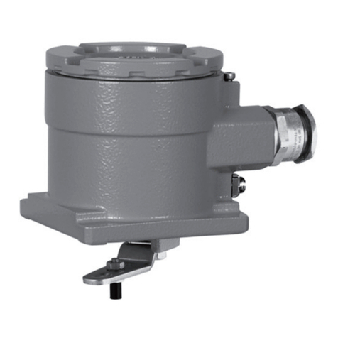
Samson 4749 User manual

Type4749 PositionTransmitter
This quick guide does not replace the mounting and operating inst-
ructions supplied with the device. Observe the safety instructions as
well as the warning and caution notes specied in the mounting and
operating instructions.
1 Mounting
Directattachment to SAMSON Type3277 Actuator
Travel [mm] Actuator [cm²] Lever Pin position
7.5 120 M25
15 120, 175, 240, 350 M35
30 355, 700, 750 M50
ÎTo mount the position transmitter, lift the lever so that the follower
pin rests on the follower clamp of the actuator stem. Make sure
the lever can move freely.
NAMURattachment
Travel [mm] Actuator [cm²] Lever Pin position
7.5 120 (withe Type 3510 Valve) S17
7.5 120 M25
15 120, 175, 240, 350 M35
7.5 700, 750 M35
15 and 30 355, 700, 750 M50
30 1000, 1400, 2800 L70
60 1000, 1400, 2800 L100
120 1400, 2800 XL 200
ÎDetermine the travel range of the control valve (CLOSED position
to as far it will go in the other direction) by applying the max.
supply air to the actuator and then venting the actuator comple-
tely.
ÎFasten the lever with the follower pin onto the shaft of the position
transmitter.
Î
Fasten the NAMUR bracket onto the valve yoke so that it is aligned
centrally to the slot of the follower plate when the travel position
is at approx. 50%.
Î
Fasten the position transmitter to the NAMUR bracket, making
sure that the follower pin is in the slot of the follower plate. Make
sure the lever can move freely.
Attachmenttorotaryactuators
Lever Pin position
M90°
ÎPlace the valve in the CLOSED position.
ÎPlace the follower plate on the slotted actuator shaft and fasten it
to the coupling wheel. Mount the top and bottom brackets to the
actuator.
ÎFasten the position transmitter on the bracket. Make sure that:
–
The lever with its follower pin engages into the slot of the
coupling wheel (taking the opening direction into account).
– The lever in the mid valve position is parallel to the long side
of the position transmitter housing.
Stellungsmelder Typ4749
Die vorliegende Kurzanleitung ersetzt nicht die dem Gerät beiliegen
-
de Einbau- und Bedienungsanleitung. Die in der Einbau- und Bedie-
nungsanleitung enthaltenen Sicherheits- und Warnhinweise sind zu
beachten.
1 Montage
Direktanbau an SAMSON-Antrieb Typ3277
Hub [mm] Antrieb [cm²] Hebel Stiftposition
7, 5 120 M25
15 120, 175, 240, 350 M35
30 355, 700, 750 M50
Î
Zur Montage des Stellungsmelders den Hebel anheben, damit der
Abtaststift auf dem Mitnehmer der Antriebsstange zum Liegen
kommt. Auf freie Hebelbeweglichkeit achten.
NAMUR-Anbau
Hub [mm] Antrieb [cm²] Hebel Stiftposition
7, 5 120 (mit Ventil Typ3510) S17
7, 5 120 M25
15 120, 175, 240, 350 M35
7, 5 700, 750 M35
15 und 30 355, 700, 750 M50
30 1000, 1400, 2800 L70
60 1000, 1400, 2800 L100
120 1400, 2800 XL 200
Î
Hubbereich des Stellventils (Stellung ZU bis zum gegenüberlie-
genden Anschlag) durch volles Be- und Entlüften ermitteln.
ÎEntsprechenden Hebel mit Abtaststift auf der Welle des Stellungs-
melders verschrauben.
ÎNAMUR-Winkel so am Ventiljoch festschrauben, dass er bei ca.
50% Hubstellung mittig zum Schlitz der Mitnehmerplatte steht.
Î
Stellungsmelder am NAMUR-Winkel befestigen. Der Abtaststift
muss im Schlitz der Mitnehmerplatte liegen. Auf freie Hebelbe-
weglichkeit achten.
AnbauanSchwenkantriebe
Hebel Stiftposition
M90°
ÎVentil in ZU-Stellung bringen.
ÎMitnehmer auf die geschlitzte Antriebswelle aufstecken und zu-
sammen mit Kupplungsrad verschrauben. Untere und obere Be-
festigungswinkel am Antrieb montieren.
ÎStellungsmelder am Winkel festschrauben. Darauf achten, dass
–
der Hebel mit seinem Abtaststift unter Berücksichtigung der
Öffnungsrichtung in den Schlitz des Kupplungsrads eingreift.
– der Hebel in der mittleren Hubstellung parallel zur Längsseite
des Stellungsmeldergehäuses steht.
!
българскиезик[BG] · Čeština[CS] · Dansk[DA] · Deutsch[DE] · ελληνικά[EL]
English[EN] · Español[ES] · Eesti[ET] · Suomi[FI] · Français[FR]
Hrvatskijezik[HR] · Magyar[HU] · Italiano[IT] · 日本語 [JA]
Lietuviųkalba[LT] · Nederlands[NL] · Polski[PL] · Português[PT]
Română [RO] · Русский[RU] · Slovenčina[SK] · Slovenščina[SL] ·
Svenska[SV] · Türkçe[TR] · 中文[ZH]
Îwww.samsongroup.com

Edition July 2020 QuickGuideKA4749EN
3 Operation
Press key to open the menu level. Press key once to jump to the
next item within the level. Press key to activate an item. Press
key to select a function within this item. By pressing key, save or
execute the selected function.
To exit without saving or executing a function, press and hold key
and press key.
4 Troubleshooting
The LEDs illuminate constantly or blink to indicate a malfunction. What
the indicated malfunctions mean and their possible causes as well as
the recommended action are listed in the table below:
See associated mounting and operating instructions for details:
uEB4749 for Type4749 Position Transmitter
Itemno.,menuitem/function LED Blinkingpattern
0Normalstate Green Illuminated constantly
1Enableconguration Green ... ...
Enable conguration Red 2x ... 2x ... 2x
Lock conguration Red ... ...
2Mounting Green 2x ...2x ...2x
Linear actuator Red ... ...
Rotary actuator Red 2x ... 2x ... 2x
3Positionat4mA Green 3x ... 3x ... 3x
Save position Red ... ...
4Positionat20mA Green 4x ... 4x ... 4x
Save position Red ... ...
5Issueatestcurrent Green 5x ... 5x ... 5x
4mA output Red ... ...
20mA output Red 2x ... 2x ... 2x
6Resettodefaultsettings Green 6x ... 6x ... 6x
Execute reset Red ... ...
Indicator GreenLEDblinks
Meaning Maintenance demanded/internal error
Action Replace device. Contact SAMSON's After-sales
Service.
Indicator RedLEDblinks
Meaning Out of specication
Action Check mounting, control valve, power supply and
conguration.
Indicator RedLEDilluminated
Meaning Failure/internal error
Action Press key to reset.
Contact SAMSON's After-sales Service.
2 Preparationforstart-up
ÎConnect supply voltage (12 to 36VDC).
Ausgabe Juli 2020 KurzanleitungKA4749
3 Bedienung
Mit der -Taste die Menüebene aufrufen. Betätigen der -Taste er-
höht die Nummer innerhalb der Ebene. Innerhalb der Menüebene
mit der -Taste die Auswahlebene aufrufen. Mit der -Taste wird in
der Auswahlebene der Auswahlpunkt gewählt. Ein angewählter Punkt
in der Auswahlebene wird durch Drücken der -Taste gespeichert
bzw. die angewählte Funktion ausgeführt.
Die Auswahlebene kann jederzeit ohne Speichern oder Ausführen
einer Funktion verlassen werden. Dazu die -Taste gedrückt halten
und dann die -Taste drücken.
4 Störungen
Eine Störung wird durch konstantes Leuchten oder Blinken der LEDs
angezeigt. Die Bedeutung der angezeigten Fehler sowie mögliche
Ursachen und Maßnahmen zur Abhilfe zeigt folgende Tabelle:
Einzelheiten vgl. zugehörige Einbau- und Bedienungsanleitung:
uEB4749 für Stellungsmelder Typ4749.
Ebene,Menü-/Auswahlpunkt LED Blinkmuster
0Normalanzeige grün leuchtet konstant
1Kongurationsfreigabe grün ... ...
Konguration freigeben rot 2x ...2x ...2x
Konguration sperren rot ... ...
2Anbau grün 2x ... 2x ... 2x
Hubantrieb rot ... ...
Schwenkantrieb rot 2x ...2x ...2x
3Stellungbei4mA grün 3x ... 3x ... 3x
Stellung speichern rot ... ...
4Stellungbei20mA grün 4x ... 4x ... 4x
Stellung speichern rot ... ...
5Teststromausgeben grün 5x ... 5x ... 5x
Ausgabe 4mA rot ... ...
Ausgabe 20mA rot 2x ...2x ...2x
6Rücksetzen(Werkseinstellung) grün 6x ... 6x ... 6x
Rücksetzen ausführen rot ... ...
Anzeige grüneLEDblinkt
Bedeutung Wartungsanforderung/interner Fehler
Maßnahme Gerät austauschen,
After Sales Service von SAMSON kontaktieren.
Anzeige roteLEDblinkt
Bedeutung außerhalb der Spezikation
Maßnahme Anbau, Stellventil, Stromversorgung und Kongurati-
on überprüfen.
Anzeige roteLEDleuchtet
Bedeutung Ausfall/interner Fehler
Maßnahme Fehler durch Drücken der -Taste zurücksetzen.
After Sales Service von SAMSON kontaktieren.
2 Inbetriebnahmevorbereiten
ÎVersorgungsspannung (12 bis 36VDC) anschließen.
Other manuals for 4749
1
Other Samson Transmitter manuals
Popular Transmitter manuals by other brands

Daniels
Daniels VT-3H040 instruction manual

Audiovox
Audiovox APS 95 BT3S Programming guide

Dwyer Instruments
Dwyer Instruments CDTV Series Specifications-installation and operating instructions

Greystone Energy Systems
Greystone Energy Systems TE500AD Series installation instructions

Vega
Vega VEGABAR 82 Quick setup guide

RKI Instruments
RKI Instruments 65-2336RK Operator's manual

Nuomm
Nuomm NEWSCASTER VT2 user manual

Emerson
Emerson Rosemount 3408 Reference manual

ACR Electronics
ACR Electronics COBHAM B406-4 Abbreviated component maintenance manual

M-system
M-system W2PA instruction manual

August
August CR100 user manual

Endress+Hauser
Endress+Hauser Liquiline M OM42 technical information