manuals.online logo
Brands
  1. Home
  2. •
  3. Brands
  4. •
  5. Samsung
  6. •
  7. Air Conditioner
  8. •
  9. Samsung AS30C2BC User manual

Samsung AS30C2BC User manual

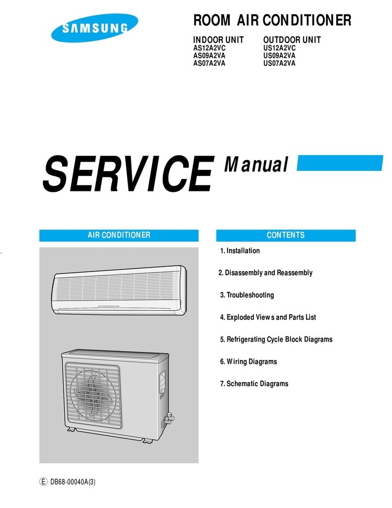
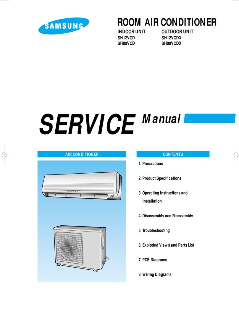
SERVICE Manual
CONTENTSAIR CONDITIONER
1. Installation
2. Disassembly and Reassembly
3. Troubleshooting
4. Exploded Views and Parts List
5. Refrigerating Cycle Block Diagrams
6. PCB Diagrams
7. Wiring Diagrams
8. Schematic Diagrams
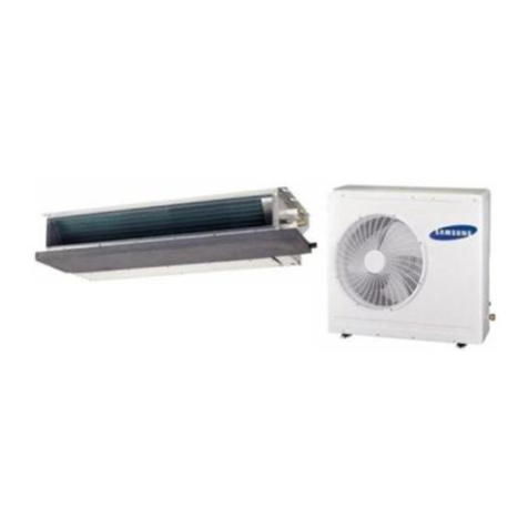
ROOM AIR CONDITIONER
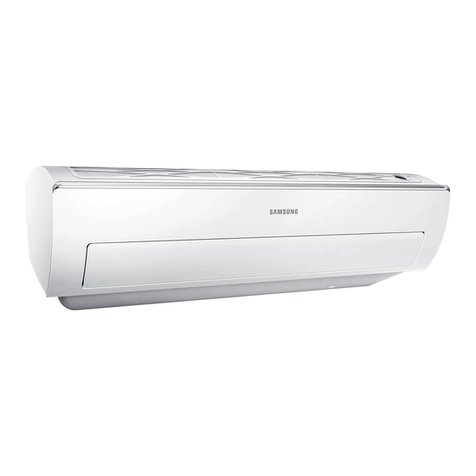
INDOOR UNIT
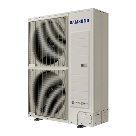
AS30C2BC OUTDOOR UNIT
US30C2BC
E DB98-05388A(1)
DB98-05388A(1)-CO 3/11/02 10:55 AM Page 1
1
1. Installation
1-1 Refrigerant Refill Procedure
• Refill an air-conditioner with refrigerant when refrigerant has been leaked at installing or using
1. Purge air(for new installation only).
3. Connect the tank to refill with Refrigerant
4. Set the unit to cool operation mode.
7. Stop operation of the air conditioner.
9. Close the cap of each valve.
2. Turn the 3-way valve clockwise to close, connect the
pressure gauge(low pressure side) to the service valve,
and open the 3-way valve again.
5. Check the pressure indicated by the pressure
gauge(low pressure side).
* Standard pressure is should be 4.5~5.5kg/cm2in a
regular, high operation mode.
6. Open the refrigerant tank and fill with refrigerant until
the rated pressure is reached.
* It is recommended not to pour the refrigerant in too
quickly, but gradually while operating a pressure valve.
8. Close the 3-way valve, disconnect the pressure gauge,
and open the 3-way valve again.
R-22
Suspension hook
High
pressure
gauge
Hand
wheel
Finger tight
fittings
Connected to
high pressure
side
Charging
line
For mounting
other and of
hose when
not in use
Compound
gauge
DB98-05388A(1)-1 3/11/02 12:52 PM Page 1
2
1-2 “Pump down” Procedure
Relocation of the air conditioner
• Refer to this procedure when the unit is
relocated.
1. Carry out the pump down procedure (refer
to the details of 'pump down').
2. Remove the power cord.
3. Disconnect the assembly cable from the
indoor and outdoor units.
4. Remove the flare nut connecting the indoor
unit and the pipe.
At this time, cover the pipe of the indoor
unit and the other pipe using a cap or
vinyl plug to avoid foreign material enter-
ing.
Relocation of the air conditioner
5. Disconnect the pipe connected to the
outdoor unit.
At this time, cover the valve of the outdoor
unit and the other pipe using a cap or
vinyl plug to avoid foreign material
entering.
6. Make sure you do not bend the connection
pipes in the middle and store together with
the cables.
7. Move the indoor and outdoor units to a
new locatioon.
8. Remove the mounting plate for the indoor
unit and move it to a new location.
Pump down shall be carried out when an evaporator is replaced or when the unit is relocated in
another area.
1. Remove the caps from the 2-way valve and the 3-way valve.
3. Set the unit to cool operation mode.
(Check if the compressor is operating.)
5. When the pressure gauge indicates "0" turn the 3-way valve
clockwise to close.
4. Turn the 2-way valve clockwise to close.
6. Stop operation of the air conditioner.
7. Close the cap of each valve.
2. Turn the 3-way valve clockwise to close and connect
a pressure gauge(low pressure side) to the service valve,
and open the 3-way valve again.
2-Way Valve
3-Way Valve
DB98-05388A(1)-1 3/11/02 12:52 PM Page 2
3
2. Disassembly and Reassembly
2-1 Indoor Unit
Stop operation of the air conditioner and remove the power cord before repairing the unit.
No Parts Procedure Remark
Front Grille
!1) Stop the air conditioner operation and block the
main power.
2) Seperate tape of front panel upper.
3) Contract the second finger to the left, and right
handle and pull to open the inlet grille.
4) Take the left and right filter out.
5) Loosen one of the right fixing screw and seper-
ate the terminal cover.
6) Loosen four fixing screws of front grille.
7) Pull the upper four parts of discharge softly for
the outside cover to be pulled out.
8) Pull softly the lower part of discharge and push
it up.
Caution;
Fix the hook of four parts and assembly the front
panel.
* Take the Deodorizing and Electrostatic filter
out. (Optional)
DB98-05388A(1)-1 3/11/02 12:52 PM Page 3
4
No Parts Procedure Remark
Ass’y Tray Drain.
Electrical Parts
(Main PCB)
Heat Exchanger
@
#
$
1) Do “1”, above.
Separate the drain hose from the extension
drain hose.
2) Take the display PCB out.
(Right of indoor unit)
3) Pull tray drain out from the back body.
1) Do “1”, “2”, above.
2) Take all the connector of PCB upper side out.
(Inclusion Earth Wire)
3) Separate the outdoor unit connection wire from
the terminal block.
4) If pulling the Main PCB up. it will be taken out.
1) Do “1” and “2”, “3”, above.
2) Loosen one fixing screw of right side.
3) Separate the holder-back body at the upper side
and holder at the rearside.
4) Loosen the one fixing screw of left side.
5) Lifting the heat exchanger up a little to push the
up side for separation from the indoor unit.
DB98-05388A(1)-1 3/11/02 12:52 PM Page 4
5
No Parts Procedure Remark
Fan Motor
and
Cross Fan
%1) Do “1” “2” ”3” “4”, above.
2) Loosen the fixing five screws and separate the
holder motor.
3) Loosen the fixing screw of fan motor.
4) Separate the fan motor from the right fan.(A)
5) Loosen the fixing screw of the left fan.(B)
6) Seperate the both fan from the back body.
A
B
DB98-05388A(1)-1 3/11/02 12:52 PM Page 5
6
2-2 Outdoor Unit
Parts Procedure Remark
COVER TOP
BACK CABI
CONTROL BOX
COVER FRONT
1) Loosen the screws on the cover top,
and remove the cover top.
1) Loosen the screws on the side cabinet,
and remove the side cabinet.
1) Loosen the screw on the control box,
and remove the control box.
2) Separate the wiring of control box.
1) Loosen the screws on the cover front,
and remove the cover front.
DB98-05388A(1)-1 3/11/02 12:52 PM Page 6
7
3. Troubleshooting
3-1 Items to be checked first
1) The input voltage should be rating voltage 10% range.
The airconditioner may not operate properly if the voltage is out of this range.
2) Is the link cable linking the indoor unit and the outdoor unit linked properly?
The indoor unit and the outdoor unit shall be linked by 6 cables.
Check the terminals if the indoor unit and outdoor unit are properly linked by the same number of
cables.
Otherwise the airconditioner may not operate properly.
3) When a problem occurs due to the contents illustrated in the table below it is a symptom not related to
the malfunction of the airconditioner.
4) Indoor unit observes operation condition of the air conditioner, and displays self diagnosis details on the
display panel.
NO Operation of air conditioner
1 The STD operation indication LED blinks when a
power plug of the indoor unit is plugged in for the first time.
2 In a COOL operation mode, the compressor does not
operate at a room temperature higher than the setting
temperature that the INDOOR FAN should operate.
3 Fan speed setting is not allowed in AUTO or DRY mode.
4 Compressor stops operation intermittently in DRY mode.
5 The compressor stops intermittently in a COOL mode or DRY
mode, and fan speed of the indoor unit decreases.
It indicates power is on. The LED stops blinking if the operation
ON/OFF button on the remote control unit is pushed.
In happens after a delay of 3 minutes when the compressor is
reoperated. The same phenomenon occurs when a power is on.
As a phenomenon that the compressor is reoperated after a delay of
3 minutes, the indoor fan is adjusted automatically with reference
to a temperature of the air blew
The speed of the indoor fan is set to LL in DRY mode.
Fan speed is 5 steps is selected automatically in AUTO mode.
Compressor operation is controlled automatically in DRY mode
depending on the room temperature and humidity.
The compressor stops intermittently or the fan speed of the indoor
unitdecreasestopreventinside/outsideairfrozendependingonthe
inside/outside air temperature.
Explanation
NO Display
1 STD LED blinking (1Hz)
2 TIMER LED blinking (1Hz)
3 STD and TIMER LED blinking (1Hz)
4 BIO LED blinking (1Hz)
5 STD, BIO and TIMER LED blinking(1Hz)
6 All LED blinking(1Hz)
Restore from power failure (input initial power)
Indoor unit Room sensor Error (open or short)
Indoor unit heat exchanger temperature sensor Error (open or short)
Indoor fan malfunctioning (for spead is Below 450rpm)
EEPROM Error
Option Erro (option wasn’t setup or option data error)
Self Diagnosis
DB98-05388A(1)-1 3/11/02 12:52 PM Page 7
8
3-2 Fault Diagnosis by Symptom
3-2-1 No Power(completely dead)-Initial diagnosis
1) Checklist :
(1) Is input voltage normal? The rating voltage ±10% range.
(2) Is AC power linked correctly?
(3) Is input voltage of DC regulator IC KA7805 (IC02) normal? (11.5VDC-12.5VDC)
(4) Is output voltage of DC regulator IC KA7805 (IC02) normal? (4.5VDC-5.5VDC)
2) Troubleshooting procedure
Replace PCB
display
Is DC voltage of PCB
display normal?
Remove power cord and plug in again
in approx. 5 seconds
Is operation lamp blinking?
Does operation start when
run/stop button on the remote
controller unit pushed?
Is transmission display of the remote
controller unit blinking?
Is "beep"sound heard from the main
unit?
Is DC voltage of the PCB module
normal?
Are voltages of #40 (compressor), and#41 or
#42(outdoor fan) of the micom normal? ; 5VDC
Is voltage of #39 (indoor fan) of the micom
normal?
Is voltage at #17 terminal of the Micom normal?
;
0VDC
Is voltage at #16 terminal of the Micom normal?
;
5VDC
Is the rating Voltage ±10%
range applied to the
between #1 and #3 of CN78
•Check linkage between
power cord and
terminal tap
•Check fuse
Is 11.5~12.5VDC appear in
the input side of the DC
regulator IC KA7805(IC02)?
refer to
replace
PCB module
YES
NO YES
NO
YES
YES
YES
NO
YES
YES
YES
DC5V
10ms
10ms
100ns
NO
NO
OK
YES
YES
YES
YES
NO
NO
YES Normal
Refer to remote control
unit fault diagnosis
Refer to Replace PCB
module.
Is output voltage of ICO2 normal?(DC5V)
Check connections
compressor, outdoor
fan and indoor fan.
Are voltages at RY71(Compressor)
and RY72 (Outdoor fan)
normal? ; DC12V
Is voltage at SS71(indoor fan)
Replace
RY71, RY72
and SS71
NO
NO
NO
Is voltage output terminal of
D101~D105(IN4007) normal?
Replace ICO2
RefertoreplacePCB
module
Replace IN4007
Replace
micom
Is voltage at #10 terminal of the micom
normal?
Are voltage at #18 and #19 of the
micom normal?
NO
NO NO
YESNO
NO
NO
YES
OK
Is operation normal?
Replace resonator (X501)
DB98-05388A(1)-1 3/11/02 12:52 PM Page 8
3-2-2 When the Indoor Unit Fan Does Not Operate. (Initial Diagnosis)
9
1) Checklist :
(1) Is the indoor unit fan motor properly connected with the connector (CN73)?
(2) Is the AC voltage correct?
(3) Is HALL IC in indoor fan motor properly connected with the connector (CN43)?
(4) Is the running capacitor properly connected with the solder part of the PCB?
2) Troubleshooting procedure
After unplugging out the power cord should
be reconnected within five seconds.
Does the operating lamp(Green) blink?
Does the Solid State Relay(SS71) work
properly?
Is the supply voltage of the fan
motor sufficient?
Test rod location
PCB CN73
pin3, pin5
Condition
Fan operate = AC 180V
Normal
voltage
YES
YES
YES
NO
NO
NO
Check as in the procedur “NO power parts” Refer to
page 8.
Microcomputer is out of order.
PCB is
out of order. Refer to replace
PCB module
Replace MFC
Fan motor
should be replaced.
Fan motor
is out of order.
MF-C is out of order
YES
-
Test rod location
+
SS71+ SS71- 12V
Normal
Voltage
..
DB98-05388A(1)-1 3/11/02 12:52 PM Page 9
10
3-2-3 When the Outdoor Unit Does Not Operate. (Initial Diagnosis)
1) Checklist :
(1) Is input voltage normal?(rating voltage ±10% range)
(2) Is the set temperature of the remote control higher than room temperature in COOL mode?
(3) Is the POWER IN connector (CN78) linked correctly?
(4) Is the outdoor unit properly connected with the TERMINAL BLOCK connector(8P)?
2) Troubleshooting procedure
After unplugging out the power cord should be
reconnected within five seconds.
Does the operating lamp blink
YES
YES
YES
NO
NO
NO
#
#
@
!
!
@
!
NO
YES
NO
Outdoor unit is
out of order.
Power relay is
out of order Power relay should be
replaced.
Refer to replace
PCB module
PCB is out of order.
PCB and
Room tem-
perature
sensorshould
be checked.
Room temperature sensor is
out of order
Check as in the procedure "No Power parts"
Refer to page 8.
YES
Is the room sensor normal register?
(25°C →10KΩ)
50˚F 68˚F 86˚F
17.96kΩ12.09kΩ8.3kΩ
Does the timer lamp blink during operation ?
Is the power relay RY71 operated by adjusting the room
temperature?
Is the rating Voltage ±10% range applied relay between
CN78 !and #.
Test rod location
+ - Condition
IC06 Pin #6 GND RY71 ON DC 4.8V
Normal
Voltage
DB98-05388A(1)-1 3/11/02 12:52 PM Page 10
11
3-2-4 When the UP/DOWN Louver Motor Does Not Operate. (Initial Diagnosis)
1) Checklist :
(1) Is input voltage normal? (input voltage ±10% range)
(2) Is the UP/DOWN louver motor properly connected with the connector (CN61)?
2) Troubleshooting procedure
Remove power cord and plug in again in approx. 5 seconds.
Is operating lamp blinking?
Does operation start when swing button of the remote
control unit pushed?
Voltage at pin #1-#4 of micom (IC04) change?(Squarewave)
Volatge at pin #10, #11 of IC06, #15, #16 of IC05 (KID65003)
change?(Squarewave)
UP/DOWN louver motor is faulty.
Driver IC05 (KID65003) or IC06 is faulty.
Micom (IC04) is faulty.
Normal
Check as in the procedure "No Power
parts". Refer to page 8.
YES
NO
NO
YES
NO
NO
YES
YES
DB98-05388A(1)-1 3/11/02 12:52 PM Page 11
12
3-2-5 If Operation By Remote Control Unit Is Impossible. (Initial Diagnosis)
1) Troubleshooting procedure
Remove power cord and plug in again approx. 5 Seconds
Is operation lamp blinking? Check as in the procedure “NO Power parts”.
Refer to page 8.
Normal
Replace battery.
LCD is faulty.
Replace button.
Micom is faulty.
Receiver module is faulty.
Q601(C4375Y) or Q602(C1623Y) is faulty.
IR LED(CL-1L5EU) is faulty.
“ “ sound heard from the indoor unit when ON/OFF
button on the remote control unit pushed?
Voltage of battery less than 2.5V (Remote Control Unit)?
LCD display status of REMOCON normal?
Voltage at PIN #30 of Remocon Micom change?
Voltage at collecter of Q601 or Q602 change?
Voltage at pin #26 of micom (IC04) change (INDOOR UNIT)?
Micom (IC04) is faulty.
YES
NO
YES
YES
NO
NO
NO
NO
NO
NO
NO
YES
YES
YES
YES
YES
Transmission display lamp ( ) blinking when ON/OFF
button on the remote control unit pushed?
DB98-05388A(1)-1 3/11/02 12:52 PM Page 12
13
3-3 Replace PCB module
3-3-1 Replace PCB module
Remove power cord
Replace the PCB module
Check the connection and plug in
Refer to set up the Model option
Does al display lamp blink or STD lamp blink?
YES
NO Replace another PCB module
DB98-05388A(1)-1 3/11/02 12:52 PM Page 13
14
4. Exploded Views and Parts List
4-1 Indoor Unit
1-1
2
1
4
3-1
3-2
3-3
3
5
7-2
7
11
14
10
15
16
8
6-3
6-2 6-1
6
7-1 9
13
12
7-3
DB98-05388A(1)-1 3/11/02 12:52 PM Page 14
15
■Parts List
No.
1 DB92-00206D ASSY-PANEL ASSY 1
1-1 DB64-00339A GRILLE AIR INLET ABS 1
2 DB63-00268A GUARD-AIR FILTER PP 2
3 DB63-00290A FILTER-CLEANER ASSY ASSY 1
3-1 DB61-00035A CASE CLEANER-FILTER PP 2
3-2 DB63-00285A FILTER-CARBON 405 x 82 1
3-3 DB63-00286A FILTER-CLEANER 405 x 82 1
4 DB63-00270A COVER-TEMINAL ABS 1
5 DB60-00017A SPACER-EVAP PVC 1
6 DB93-00879B ASSY CONTROL IN ABS (5V) 1
6-1 DB93-00830A ASSY MODULE & S/W ASSY 1
6-2 DB65-00073D TERMINAL BLOCK-ASS’Y ASSY 1
6-3 PD-SH30ZC-01(03) ASSY-MAIN PCB ASSY 1
6-4 DB63-00442A COVER-PCB ABS (5V) 1
7 DB94-00117B ASSY TRAY DRAIN ASSY 1
7-1 DB93-00877A ASSY-C/W STEP MOTOR ASSY 1
7-2 DB66-00249A BLADE-H ABS 1
7-3 DB93-00823A ASSY DISPLAY-CENTER ASSY 1
8 DB96-01137C ASSY-EVAPORATOR UNIT ASSY 1
9 DB61-00630B HOLDER-MOTOR ABS (5V) 1
10 DB94-00118B ASSY FAN-CROSS,RH ASSY 1
11 DB94-00119B ASSY FAN-CROSS,LF ASSY 1
12 DB31-00104B MOTOR FAN IN IC-9440SKA6A 1
13 DB94-00116C ASSY BACK BODY ASSY 1
14 DB61-00655A HOLDER-BODY BACK SGCC-M 1
15 DB61-00633A HOLDER-PIPE ABS 1
16 DB70-00143A PLATE-HANGER SGCC-M 1
CODE NO Description Specification Remark
Q’TY
AS30C2BC
DB98-05388A(1)-1 3/11/02 12:52 PM Page 15
12 18
16
13
14
15
6
17
5
34
7
2
19
8-1
8-2
8
9
10
11
21
7
1-1
1
16
4-2 Outdoor Unit
DB98-05388A(1)-1 3/11/02 12:52 PM Page 16
17
■Parts List
No.
1 DB90-00533B ASSY CABI FRONT ASSY 1
1-1 DB63-00320A GUARD FAN MSWR 1
2 DB90-20157R ASSY-BASE OUT ASSY 1
3 DB67-00140A FAN-PROPELLER AS+G/F20% 1
4 DB60-20020A BOLT-SPECIAL M8,L25 1
5 DB31-00103B MOTOR FAN OUT OSM-946SRC 1
6 DB61-00653A BRACKET-MOTOR SGCC-M 1
7 DB94-00120B ASSY PARTITION ASSY 1
8 DB95-00297B ASSY COMP H29B35UABCA 1
8-1 DB73-10008A GROMMET-MOUNT EPDM 4
8-2 DB60-00028A NUT-WASHER M8,ZPC 4
9 DB63-00441A FELT-COMP SOUND FELT 1
10 DB63-00444A FELT-COMP TOP FELT 1
11 DB96-01715A ASSY-TUBE SUCTION ASSY 1
12 DB90-10616D ASSY-CABI UPPER ASSY 1
13 DB96-01017D ASSY-CONDERSER ASSY 1
14 DB61-30276A BRACKET-HOLDER SGCC-M 1
15 DB90-00555B ASSY-CABI SIDE ASSY 1
16 DB90-40176B ASSY-COVER CONTROL FLAME RETARDANT ABS 1
17 DB93-01150A ASSY CONTROL OUT ASSY 1
18 DB63-10492A COVER-HANDLE ABS 1
19 DB96-01153B ASSY TUBE CAPILLARY ASSY 1
20 DB96-01714A ASSY-TUBE DISCHRGE ASSY 1
CODE NO Description Specification Remark
Q’TY
US30C2BC
DB98-05388A(1)-1 3/11/02 12:52 PM Page 17
18
■Parts List
No
1 ASSY-TERMINAL BLOCK 6P DB65-00073D 1
2 ASSY-MODULE PCB B-PJT DB93-00830A 1
3 ASS’Y C/W STEP MOTOR 6P, 1007 AWG #28 DB93-00877A 1
4 C/W EARTH 1P, AWG#16, 1015 DB39-00148A 1
5 HOLDER-CONTROL HIPS, BLK, V0 DB61-00632B 1
6 HOLDER-CLAMP IN SGCC-M DB61-00495A 1
7 BRACKET-EARTH SGCC-M DB61-00163A 1
8 SCREW PH, M3, L22 6001-000929 1
9 SCREW-EARTH WP, TH, +, M4xL8, ZPC(YEL) 6009-001001 3
10 CONNECTOR WIRE UL1007 AWG#26 DB32-00172B 1
11 LABEL-CAUTION 50 x 12 DB68-01975A 1
Description Specification CODE-No Q’TY
4-3 PCB Box
■ Indoor Unit
DB98-05388A(1)-1 3/11/02 12:52 PM Page 18
19
■ Outdoor Unit
DB98-05388A(1)-1 3/11/02 12:52 PM Page 19

Other manuals for AS30C2BC

1

This manual suits for next models

1

Other Samsung Air Conditioner manuals

Samsung DC48GTTX User manual

Samsung

Samsung DC48GTTX User manual

Samsung AJ NBNDEH Series User manual

Samsung

Samsung AJ NBNDEH Series User manual

Samsung AC140KN4PEH/SA User manual

Samsung

Samsung AC140KN4PEH/SA User manual

Samsung ACH2400C User manual

Samsung

Samsung ACH2400C User manual

Samsung ASA07C5(6)ME User manual

Samsung

Samsung ASA07C5(6)ME User manual

Samsung AVXWNH022EE User manual

Samsung

Samsung AVXWNH022EE User manual

Samsung MXD-E24K Series User manual

Samsung

Samsung MXD-E24K Series User manual

Samsung MXD-E32K300A User manual

Samsung

Samsung MXD-E32K300A User manual

Samsung AR09NXFSPWKNEE User manual

Samsung

Samsung AR09NXFSPWKNEE User manual

Samsung DB98-17032A(5) User manual

Samsung

Samsung DB98-17032A(5) User manual

Samsung AQ18AWAN User manual

Samsung

Samsung AQ18AWAN User manual

Samsung AQ09VBLN User manual

Samsung

Samsung AQ09VBLN User manual

Samsung AM JXVHGH EU Series Instruction manual

Samsung

Samsung AM JXVHGH EU Series Instruction manual

Samsung AW18ECB7 User manual

Samsung

Samsung AW18ECB7 User manual

Samsung SH09BPDX User manual

Samsung

Samsung SH09BPDX User manual

Samsung AE090MNYDEH User manual

Samsung

Samsung AE090MNYDEH User manual

Samsung AM RN4 CH Series User manual

Samsung

Samsung AM RN4 CH Series User manual

Samsung MHFEEA Series User manual

Samsung

Samsung MHFEEA Series User manual

Samsung AM JNHF Series User manual

Samsung

Samsung AM JNHF Series User manual

Samsung DVM S Series User manual

Samsung

Samsung DVM S Series User manual

Samsung AC024HB4DBD/TC User manual

Samsung

Samsung AC024HB4DBD/TC User manual

Samsung AS18A9RE User manual

Samsung

Samsung AS18A9RE User manual

Samsung DVM S ECO BIG Series User manual

Samsung

Samsung DVM S ECO BIG Series User manual

Samsung SC07ZK8 User manual

Samsung

Samsung SC07ZK8 User manual

Popular Air Conditioner manuals by other brands

LG I27TTC owner's manual

LG

LG I27TTC owner's manual

Celair Profile Series owner's manual

Celair

Celair Profile Series owner's manual

NEC RIH-6867 user manual

NEC

NEC RIH-6867 user manual

Argo SWAN EVO operating instructions

Argo

Argo SWAN EVO operating instructions

Fujitsu AUT12 operating manual

Fujitsu

Fujitsu AUT12 operating manual

Hisense AUC-18UX4SGAA Instruction and installation manual

Hisense

Hisense AUC-18UX4SGAA Instruction and installation manual

Hitachi RAS-E10HB instruction manual

Hitachi

Hitachi RAS-E10HB instruction manual

Seifert 87622082USL user manual

Seifert

Seifert 87622082USL user manual

Panasonic CS-KE12NB41 installation instructions

Panasonic

Panasonic CS-KE12NB41 installation instructions

TECHWOOD TRF-7008 instruction manual

TECHWOOD

TECHWOOD TRF-7008 instruction manual

Daikin VRV III REMQ8P8Y1B installation manual

Daikin

Daikin VRV III REMQ8P8Y1B installation manual

Fujitsu AS*G09KXCA Series Service instruction

Fujitsu

Fujitsu AS*G09KXCA Series Service instruction

Whirlpool BHAC1000XS0 Use & care guide

Whirlpool

Whirlpool BHAC1000XS0 Use & care guide

GREE ELECTRIC GWH09TA-S3DNA1C Service manual

GREE ELECTRIC

GREE ELECTRIC GWH09TA-S3DNA1C Service manual

Mitsubishi Electric MFZ-KA25VA Service manual

Mitsubishi Electric

Mitsubishi Electric MFZ-KA25VA Service manual

Haier HSU-10VNJ17 Operation manual

Haier

Haier HSU-10VNJ17 Operation manual

Lennox LIFHC012021T431E-1 owner's manual

Lennox

Lennox LIFHC012021T431E-1 owner's manual

Chigo CCB-12HR1 Technical manual

Chigo

Chigo CCB-12HR1 Technical manual

manuals.online logo
manuals.online logoBrands
  • About & Mission
  • Contact us
  • Privacy Policy
  • Terms and Conditions

Copyright 2025 Manuals.Online. All Rights Reserved.