Samsung DVM Chiller Installation guide

Rev 2.0

DVM Chiller Training
2
Due to Samsung’s policy of ongoing product development, specifications are subject to change without prior notice.
Every effort has been made to insure that the information included in this presentation is as accurate as possible at
the time of it’s publication.
This presentation is provided as a guide to help HVAC field technicians understand the proper procedures for
installing Samsung DVM Chiller systems. This training module is not intended to replace Samsung service manuals,
technical data books, installation/operation manuals or other factory documents.
Only properly trained, HVAC professionals should attempt to install and start up any Samsung heating and air-
conditioning system.
High Voltage Caution:
Extra care must be taken when working on or around DVM & DVM S equipment due to numerous high voltage
components. Whether installing or servicing DVM equipment in the field or while attending Samsung HVAC training
classes which include powered simulators and equipment, be aware of the potential dangers of high voltage
USE CAUTION
This presentation may only be used with authorization by Samsung HVAC. Unauthorized use, duplication or
alteration of this presentation is prohibited.
For technical support issues, always contact your Samsung equipment provider.
www.samsunghvac.com https://samsunghvac.learnernation.com www.dvmdownload.com

DVM
Chiller
Introduction

DVM Chiller Introduction
6
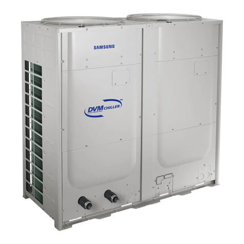
The DVM Chiller is an air to water heat pump
▪Chill water temperature range: 41°F to 77°F
▪Chill water temp down to 14°F with antifreeze
▪Hot water temperature range: 77°F to 131°F
▪Chiller ambient temperature operating range:
▪Cooling: 5°F to 118°F
▪Heating: -13°F to 109°F
▪10 ton and 15 ton nominal capacity models
▪208/230vac 3Ø and 460vac 3Ø models
▪Modular combinations from 20 to 240 nominal tons
▪Up to 16 units can be combined in one control group
▪Optional DMS 2.5 or Touch Central Controllers enable
control of 3rd party air handlers
▪No field installed refrigerant piping
DVM Chiller Overview
Model AG010 AG015
Water flow Range 16 ~ 48 gpm 17 ~ 68 gpm

DVM Chiller Introduction
7
DVM Chiller Overview
Hydro Side VRF Side
DVM Chiller Features
▪AG010(015)KSVAFH 208/230vac 3Ø AG010(015)KSVAJH 460vac 3Ø models
▪Chiller unit consists of a VRF side including dual flash injected inverter scroll compressors and a Hydro side
▪Dual outdoor fans
▪Braze Plate heat exchanger
▪Leaving water temperature reset option (“Water Law” setting)
▪Water temperature & pressure sensors
▪Intelligent defrost operation
▪Monitors outdoor coil temperature and air flow differential to initiate defrost
▪Selectable snow accumulation removal setting
▪Sound rating 60dB (A)
▪Maximum operating water pressure: 145 psi
▪Compatible with Samsung centralized controls
▪Touch Controller, DMS 2.5, BACnet & LonWorks Gateways
▪Dedicated module remote controller –MCM-A00N (required)

DVM Chiller Introduction
8
DVM Chiller Operation Patterns –System Design
Chiller system hierarchy overview
▪Unit –One DVM Chiller unit (10 or 15 ton)
▪Module –1 to 8 units connected together (required configuration)
1 Unit module 2 Unit module
Unit 0 Unit 1
4 Unit module
Unit 0 Unit 1 Unit 2 Unit 3
8 Unit module
Unit 0 Unit 1 Unit 2 Unit 3 Unit 4 Unit 5 Unit 6 Unit 7

DVM Chiller Introduction
10
DVM Chiller Operation Control Patterns
Selectable chiller group operation control patterns
Standard Control –Applications with high cooling/heating load factors
▪All modules in the group start simultaneously
▪Individual unit capacity control is based on the water outlet temperature sensor of each unit
▪As individual units reach setpoint temperature, they go into thermo-off
▪Factory default setting
Start OPERATION
All units will start at the same time. Each unit controls capacity based on its water
outlet temperature When units that have reached set
temperature will go into Thermo-Off (idle)
Close to set point
capacity control Thermo-Off
capacity control capacity control
Unit 0 Unit 1 Unit 2 Unit 3 Unit 0 Unit 1 Unit 2 Unit 3

DVM Chiller Introduction
11
DVM Chiller Operation Control Patterns
Selectable chiller group operation control patterns
Rotation Control –Applications with lower loads at system startup and with small load fluctuations
▪Chiller’s water outlet temperature is controlled based on the average temperature of all units in the module
▪The module with the highest priority starts first. When the module reaches full load, the next module with the next priority starts
▪When the module with the lowest priority operates at minimum capacity and the water outlet temperature approaches set temperature,
compressors stop
▪Setting is enabled during commissioning
Unit 0 Unit 1 Unit 2 Unit 3
Module 1 Module 2
Unit 0 Unit 1 Unit 2 Unit 3
Module 1 Module 2
Operates the unit with the highest priority
Starting
When LWT is close to set point, the
unit with the last priority stops
Close to set point
Thermo-Off
When first unit reaches its full speed (80~140Hz)
and average LWT, another unit that has the
following priority will operate.
↑
↑
Operating

DVM Chiller Introduction
12
DVM Chiller Operation Control Patterns
Selectable chiller group operation control patterns
▪Efficiency Control –Applications where the controlled area has a low load
▪System capacity control uses an average leaving water temperature of all operating units in a module
▪Load response time is prioritized as system capacity is increased
▪Efficiency Control maintains compressor operating frequencies in the mid range frequencies (50 –80Hz)
▪Setting is enabled during commissioning
Start operating a unit with the
highest priority.
Starting
50 ~ 80Hz
When the RPM of first unit reaches
the most efficient level (60 ~ 80Hz),
It starts operating second unit.
50 ~ 80Hz
↑
↑
It turns on the next unit in order of
priority as cooling load increase. The
max. rpm is still limited below 50 ~ 80Hz.
Operating
↑
↑
As the cooing load changes, the RPM
of operating units will
increase/decrease at the same time.
↑
↑
↑
↑
↑
↑
↑
↑
When the RPM of operating units
are below 50Hz, it will turn off one
of the units with the lowest priority.
Close to set point
Thermo-Off
50Hz

DVM Chiller Introduction
13
DVM Chiller Operation Control Patterns
Water Law Control –Applications where efficiency is increased by resetting the leaving water
temperature based on outside ambient temperature or room temperature
▪When chiller is configured for standard water temperature range (default) the operating water
temperature range in cooling will not drop below 41°F
▪When chiller leaving water temperature is controlled by room temperature, a field supplied TP100
external sensor must be used or a signal from a BMS control
Ambient Temp.
Leaving Water. Set Temp.
AirCool1 AirCool2
TCool1
TCool2
Ambient Temp.
AirHeat1 AirHeat2
THeat1
THeat2
[Cooling Mode] [Heating Mode]
By Outside Temperature
Leaving Water. Set Temp.
[Cooling Mode]
Room Temp.
[Heating Mode]
RoomCool1 RoomCool2
TCool1
TCool2
Room Temp.
RoomHeat1 RoomHeat2
THeat1
THeat2
By Room Temperature
Leaving Water. Set Temp.

DVM Chiller Introduction
14
Water Law Control Example
Water Law temperature setting ranges (°F) Example
Water Law based on outside temperature –cool mode
As outdoor temperature rises, the water set temperature decreases
(TCool1 = 48°F, TCool2 = 40°F, AirCool1 = 60°F, AirCool2 = 90°F)
Ambient Temperature (°F)
Leaving Water. Set Temperature (°F)
AirCool1 AirCool2
TCool1
TCool2
48°
40°
60°90°
Option Range (°F) Notes
AirCool1 32 -68 OA temp. 1, cool mode
AirCool2 86 –104 OA temp. 2, cool mode
RoomCool1 59 –75.2 Room temp. 1, cool mode
RoomCool2 77 –98 Room temp. 1, cool mode
TCool1 14 -77 Water set temp. 1, cool mode
TCool2 14 -77 Water set temp. 2, cool mode
AirHeat1 -4 -41 OA temp. 1, heat mode
AirHeat2 50 -60 OA temp. 2, heat mode
RoomHeat1 59 –75.2 Room temp. 1, heat mode
RoomHeat2 77 -95 Room temp. 1, heat mode
THeat1 91.4 - 131 Water set temp. 1, heat mode
THeat2 91.4 - 131 Water set temp. 2, heat mode

DVM
Chiller
Chiller System Components

Chiller System Components
17
DVM Chiller –Refrigerant Cycle
s
E
s
s
OFM1
HX_M
AC
OS1
HX_IC
PS_H
E_EV
V_EV2
V_EB
V_HG
V_4W
V_AR
CV_D1
T_D1
T_S
T_CO
T_EI
T_EO
T_L
T_CT1
T_A
V_EV1
CV_D2
T_D2
PW_H1
IPMC1 IPMC2
E
T_S2
s
s
T_S1
PT_C
PT_C
RC
PS_L
FP
OFM2
HX_M
E
T_PI1 T_PI2
HX_PHE
PS_WI PS_WO
COMP1 COMP2
T_CT2
E_M1
V_OR1 V_OR2
E_M2
T_PO1 T_PO2
T_WI T_WO
E_PHE1 E_PHE2
HX_PHE
PW_H2
OS2
Water
E
E
▪PS = Pressure sensor
▪V = Valve
▪T = Temperature sensor
▪AC = Accumulator
▪RC = Receiver
▪PW = Pressure switch
▪OS = Oil separator
▪PT = Service port
▪E = EEV (Electronic Expansion Valve)
▪HX = Heat exchanger
▪HX PHE = Plate heat exchanger
▪IPMC = Intelligent Power Module
(inverter PCB cooler)
▪V 4W = 4-way reversing valve

18
DVM Chiller –Control
VRF Control Box K1 K2 K3 K4
▪HUB PCB communication
▪Communication PCB
▪Inverter Controller
▪Hydro Controller
▪EEPROM
▪Setting inverter control options
▪Auto & ManualAddressing
▪VRF status display
▪Main PCB communication
▪FAN PCB communication
▪EEV’s - 4-way valve –oil return
valves –bypass valves
▪Pressure & Temp sensors
1
Chiller System Components
Table of contents
Other Samsung Chiller manuals
Popular Chiller manuals by other brands

KKT chillers
KKT chillers vBoxX 6 Translation of the original operating manual

Elkay
Elkay ERC8-1B/2B installation instructions

Serene
Serene SC112N-A user manual

Daikin
Daikin EWWD J Series Installation, operation and maintenance manual

Carrier
Carrier 61AF operating instructions

Gree
Gree T1/R410A/50Hz Service manual