Samsung RHF025EE Series User manual

ENGLISH
ERV
(Energy Recovery Ventilator)
INSTALLATION
MANUAL
RHF025EE Series
RHF035EE Series
RHF050EE Series
RHF080EE Series
RHF100EE Series
ESPAÑOLFRANÇAISITALIANOPORTUGUÊSDEUTSCH
DB98-27512A(1)SE F I P D
RHF_025EE_IM_E_27512_1.indd 31 2007-04-18 ソタネト 5:44:02

E-2
Contents
PREPARATION
Safety Precautions ......................................................................................................... 3
Space Requirements .................................................................................................... 5
Installation Diagram ..................................................................................................... 7
External Dimension ...................................................................................................... 8
INSTALLING THE UNIT
Installing the Unit .......................................................................................................... 10
Electric Wiring ................................................................................................................. 11
Schematic Diagram ...................................................................................................... 14
Option Switches ............................................................................................................. 15
Connecting the Unit ..................................................................................................... 16
COPMPLETING THE INSTALLATION
Duct Connection ........................................................................................................... 26
Performance Graph ...................................................................................................... 27
Final Checks and Trial Operation ............................................................................ 29
RHF_025EE_IM_E_27512_1.indd 2 2007-04-18 ソタネト 5:43:26

E-3
ENGLISH
WARNING
This indicates the possibility of serious injury or death.
Do not install the unit
by yourself. Incorrect
installation of the unit could
cause injury due to fire,
electric shock and water
leakage or from the unit
falling. Consult a dealer or
a qualified installer.
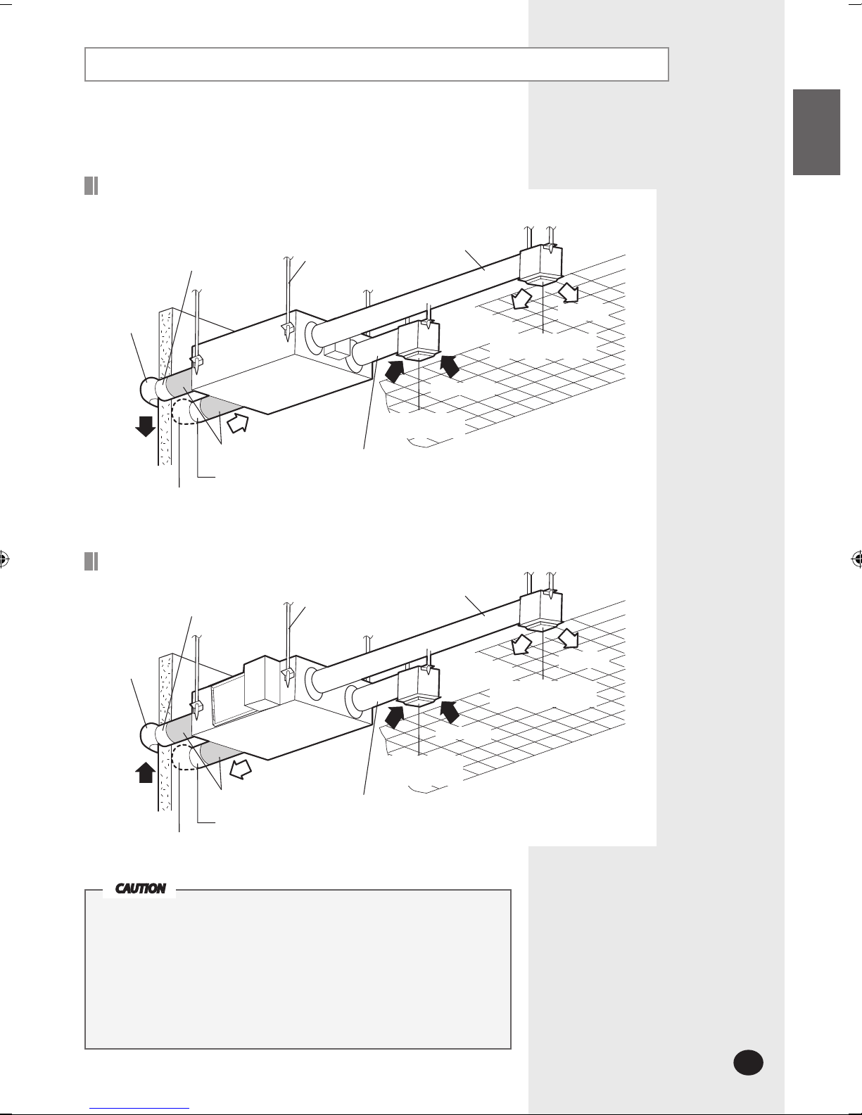
Hang down a blockage for
bird in front of outdoor air
suction duct. If something
such as bird’s nest blocks
the air suction duct, it may
result in oxygen shortage in
indoors.
Perform the installation
securely referring to the
installation manual.
Incomplete installation
could cause personal injury
due to fire, electric shock or
the unit falling.
Do not attempt to repair,
move, modify or reinstall
the unit on your own. Make
sure that these installations
are carried out by qualified
personnel to avoid electric
shock or fire.
Check if the voltage and
the frequency of the main
power supply are required
for the unit to be installed
and check the connection.
The electric work must be
done by service agent or
similarly qualified person
according to national wiring
regulations and use only
rated cable. If the capacity
of the electric work is not
properly completed, electric
shock or fire may occur.
Make sure the air intake is
located far from an exhaust
port of a burner. It may
cause oxygen shortage.
Ground the unit. Do not
connect the ground to a gas
pipe, water pipe, lighting
rod or telephone grounding.
Defective grounding could
cause electric shock.
Install the cables with
supplied cables firmly.
Fix them securely so that
external force is not to exert
to the terminal board.
If the connection or fixing is
incomplete, heat generation,
electric shock or fire may
occur.
Install separate MCCB and
ELB when installing the
power cable. If you do not
install the MCCB and ELB,
electric shock or fire may
occur.
If the power plug is
damaged, replace it by the
manufacturer or qualified
personnel to avoid the risk.
Disconnect the circuit
breaker when you don’t use
the product for a long period
of time to save energy.
Do not install the electric
wire to get tension to avoid
a hazard.
Unplug the product before
get repaired.
Do not pull the electric wire
or touch the power plug
with wet hands.
Installers are required to
read the general information
carefully for safety.
Do not put the product near
dangerous substances to
prevent fire, explosion or
injury and do not expose the
product to direct
sunlight.
Safety Precautions
Keep this installation manual together with the user’s manual in a handy place so that you can find it whenever
you need to see it after reading this manual thoroughly.
Make sure to read the following safety precautions carefully before installation.
Make sure to observe the cautions specified in this manual.
Conduct a test run of the unit after installation and then explain all system functions to the owner.
The indications and meanings are as shown below.
RHF_025EE_IM_E_27512_1.indd 3 2007-04-18 ソタネト 5:43:26

E-4
CAUTION
This indicates the possibility of serious injury or damage to environments when
operated incorrectly.
Install the unit in a place
where it is strong enough to
hold the product weight.
When installed in place
where it is not strong
enough to withhold the
product weight, the unit
may fall and cause injury.
Install the product inside
heat insulation over the
ceiling not to be contacted
with the outside air.
If the product is installed
out of the insulation, it may
result in electric shock or
malfunction due to moisture
generated in the product.
Do not install the product
in a place where it is
exposed to inflammable gas
leakage.
Do not install the product
in humid place such as
bathroom. It may cause
electric shock or malfunction.
Make sure to use the part
provided or specified parts
for the installation work. The
use of defective parts could
cause injury, fire, electric
shock or the unit falling, etc.
Do not install the product
in the place where exposed
to sulfurous acid or steam
because it may damage the
parts or cause malfunction.
Do not install the product in
the place where generates
toxic gas such as chemical
factory. It may cause fire or
gas poisoning.
Check the product for
damage that may have
taken place during
transportation and do not
install or use damaged
equipment.
All of the manufacturing and
packaging material used for
your new appliance are
compatible with the
environment and can be
recycled.
Dispose of the packaging
material in accordance with
the local requirements.
Install a ground leakage
breaker depending on the
installation place (where it is
humid). If not, it may cause
electric shock.
The product must be
installed according to the
national electrical
regulations.
The maximum input
power and current is
measured according to the
IEC Standard and the input
power and current is
measured according to
ISO standard.
WARNING
This indicates the possibility of serious injury or death.
Avoid the use of an
extension cord and do not
share the power outlet
with other appliances.
Incomplete connection,
defective insulation or
exceeding the permissible
current may cause electric
shock or fire.
Make sure to turn off the
main power when setting up
the product’s electric circuit
or power cords. There is
electric shock.
The product should be
installed in accordance with
the National Electrical
regulations.
Ensure that the national
safety code requirements
have been followed for the
main supply circuit. Ensure
that a properly sized and
connected ground wire is in
place.
RHF_025EE_IM_E_27512_1.indd 4 2007-04-18 ソタネト 5:43:27

E-5
ENGLISH
Space Requirements
The ventilator should be installed in a ceiling which has enough space
above as seen in the picture.
Exhaust Air
Supply Air
Outdoor Air
Heat exchange element
Body
Inspection hole
(for filter, heat exchange element,
fan, motor and damper)
Return Air
600mm
025
RHF_025EE_IM_E_27512_1.indd 5 2007-04-18 ソタネト 5:43:27

E-6
Space Requirements (Continued)
Body
Space for repairing
Exhaust Air
Supply Air
Outdoor Air
Heat exchange element
Inspection hole
(for filter, heat exchange element,
fan, motor and damper)
Return Air
The ventilator should be installed in a ceiling which has enough space
above as seen in the picture.
Model 'A' 'B' Number of heat exchange elements
035/050 1000 600
2
080/100 1135 800
Model 'A'
035/050 320
080/100 440
035/050/080/100
'A'mm 'B'mm
RHF_025EE_IM_E_27512_1.indd 6 2007-04-18 ソタネト 5:43:27

E-7
ENGLISH
Installation Diagram
Supply Air
Exhaust Air duct
Hood
Anchor bolt
Insulation
Outdoor Air suction duct
Hood
Exhaust Air Return Air duct
Air intake hole
(Air exhaust grille)
Return Air
Air discharging hole
(Air exhaust grille)
Supply Air duct
Supply Air
Exhaust Air duct
Hood
Anchor bolt
Insulation
Outdoor Air suction duct
Hood
Outdoor Air Return Air duct
Air intake hole
(Air exhaust grille)
Return Air
Air discharging hole
(Air exhaust grille)
Supply Air duct
025
035/050/080/100
Install the unit in a place where it is strong enough to hold the product
weight.
Install the unit in a place where the space is enough to install or repair
the unit.
Do not install the unit in humid place such as bathroom.
Do not install the unit in a place over 40°C or where exposed to fire,
gasoline or smoke directly.
Install the cables with supplied ones securely.
CAUTION
RHF_025EE_IM_E_27512_1.indd 7 2007-04-18 ソタネト 5:43:28

E-8
External Dimension
No. Name Quantity
Maintenence cover 1
Heat exchange element 1
Dust filter 2
Hanger 4
Electrical component box 1
Nominal diameter for duct : Ø150mm
(Unit : mm)
Model A B C E F G H I J K M N P Q R
025 600 660 70 510 675 729 102 470 85 98 242
Ø
140
Ø
156 133 350
Exhaust Air Supply Air
Outdoor Air Return Air
Ensure the space for installing and repairing.
025
RHF_025EE_IM_E_27512_1.indd 8 2007-04-18 ソタネト 5:43:28

E-9
ENGLISH
External Dimension
No. Name Quantity
Maintenence cover 1
Heat exchange element 2
Dust filter 4
Hanger 4
Electrical component box 1
Exhaust Air
Outdoor Air
Return Air
Supply Air
Model A B C E F G H I J K M N P
035/050 1000 1012 99 940.6 1036.4 26 130 617 253 135 270 Ø194 Ø241.5
080/100 1135 1220 84 1110 1183 25 184 613.25 387.75 170 340 Ø244 Ø270
(Unit : mm)
Ensure the space for installing and repairing.
035/050/080/100
Model
Nominal diameter for duct
035/050
Ø
200
080/100
Ø
250
(Unit : mm)
RHF_025EE_IM_E_27512_1.indd 9 2007-04-18 ソタネト 5:43:28

E-10
Installing the Unit
Make sure to attach the unit firmly. If the unit is not attached firmly or attached
incorrectly, it may result in malfunction or injury.
1Insert bolt anchors to a ceiling. Use existing ceiling support or construct
a suitable support.
2Install the suspension bolts depending on the ceiling type.
3Screw two nuts to the suspension bolts making space for hanging the unit.
4Hang the unit horizontally to the suspension bolts between two nuts.
5Fasten the nuts to suspend the unit.
The washer should be fit for the hanger.
Suspension bolt
(Ø10~Ø12)
Nut
Washer
Hanger
Washer
Nut
Rubber
Rubber
Fasten the nut
Ensure that the ceiling is strong enough to support the weight of the unit.
Before hanging the unit, test the strength of each attached suspension bolt.
CAUTION
Nut
RHF_025EE_IM_E_27512_1.indd 10 2007-04-18 ソタネト 5:43:29

E-11
ENGLISH
Electric Wiring
Before electric wiring, make sure that the voltage is 1 wire 220V/50Hz.
025
Electrical Component Box
Surface
035/050/080/100
Hanger
Fixing part
of wires
Maintenance cover
Electrical component box
Wiring outlet
Transmitter
PBA
Grounding
Electrical component box
Fixing part
of wires
Maintenance cover
Inside
Hanger
RHF_025EE_IM_E_27512_1.indd 11 2007-04-18 ソタネト 5:43:30

E-12
Electric Wiring
Electric Wiring (Continued)
1
Remove the 4 screws on the electrical component box and open the cover plate.
2Connect the cables correctly as seen in the picture.
Fix the cables with a cable tie.
3Connect the cable to the terminal board with a compressed ring terminal.
Fix the screws in the electrical component box with designated torque
referring to the table.
Size M5 Bolt M6 Bolt
Recommended size
N·m 1.34~2.0 1.67~2.5
kgf·cm 13.4~20.0 16.7~25.0
Connect to ERV wired remote control
Connect to power supply wire
Fixing part of electrical wires
Compressed ring terminal
Cable
Electrical component box
Screw
Screw
Electrical component box Cable fixation
Maintenence cover
Do not wash the heat exchange element. It may decrease the efficiency.
Make sure to use rated cable for power supply and do not extend or cut
the cord.
The unit should be installed in accordance with the National Electrical
regulations. Ensure that the national safety code requirements have been
followed for the main supply circuit.
CAUTION
RHF_025EE_IM_E_27512_1.indd 12 2007-04-18 ソタネト 5:43:31

E-13
ENGLISH
Electric Wiring (Continued)
Main PCB
② ③ ④ ⑤
⑥
⑦
⑧
⑨
⑩
⑪
①
No. Classification Explanation Specifications
1 DISPLAY DISPLAY
2
CO2 sensor
CO2 sensor connection port 3PIN (CN43)
3 Temperature sensor Indoor/outdoor temperature sensor connection port 4PIN (CN41)
4 Damper switch Signal input port of damper switch 3PIN (CN51)
5 External control On/Off control by external contact signal 2PIN (EXT1) / 2PIN (EXT2) /
2PIN (EXT3)
6 ERV wired remote control V1, V2 (DC 12V power supply),
F3,F4 (ERV wired remote control communication) 4PIN (TB±COM)
7 Communication F1, F2 (Communication between the ventilators or transmitter) 2PIN (TB±COM)
8 Monitor the operation status Report operation errors 4PIN (CN77)
9 Damper motor Damper control port for changing operation modes 2PIN (CN72)
10 External device External humidifier/ External heater/ External damper 4PIN (TB±LOAD)
11 Power supply 220V/50Hz(L/N) 2PIN (TB±LOAD)
RHF_025EE_IM_E_27512_1.indd 13 2007-04-18 ソタネト 5:43:31

E-14
Schematic Diagram
025/035/050
080/100
RHF_025EE_IM_E_27512_1.indd 14 2007-04-18 ソタネト 5:43:33

E-15
ENGLISH
Option Switches
The default setting of all switches is ON.
If you want to set the function on, turn OFF the switch.
DIP Switch Function ON OFF
SW05
K5 Spare - -
K6 Centralized control Not use Use
K7 Spare - -
K8 MASTER/SLAVE SLAVE MASTER
SW06
K9
CO2 sensor
Not use Use
K10 Filter signal display 2000 Hr 1000 Hr
K11 External control Refer to the table below
K12
SW07
K13 External humidifier Not use Use
K14 External heater Not use Use
K15 External damper Not use Use
K16 Spare - -
K5 (Spare)
K6 (Centralized control)
ON: Not use of centralized controller
OFF: Use of centralized controller
K7 (Spare)
K8 (MASTER/SLAVE)
ON: Communicate COM1(F1, F2), operating as SLAVE
OFF: Communicate COM2(F1, F2), operating as MASTER
K9 (CO2 sensor)
ON: Not use of external CO2 sensor
OFF: Use of external CO2 sensor
K10 (Filter signal display)
ON: Display filter reset after 2000 of running hours
OFF: Display filter reset after 1000 of running hours
K11, K12 (External control)
Setup control level of the ERV wired remote control and external control
K13 (External humidifier)
ON: Not use of external humidifier
OFF: Use of external humidifier
K14 (External heater)
ON: Not use of external heater
OFF: Use of external heater
K15 (External damper)
ON: Not use of external damper
OFF: Use of external damper
K16 (Spare)
K5 K6 K7 K8
SW05
K9 K10 K11 K12
SW06
K13 K14 K15 K16
SW07
K11 K12 External control setup
ON ON
Same level control with the
ERV wired remote control and
external control (Followed by
the last control status.)
ON OFF
Priority to the ERV wired
remote control
(While operating by the ERV
wired remote control, it can
not be controlled by the
external control. The external
control is possible only when
the ventilator is turned off.)
OFF ON
Priority to the external control
(While operating by the
external control, it can not be
controlled by the ERV wired
remote control. The ERV wired
remote control can control
only when the ventilator is
turned off.)
OFF OFF
Not use
K11, K12 (External control)
RHF_025EE_IM_E_27512_1.indd 15 2007-04-18 ソタネト 5:43:43

E-16
Connecting the Unit
Make sure to disconnect the power cable and power supply before connecting
the ventilator to other control solutions. If not, it may cause malfunction due to
electrical interference.
It does not need to connect the transmitter in case of individual control. Connect
the transmitter to the MASTER ventilator only, in case of centralized control.
1 Attach the transmitter to the case in the electrical component box.
2Connect the V1, V2 terminal of the transmitter to the V1, V2 terminal of the
ventilator PCB. (DC 12V)
3Connect the F1, F2 terminal of the transmitter to the F1, F2 terminal of the
ventilator PCB. (COM1 Communication)
Transmitter
1Remove the maintenence cover of the ERV wired remote control.
2Connect the V1, V2 terminal of the ERV wired remote control to the V1, V2
terminal of the ventilator PCB. (DC 12V)
3Connect the F1, F2 terminal of the transmitter to the F1, F2 terminal of the
ventilator PCB. (COM2 Communication)
4Reassemble the maintenence cover and the ERV wired remote control.
ERV Wired Remote Control
Transmitter
Ventilator
ERV Wired Remote Control
Ventilator
RHF_025EE_IM_E_27512_1.indd 16 2007-04-18 ソタネト 5:43:44

E-17
ENGLISH
Connecting the Unit
1Remove the maintenence cover of the ERV wired remote control.
2Connect the V1, V2 terminal of the ERV wired remote control to the V1, V2
terminal of the ventilator PCB. (DC 12V)
3Connect the F3, F4 terminal of the transmitter to the F3, F4 terminal of the
each ventilator PCB. (COM2 Communication)
4Reassemble the maintenence cover and the ERV wired remote control.
The ERV wired remote control is MASTER of COM2 communication, so it can
communicate without separate ADDRESS setting. Up to 16 ventilators can be
connected to a ERV wired remote control at once.
ERV Wired Remote Control and Multiple Ventilators
COM2 (F3, F4)
Ventilator Ventilator Ventilator Ventilator
DC 12V (V1, V2)
ERV Wired Remot Control
RHF_025EE_IM_E_27512_1.indd 17 2007-04-18 ソタネト 5:43:44

E-18
Connecting the Unit (Continued)
Centralized Controller
Installing the Centralized Controller
To use a centralized controller, set K6 of SW05 to OFF position.
- To centralized control, the ventilator should be set as MASTER among one
or more ventilators for communication.
MAIN SW01
ADDRESS
RMC SW02
ADDRESS
K5 K6 K7 K8
SW05
Setup Master Ventilator
1Set K8 of SW05 to OFF position.
2Set MAIN ADDRESS as 0,1,2 and also set RMC ADDRESS as 0,1,2 as well.
MAIN : Setup switch to designate the address among ventilators
RMC :
Setup switch to designate the address when controlling by
a centralized controller
Master Ventilator Ventilator Ventilator
Transmitter
Centralized Controller
MAIN:0
RMC:0
MAIN:1
RMC:1
MAIN:2
RMC:2
Indoor unit RMC ADDRESS
1 2 3 4 5 6 7 8 9 A B C D E F
Number on the centralized controller
1 2 3 4 5 6 7 8 9 10 11 12 13 14 15
MAIN SW01
ADDRESS
RMC SW02
ADDRESS
K5 K6 K7 K8
SW05
RHF_025EE_IM_E_27512_1.indd 18 2007-04-18 ソタネト 5:43:46

E-19
ENGLISH
Connecting the Unit (Continued)
Setup the Centralized Individual Control (1:1, Individual Room Control)
If the 00 switch of the centralized controller is set to ON position, the
ventilators which are designated 0 of their RMC ADDRESS are operated.
To centralized individual control, set each of the RMC ADDRESS of each
ventilator to different number which is controlled by a centralized controller.
Setup the Centralized Controller
Master Ventilator
Transmitter 0
Centralized Controller
Transmitter 1
Ventilator Ventilator Ventilator
MAIN:0
RMC:0
MAIN:1
RMC:1
MAIN:2
RMC:2
MAIN:3
RMC:3
Ventilator
MAIN:4
RMC:4
Master Ventilator
MAIN:0
RMC:5
Ventilator Ventilator Ventilator
MAIN:1
RMC:6
MAIN:2
RMC:7
MAIN:3
RMC:8
Ventilator
MAIN:4
RMC:9
RHF_025EE_IM_E_27512_1.indd 19 2007-04-18 ソタネト 5:43:48

E-20
Connecting the Unit (Continued)
Setup the Centralized Group Control (1:1 group, 16 Groups Control)
If the 00 switch of the centralized controller is set to ON position,
16 ventilators which are set as 0 of their RMC ADDRESS are operating
simultaneously. Up to 256 of ventilators can be controlled at once.
To centralized group control, set all of the RMC ADDRESS of all ventilators
to be controlled as the same number which is controlled by the centralized
controller.
Setup the Centralized Control (Continued)
Master Ventilator
Transmitter 0
Centralized Controller
Transmitter F
Ventilator Ventilator Ventilator Ventilator
MAIN:0
RMC:0
MAIN:1
RMC:0
MAIN:2
RMC:0
MAIN:3
RMC:0
Master Ventilator
MAIN:0
RMC:F
Ventilator Ventilator Ventilator Ventilator
MAIN:1
RMC:F
MAIN:2
RMC:F
MAIN:3
RMC:F
MAIN:F
RMC:0
MAIN:F
RMC:F
RHF_025EE_IM_E_27512_1.indd 20 2007-04-18 ソタネト 5:43:50
Other manuals for RHF025EE Series
2
This manual suits for next models
4
Table of contents
Other Samsung Fan manuals

Samsung
Samsung SER 450 User manual

Samsung
Samsung Fresh Access AN035NSEDAV/AA User manual

Samsung
Samsung MOS-C1 User manual

Samsung
Samsung VRF DVM S Water Instruction manual

Samsung
Samsung AN JSKLKN Series User manual

Samsung
Samsung ERV User manual

Samsung
Samsung RHF025EE Series User manual

Samsung
Samsung RHF025EE Series User manual

Samsung
Samsung RHF100KHEA Guide