Samsung DVD-905 User manual

DIGITAL VIDEO DISC PLAYER
DVD905
SERVICE
1. Precautions
2. Reference Information
3. Product Specifications
4. Disassembly and Reassembly
5. Thoubleshooting
6. Exploded Views and Parts List
7. Electrical Parts List
8.
Block Diagram
9. PCB Diagrams
10. Wiring Diagram
11. Schematic Diagrams
Manual
DIGITAL VIDEO DISC PLAYER CONTENTS
© Samsung Electronics Co., Ltd. MAY. 1997 AH68-20166A / AH68-20167A

Samsung Electronics 1-1
1. Precautions
1. Be sure that all of the built-in protective devices are
replaced. Restore any missing protective shields.
2. When reinstalling the chassis and its assemblies, be
sure to restore all pretective devices, including :
control knobs and compartment covers.
3. Make sure that there are no cabinet openings
through which people--particularly children
--might insert fingers and contact dangerous
voltages. Such openings include the spacing
between the picture tube and the cabinet mask,
excessively wide cabinet ventilation slots, and
improperly fitted back covers.
If the measured resistance is less than 1.0 megohm
or greater than 5.2 megohms, an abnormality exists
that must be corrected before the unit is returned
to the customer.
4. Leakage Current Hot Check (See Fig. 1) :
Warning : Do not use an isolation transformer
during this test. Use a leakage current tester or a
metering system that complies with American
National Standards Institute (ANSI C101.1,
Leakage Current for Appliances), and Underwriters
Laboratories (UL Publication UL1410, 59.7).
5. With the unit completely reassembled, plug the AC
line cord directly the power outlet. With the unitÕs
AC switch first in the ON position and then OFF,
measure the current between a known erath
ground (metal water pipe, conduit, etc.) and all
exposed metal parts, including : antennas, handle
brackets, metal cabinets, screwheads and control
shafts. The current measured should not exceed
0.5 milliamp. Reverse the power-plug prongs in the
AC outlet and repeat the test.
6. X-ray Limits :
The picture tube is designed to prohibit X-ray
emissions. To ensure continued X-ray protection,
replace the picture tube only with one that is the
same type as the original.
Fig. 1 AC Leakage Test
7. Antenna Cold Check :
With the unitÕs AC plug disconnected from the
AC source, connect an electrical jumper across the
two AC prongs. Connect one lead of the ohmmeter
to an AC prong.
Connect the other lead to the coaxial connector.
8. High Voltage Limit :
High voltage must be measured each time
servicing is done on the B+, horizontal deflection
or high voltage circuits.
Heed the high voltage limits. These include the
X-ray protection Specifications Label, and the
Product Safety and X-ray Warning Note on the
service data schematic.
9. Some semiconductor (Òsolid stateÓ) devices are
easily damaged by static electricity.
Such components are called Electrostatically
Sensitive Devices (ESDs); examples include
integrated circuits and some field-effect transistors.
The following techniques will reduce the
occurrence of component damage caused by static
electricity.
10. Immediately before handling sny semiconductor
components or assemblies, drain the electrostatic
charge from your body by touching a known
earth ground. Alternatively, wear a discharging
Wrist-strap device. (Be sure to remove it prior to
applying power--this is an electric shock
precaution.)
Device
Under
Test
(Reading should
not be above
0.5mA)
Leakage
Currant
Tester
Earth
Ground
Test all
exposed metal
surfaces
Also test with
plug reversed
(using AC adapter
plug as required)
2-Wire Cord

Precautions
1-2 Samsung Electronics
11. High voltage is maintained within specified limits
by close-tolerance, safety-related components and
adjustments. If the high voltage exceeds the
specified limits, check each of the special
components.
12. Design Alteration Warning :
Never alter or add to the mechanical or electrical
design of this unit. Example : Do not add
auxiliary audio or video connectors. Such
alterations might create a safety hazard. Also, any
design changes or additions will void the
manufacturerÕs warranty.
13. Hot Chassis Warning :
Some TV receiver chassis are electrically
connected directly to one conductor of the AC
power cord. If an isolation transformer is not
used, these units may be safely serviced only if
the AC power plug is inserted so that the chassis
is connected to the ground side of the AC source.
To confirm that the AC power plug is inserted
correctly, do the following : Using an AC
voltmeter, measure the voltage between the
chassis and a known earth ground. If the reading
is greater than 1.0V, remove the AC power plug,
reverse its polarity and reinsert. Re-measure the
voltage between the chassis and ground.
14. Some TV chassis are designed to operate with 85
volts AC between chassis and ground, regardless
of the AC plug polarity. These units can be safely
serviced only if an isolation transformer inserted
between the receiver and the power source.
15. Never defeat any of the B+ voltage interlocks.
Do not apply AC power to the unit (or any of its
assemblies) unless all solid-state heat sinks are
correctly installed.
16. Always connect a test instrumentÕs ground lead to
the instrument chassis ground before connecting
the positive lead; always remove the instrumentÕs
ground lead last.
17. Observe the original lead dress, especially near
the following areas : Antenna wiring, sharp
edges, and especially the AC and high voltage
power supplies. Always inspect for pinched, out-
of-place, or frayed wiring. Do not change the
spacing between components and the printed
circuit board. Check the AC power cord for
damage. Make sure that leads and components
do not touch thermally hot parts.
18. Picture Tube Implosion Warning :
The picture tube in this receiver employs
Òintegral implosionÓ protection. To ensure
continued implosion protection, make sure that
the replacement picture tube is the same as the
original.
19. Do not remove, install or handle the picture tube
without first putting on shatterproof goggles
equipped with side shields. Never handle the
picture tube by its neck. Some Òin-lineÓ picture
tubes are equipped with a permanently attached
deflection yoke; do not try to remove such
Òpermanently attachedÓ yokes from the picture
tube.
20. Product Safety Notice :
Some electrical and mechanical parts have special
safety-related characteristics which might not be
obvious from visual inspection. These safety
features and the protection they give might be
lost if the replacement component differs from the
original--even if the replacement is rated for
higher voltage, wattage, etc.
Components that are critical for safety are
indicated in the circuit diagram by shading,
( or ).
Use replacement components that have the same
ratings, especially for flame resistance and
dielectric strength specifications. A replacement
part that does not have the same safety
characteristics as the original might create shock,
fire or other hazards.
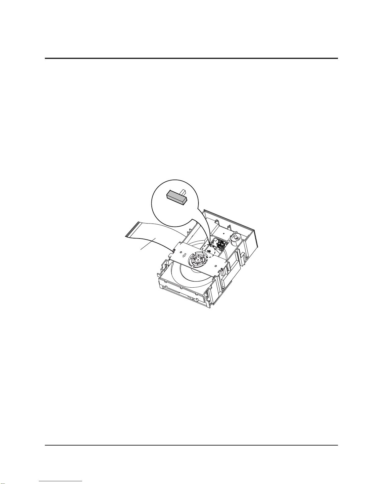
21. Cautions for handling Pick-up
Body grounding (hand) : Be sure to wear a wrist
strip with one side grounded. (Impedance :
Below 10-8 ½)
Work table grounding : Put A grounded electric
conductor such as copper plate on tne work
table.
Caution: Do not let clothing touch the product
(to prevent possible damage from static electric-
ty).
FPC operation : Handle the FPC carefully because
it is easily damaged.

Precautions
Samsung Electronics 1-3
1) Remove the power cable.
2) Switch LD SW3 on deck PCB to ÔSÕ before remov-
ing the FPC ( inserted into Main PCB CN1.
See Fig 1-2.)
3) Disassemble the deck.
4) Disassemble the deck PCB.
5) Replace the Pick-up.
OS
LD
SW3
FPC
1-2-1 Disassembly
1-2 Pick-up disassembly and ressembly
1-2-2 Assembly
Note :If the assembly and disassembly are not done in correct sequence, the Pick-up may be damaged.
Fig. 1-2
1) Replace the Pick-up.
2) Assemble the deck PCB.
3) Reassemble the deck.
4) Switch LD SW3 on deck PCB to ÔOÕ and insert
FPC into Main PCB CN1 (See Fig 1-2).

Precautions
1-4 Samsung Electronics
MEMO

Samsung Electronics 3-1
3. Product Specifications
The specifications and design may be changed without notice. The weight and dimensions are approximate.
MODEL DVD905
G
E
N
E
R
A
L
D
I
S
C
V O
I U
D T
E P
O U
T
A O
U U
D T
I P
O U
T
120 Voltage, 60Hz
23W
4.4Kg
(W)420mm x (D)339mm x (H)120mm
+ 5 °C ~ 35 °C
50% ~ 95%
Reading Speed ; 1.2 ~ 1.4mm/sec
Maximum Play Time ; 135 minutes
Reading Speed ; 1.2 ~ 1.4mm/sec
Maximum Play Time ; 74 minutes
Reading Speed ; 1.2 ~ 1.4mm/sec
Maximum Play Time ; 74 minutes
Reading Speed ; 1.2 ~ 1.4m/sec
Maximum Play Time ; 74 minutes(Video + Audio)
2 channel ; 1.0Vp-p
R(Red) ; 0.714Vp-p
G(Green) ; 0.714Vp-p
B(Blue) ; 0.714Vp-p
S(Sync) ; 4.0Vp-p
Luminance Signal ;1Vp-p (75Ωload)
Color Signal ; 0.286Vp-p (75Ωload)
L(1/L), R(2/R)
F/L, F/R, R/L, R/R, C/T, S/W
Analog ; 2Vrms(1KHz)
Digital ; 5Vp-p
* Frequency Response ; 4Hz ~20KHz, S/M Ratio : 105dB
* Dynamic Range ; 95dB
* Total Harmonic Distortion 0,005%
Power Requirements
Power Consumption
Weight
Set Size
Operating Temperature Range
Operating Humidity Range
DVD
(DIGITAL VERSATILE DISC
CD : 12cm
(COMPACT DISC)
CD : 8cm
(COMPACT DISC)
VIDEO - CD
12cm
RCA JACK
SUPER VIDEO
2 channel
5 channel
Output Level
Digital Frequency
Response

Product Specifications
3-2 Samsung Electronics
MEMO

Disassembly and Reassembly
1) Supply power and open Tray Œ.
2) Disassemble the door-tray ´in direction of arrow.
3) Close Tray Œand power off.
Note : If Tray ŒdoesnÕt open, insert a clip ˇinto the hole (as shown in detailed drawing), and open Tray Œ
manually.
Fig. 4-1
Samsung Electronics 4-1
70mm
TRAY
DOOR-TRAY
CHIP
2
1
3
4. Disassembly and Reassembly
4-1 Exterior and PCB Disassembly
4-1-1 Door-tray

4-2 Samsung Electronics
Disassembly and Reassembly
4-1-2 Top cabinet
1. Remove 3 screws Œon the back panel.
2. Remove 4 screws ´, ˇon the left and right side.
3. Lift up the top cabinet in direction of arrow.
Fig. 4-2
CABINET-TOP
2SCREWS 3SCREWS
2SCREWS
22
33
11

Samsung Electronics 4-3
Disassembly and Reassembly
4-1-3 Front
1. Remove 2 screws Œ, ´on the left and right side of panel-front assÕy
2. Remove 2 screws ˇ on the bottom of cover-panel assÕy and disassemble the front.
3. Remove 2 screws ¨from PCB-front.
4. Remove 9 hooks to fix PCB-front and disassemble PCB-front.
5. Remove 2 screws ˆon the top of cover-panel assÕy
6. Remove 4 top hooks Øand 5 bottom hooks ∏and disassemble the cover-panel assÕy.
Fig. 4-3
2 SCREWS
1 SCREW
4 HOOKS
2 SCREWS
COVER-PANEL ASS'Y
5 HOOKS
PANEL-FRONT ASS'Y
1 SCREW
2 SCREWS
PCB-FRONT
22
66
55
44
11
77
33

4-4 Samsung Electronics
Disassembly and Reassembly
4-1-4 PCB-MAIN, PCB-SMPS
1. Remove 4 screws Œto fix PCB-MAIN.
2. Remove 2 Holder-PCB ´inserted in PCB-MAIN and lift up PCB-MAIN.
3. Remove 3 screws ˇ from PCB-SMPS.
4. Remove 3 Spacer-PCB ¨inserted in PCB-SMPS and lift up PCB-SMPS.
5. Remove 2 screws ˆto fix BRKT-PCB assÕy.
Fig. 4-4
4 SCREWS
2 SCREWS
PCB-MAIN
PCB-SMPS
3 SCREWS
BRKT-PCB ASS'Y
HOLDER-PCB
SPACER-PCB
ASS'Y BOTTOM
11
55
22
44
33

Samsung Electronics 4-5
Disassembly and Reassembly
4-1-5 Deck, Frame-chassis
1. Remove 4 screws Œfrom the deck and lift it up.
2. Remove 4 screws ´from the frame-chassis and lift it up.
Fig. 4-5
4 SCREWS
DECK
FRAME-CHASSIS
4 SCREWS
11
22

Disassembly and Reassembly
4-6 Samsung Electronics
4-2 PCB Locations
PCB-MAIN
PCB-SMPS
PCB-FRONT
Fig. 4-6
DVD905

Disassembly and Reassembly
Samsung Electronics 4-7
4-2-1 DVD905
Fig. 4-7
PCB-FRONT
1
PCB-SMPS
4
2
6
PCB-MAIN
3
5
No. Connector wafer No. Direction Connector wafer No.
ŒFCN1 PCB-FRONT PCB-MAIN VCN11
´VCN11 PCB-FRONT FCN1
ˇCN5 DECK PCB-MAIN CN1
¨CN1 DECK CN5
ˆPCN02 PCB-SMP PCB-MAIN VCN13
ØVCN13 PCB-SMPS PCN02

Disassembly and Reassembly
4-8 Samsung Electronics
4-3 Deck Disassembly
4-3-1 Tray
1. Remove 2 screws Œand lift up the assÕy-deck clamper ´.
2. Insert a clip into Emergency hole, and push Gear-Cam Center ˇ. When the tray ¨ comes out a little, pull it in
direction of arrow ÒCÓ.
3. Pull the tray ¨ to disassemble, while simultaneously pushing the hook ˆ, Øin direction of arrow ÒAÓ, ÒBÓ.
Fig. 4-8
"A"
"C"
" B "
HOOK
EMERGENCY
HOLE
CLIP
33GEAR-CAM CENTER
TRAY
HOOK
112 SCREWS
ASS'Y-DECK CLAMPER
22
55
66
33
44

Disassembly and Reassembly
Samsung Electronics 4-9
4-3-2 Ass’y-Deck DVD
1. Remove 2 screws Œand disassemble the assÕy-PCB deck ´.
2. Disassemble the assÕy-deck DVD ¨in direction of arrow ÒBÓ, while simultaneously pushing the hook ˇ in
direction of arrow ÒAÓ.
Fig. 4-9
"B"
"A"
ASS'Y-DECK DVD
33HOOK
ASS'Y-PCB DECK
2 SCREWS
11
22
33
44

Disassembly and Reassembly
4-10 Samsung Electronics
4-3-3 Chassis-Main parts
1. Lift up the gear-tray Œ, remove 1 screw ´and lift up the gear-cam center ˇ.
2. Lift up the belt-pulley ¨, remove 1 screwˆand lift up the pulley-gear Ø.
3. Remove 1 screw ∏and lift up the gear-tray A ”and gear-cam sub ’.
4. Remove 2 screws ˝and disassemble the assÕy-motor load Ô.
5. Remove 1 screw and disassemble the lever-open S/W Ò.
6. Lift up the shaft-syncro Úand remove the 2 gear-syncro Æ in both directions.
Assembling : Adjust the shaft end of motor-feed so that it is exactly equal to the height of the hump in gear pole
of assÕy-gear magnet.
Fig. 4-10
GEAR-CAM CENTER
1 SCREW
GEAR-CAM SUB
11GEAR-TRY
GEAR-TRY A
BELT-PULLEY
1 SCREW
PULLEY-GEAR
2 SCREWS
LEVER-OPEN S/W
1 SCREW
MOTOR,PULLEY ASSEMBLING : ADJUST THE END OF MOTOR
SHAFT SAMELY AS HEIGHT OF PULLEY AT ASSEMBLY.
ASS'Y-MOTOR LOAD
GEAR-SYNCHRO
SHAFT-SYNCHRO
GEAR-SYNCHRO
GEAR-CAM SUB
1 SCREW
33GEAR-CAM-CENTER
POINT
1212
1313
1010
66
55
44
77
88
11
332299
33
99
1515
1414
1515
1111

Disassembly and Reassembly
Samsung Electronics 4-11
4-3-4 Ass’y deck
1. Remove 4 screws Œ.
2. Lift up the assÕy-deck ´.
Fig. 4-11
4 SCREWS
ASS'Y-DECK
11
22

Disassembly and Reassembly
4-12 Samsung Electronics
4-3-5 Ass’y-Deck parts
1. Remove 3 screws Œand disassemble 3 holder-cams ´.
2. Disassemble the rack-slide ˆand assÕy-pickup Ø, while simultaneously removing the shaft-P/U-L ¨,
shaft-P/U-R ¨.
3. Remove 3 screws ∏and disassemble the assÕy-motor spindle ”.
4. Remove the washer-plain ’and disassemble the assÕy-gear feed AU/AL ˝.
5. Remove the washer-plain Ôand disassemble the gear-feed B .
6. Remove the washer-plain Òand disassemble the assÕy-gear feed CU/CL Ú.
7. Disassemble the assÕy-gear magnet Æ.
8. Remove 2 screws ıand disassemble the assÕy-PCB hall sensor ˜.
9. Remove 1 screw ¯and disassemble the motor-feed ˘.
Assembling : Adjsut the shaft end of motor-feed ˘ so that it is exactly equal to the height of the hump in gear
pole of assÕy-gear magnet.
Fig. 4-12
HUMP
MOTOR SHAFT
<DETAILED DRAWING : UPPER SIDE>
HOLDER-CAM
3 SCREWS
ASS'Y-MOTOR
SPINDLE
3 SCREWS
SHAFT-P/U-L
ASS'Y-PICKUP
MOTOR-FEED
1 SCREWS
ASS'Y-PCB HALL SENSOR
2 SCREWS
ASS'Y-GEAR MAGNET
ASS'Y-GEAR FEED AU/AL
WASHER-PLANE
GEAR FEED B
WASHER-PLANE
ASS'Y-GEAR FEED CU/CL
WASHER-PLANE
SHAFT-P/U-R
RACK-SLIDE
1818
1919
1717
1616
1515
1414
99
1212
1111
1414
1313
55
44
66
33
77
88
11
22

Samsung Electronics 2-1
2-1-1 Comparison between linear power supply and SMPS
2-1-1(a) LINEAR
Fig. 2-1
Input : Common power to transformer(Vp)
Fig. 2-2
The output Vs of transformer is determined by the ratio of
1st Np and 2st Ns.
Vs = (Ns/Np) x Vp
Fig. 2-3
Vout is output (DC) by diode and
condensor.
Fig. 2-4
2. Circuit Operating Description
2-1 SMPS circuit description
Vreg
Vout
+
–+
+
–Vs
(Ns)
Vp
(Np)
Regulator
Common power
(Ex.220V60Hz)
Vs
t
0
220 2 V
20us
Vs
t
0
Vout
t
0
3Waveform/Description
Other manuals for DVD-905
2
Table of contents
Other Samsung Turntable manuals
Popular Turntable manuals by other brands

Pro-Ject Audio Systems
Pro-Ject Audio Systems Elemental Instructions for use

Pioneer
Pioneer PL-225 operating instructions

Pyle Pro
Pyle Pro Vintage PVTT2U user manual

Silicon Chip
Silicon Chip Music HALL mmf-1.3 manual

Pro-Ject Audio Systems
Pro-Ject Audio Systems Debut RecordMaster II Instructions for use

Alecto
Alecto BLX-10 user manual