Str ight Action H nd Tool CAT-HT-246-1416-11 STS-M-246-1416-11-A
2
of 4 SAMTEC
All International Rights Reserved. CUSTOMER SERVICE 1-800-SAMTEC9
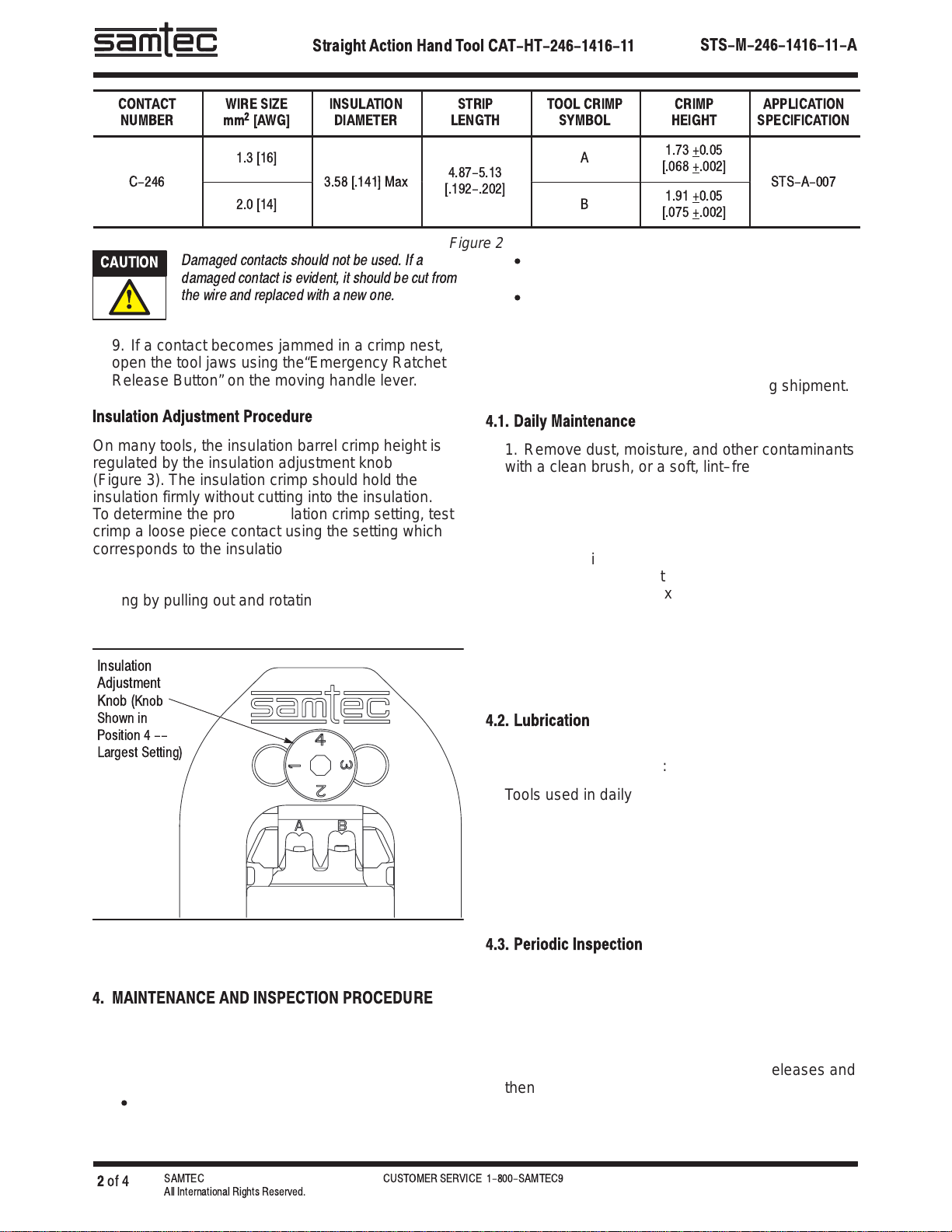
CONTACT
NUMBER WIRE SIZE
mm2[AWG] INSULATION
DIAMETER STRIP
LENGTH TOOL CRIMP
SYMBOL CRIMP
HEIGHT APPLICATION
SPECIFICATION
1.3 16]
4.87-5.13 A1.73 +0.05
.068 +.002]
-
2.0 14]
.
.
.192-.202] B1.91 +0.05
.075 +.002]
-
-
Figure 2
Damaged contacts should not be used. If a
damaged contact is evident, it should be cut from
the wire and replaced with a new one.
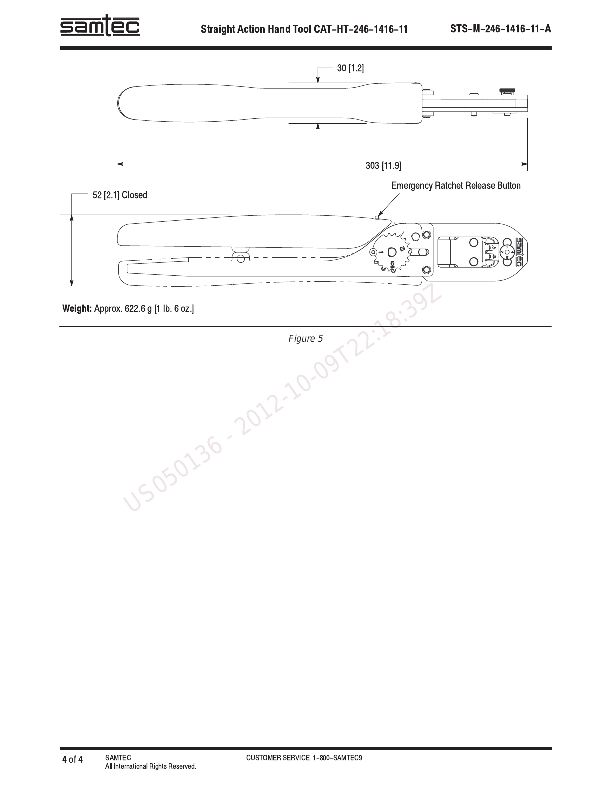
9. If a contact becomes jammed in a crimp nest,
open the tool jaws using the“Emergency Ratchet
Release Button” on the moving handle lever.
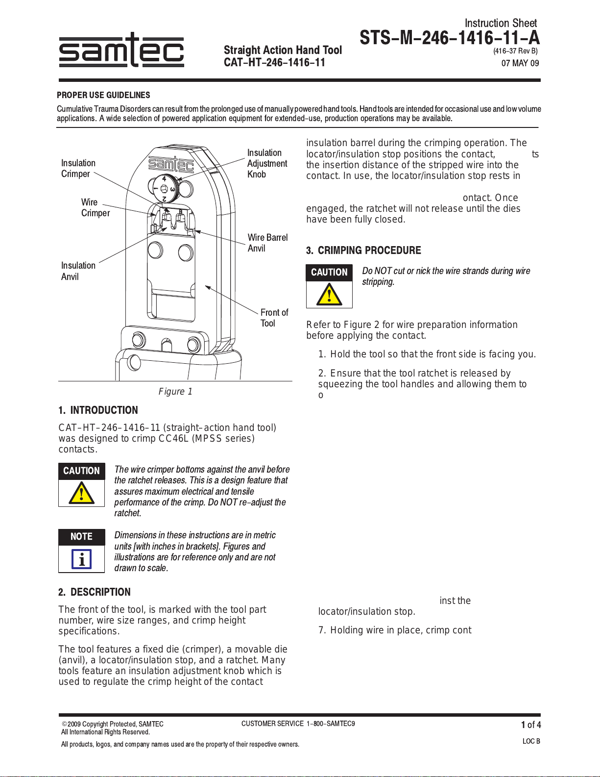
Insul tion Adjustment Procedure
On many tools, the insulation barrel crimp height is
regulated by the insulation adjustment knob
(Figure 3). The insulation crimp should hold the
insulation firmly without cutting into the insulation.
To determine the proper insulation crimp setting, test
crimp a loose piece contact using the setting which
corresponds to the insulation diameter: (1) –– small;
(2) and (3) –– medium; or (4) –– large. If the crimped
insulation barrel is too tight or loose, change the
setting by pulling out and rotating the adjustment
knob to the desired setting.
Figure 3
Insulation
Adjustment
Knob (Knob
Shown in
Position 4 --
Largest Setting)
4. MAINTENANCE AND INSPECTION PROCEDURE
It is recommended that a maintenance and inspection
program be performed periodically to ensure
dependable and uniform terminations. Frequency of
inspection depends on:
S
The care, amount of use, and handling of the
hand tool,
S
The presence of abnormal amounts of dust and
dirt,
S
Your own established standards.
The hand tool is inspected before being shipped;
however, it is recommended that the tool be inspected
immediately upon its arrival at your facility to ensure
that the tool has not been damaged during shipment.
4.1. D ily M inten nce
1. Remove dust, moisture, and other contaminants
with a clean brush, or a soft, lint–free cloth. Do not
use objects that could damage the tool.
2. Make certain that the retaining pins are in place
and that they are secured with retaining rings.
3. All pins, pivot points, and bearing surfaces
should be protected with a thin coat of any good
SAE 20 oil. Do not oil excessively.
4. When the tool is not in use, keep handles closed
to prevent objects from becoming lodged in the
crimping jaws.
5. Store the tool in a clean, dry area.
4.2. Lubric tion
Lubricate all pins, pivot points, and bearing surfaces
with SAE 20 oil as follows:
Tools used in daily production – lubricate daily
Tools used daily (occasional) – lubricate weekly
Tools used weekly – lubricate monthly
Wipe excess oil from tool, particularly from crimping
area. Oil transferred from the crimping area onto
certain terminations may affect the electrical
characteristics of an application.
4.3. Periodic Inspection
1. The hand tool may be immersed (handles
partially closed) in a reliable commercial
degreasing compound (suitable for plastics) to
remove accumulated dirt, grease and foreign
matter.
2. Close tool handles until the ratchet releases and
then allow the handles to open freely. If they do not
open quickly and fully, the spring is defective and
must be replaced.
CAUTION
!
US050136 - 2012-10-09T22:18:39Z