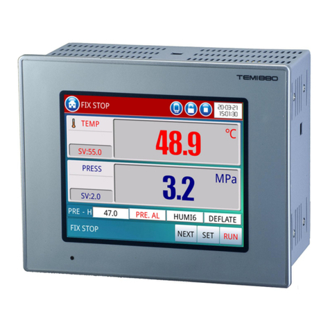
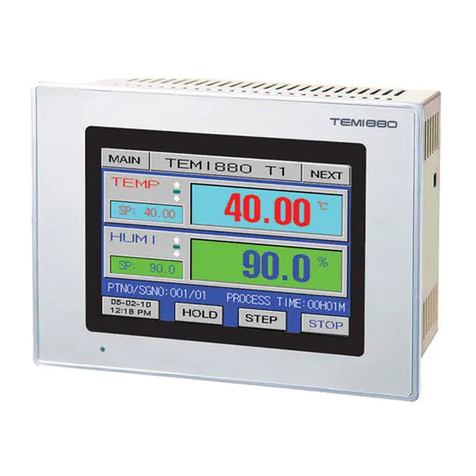
Samwontech TEMP880S Quick start guide

THERMAL SHOCK TEST CONTROLLER
TEMP880S
INSTRUCTION MANUAL

SAMWONTECH
1st Edition of TEMP880S IM : Sep. 21. 2005 Page 1 / 1
TABLE
1Installation Instruction
1.1 Instructions(Cautions) for Safety ………………………………………………………………………… 1
1.2 The exterior inspection and accessories identification ………………………………………………… 3
1.3 Installation ……………………………………………………………………………………………………… 5
1.4 Wiring …………………………………………………………………………………………………………… 9
2Instruction Manual
2.1 Setting Button ………………………………………………………………………………………………… 18
2.2 How to Enter Setting Value ……………………………………………………………………………… 20
2.3 General Operation Setting Flow Chart ………………………………………………………………… 21
2.4 Initial Screen ………………………………………………………………………………………………… 22
2.5 Main Screen ………………………………………………………………………………………………… 23
2.6 Operation Screen …………………………………………………………………………………………… 24
2.6.1 Program stop screen …………………………………………………………………………………… 24
2.6.2 Program preparation screen …………………………………………………………………………… 28
2.6.3 Program operation screen …………………………………………………………………………… 30
2.7 Motion Setting Screen ……………………………………………………………………………………… 33
2.8 Reserve Set Screen………………………………………………………………………………………… 36
2.9 Graph and Graph Record Set Screen …………………………………………………………………… 37
2.10 Pattern Set Screen ………………………………………………………………………………………… 39
2.10.1 File edit screen ………………………………………………………………………………… 42
2.10.2 Time signal setting screen ……………………………………………………………………… 43
2.10.3 Pattern name set …………………………………………………………………………………… 45
2.11 Display Set ……………………………………………………………………………………………… 46
2.12 System Setting Screen …………………………………………………………………………………… 47
2.12.1 Input and input revision for sections………………………………………………………… 48
2.12.2 Control output and transmission setting screen ……………………………………………… 53
2.12.3 Inner signal setting screen ………………………………………………………………………… 57
2.12.4 PID set screen ………………………………………………………………………………………… 59
2.12.5 DO CONFIG setting screen ……………………………………………………………………… 63
2.12.6 Alarm and DI error name setting screen ……………………………………………………… 66
2.12.7 Communication set screen ………………………………………………………………………… 69
2.12.8 Initial display and status display lamp set ………………………………………………………… 70
2.13 Password Input Screen ……………………………………………………………………………………… 72
3Parameter Setting Table ……………………………………………………………………………………… 73
4Communication Manual
4.1 Communication Specification ……………………………………………………………………………… 79
4.2 Communication Wiring ……………………………………………………………………………………… 80
4.3 Communication COMMAND………………………………………………………………………………… 81
4.4 D-REGISTER Explanation ………………………………………………………………………………… 89
▪ D-REGISTER TABLE…………………………………………………………………………………………… 96

SAMWONTECH
1st Edition of TEMP880S IM : Sep. 21. 2005 Page 1 / 101
※This is a manual for a Thermal Shock Test Controller(TEMP880S).
1. Installation Instruction
1.1 Instructions(Cautions) for Safety
Thank you for purchasing our Thermal Shock Test Controller(TEMP880S).
This instruction manual explains how to install and use the product.
음Safety Symbol Mark
(A) Represents “Handle with care” or “Caution.” It may cause death, serious injuries, or
damages on the machine if it is violated.
(1) Product : It represents the matters for the protection of the user and product.
(2) User’s manual: In order to prevent the user from receiving electric shocks, it
describes the matters that demand special attention.
(B) Represents a “Grounding Terminal”.
Please make sure the product is earthed when installing and using.
(C) Represents “Additional explanation”
Describes supplementary explanation.
(D) Represents “Reference”.
☞ Describes referential explanation and reference page.
음Cautions for the manual음
(A) Make sure the final users keep this manual, and place it at which it can be easily found.
(B) Use the product after having through full knowledge of the manual.
(C) This manual describes function of the product specifically, and does not warrant matters that
(C) are not included in the manual.
(D) The user should not edit or photo copy any part of the manual without notice.
(E) Some matters on the manual may be changed without notice.
(F) If any errors suchb as poor parts, misexplanation, or omission are found on the manual, please
(C) contact where it was purchased or the business department.

SAMWONTECH
1st Edition of TEMP880S IM : Sep. 21. 2005 Page 2 / 101
음 Caution for the product safety and remodeling음
(A) For the protection and safety of the product and system connected to it, use the product after
(A) having through full knowledge of the manual.
(B) The company is not liable for any damages caused by actions that are inconsistent with the (A)
(A) manual’s instruction or carelessness.
(C) For the protection and safety of the product and system connected to it, install additional (A)
(A) protection or safety circuit on the outside of the product. Interior remodeling or any changes are
(A) forbidden. (가)
(D) Do not disassemble or remodel. It causes electric shocks, fire, or malfunctioning.
(E) When changing the product parts or supplies, contact our company’s business department.
(F) Inflow of moisture may cause malfunctioning.
(G) A deep impact on the product may cause damages and malfunctioning of the product.
음Exemption from Responsibility음
(A) The company is not liable for any warranty or obligations that are not specified in quality (A) (A)
(A) guarantee qualification of the company.
(B) The company is not liable for any direct or indirect harm of the user or third person, which are
(A) caused by unexpected defect or natural disaster.
음Quality guarantee qualification음
(A) The product is under warranty for one year from purchase. For damages occurred under normal
(A) circumstances as stated in the manual, the product will be repaired without cost.
(B) For damages occurred when the warranty is invalid, it will be repaired under the company (A)
(A) standard at cost.
(C) For the following circumstances, repair is offered at cost even if damages occurred during (A)
(A) warrant period.
(1) Breakdown from user’s mistake or fault (Ex: Initialization due to loss of password)
(2) Breakdown from a natural disaster (Ex: fire, flood, and etc.)
(3) Breakdown from moving after install
(4) Breakdown from disassembling, remodeling or damaging
(5) Breakdown from power supply such as unstable electricity
(6) And others.
(F) Contact the company’s business department if any repair is needed.

SAMWONTECH
1st Edition of TEMP880S IM : Sep. 21. 2005 Page 3 / 101
1.2 The exterior inspection and accessories identification
▶ Check the exterior of the product to make sure the product is not damaged when it is first purchased. ▶
▶ Also, check the following matters.
1.2.1 Features of ordered product confirmation
▶ Confirm the obtained product is identical with what you order.
▶ How to confirm: Confirm feature code of label on the right side of the box or left side of the product ▶
▶ case.
Model Feature
Code
Appendix
Code UDC Contents
- 1 I/O1 BOARD (10 POINT : basis)
→ 24V SMPS internally equipped
- 2
I/O2 BOARD (10 POINT : addition)
0 RS232C (basis)
1
RS485 (option)
TEMP880S
/UDC UDC100 (option)
☞ In the case of generic model, the code is TEMP880S-10 (I/O 10POINT + RS232C).
1.2.2 Contents confirmation
▶ Confirm the following contents are included.
TEMP880S mainframe Fixed mount Manual
I/O1 BOARD + 30 Pin Cable
→ 24V SMPS included(RELAY driving)
I/O2 BOARD + 14 Pin Cable
→ Included only for TEMP880S-20 or -21

SAMWONTECH
1st Edition of TEMP880S IM : Sep. 21. 2005 Page 4 / 101
1.2.3 Processing of damaged product
▶ Contact where the products are purchased or the company’s business department if you find any
▶ missing or damaged parts.
▶ Check replacement period for the following non-durable parts and replace them before the
▶ period exceeds.
■ FUSE SR-5:630mA/250VAC equivalent product : semi-permanent
■ BACKLIGHT : 10,000 ~ 15,000 HOUR
■ RELAY JQ1P-DC24V equivalent product : less than ON/OFF 300,000 times
■ BATTERY ER3VT(3.6V) 1/2AA equivalent product : less than 200,000 HOUR
☞ For batteries, use the identical product or the ones with same capacity to prevent explosion.
☞ Also, separate used batteries from other garbage when you dispose them.
Lifetime of the parts in the controller

SAMWONTECH
1st Edition of TEMP880S IM : Sep. 21. 2005 Page 5 / 101
1.3 INSTALLATION
1.3.1 INSTALLATION PLACE AND ENVIRONMENT
음Cautions for installment place and environment
(A) To prevent from getting electric shocks, turn on the product after it is installed on the panel.
(B) Do not install the product under the following environment.
■ Place where people can touch the ground connection without noticing.
■ Place exposed directly to machinery vibration or shock.
■ Place exposed to corrosion or combustion gas.
■ Place where temperature fluctuates intensely.
■ Place where temperature is extremely high(over 50℃) or low (below 10℃)
■ Place exposed to the direct sun ray.
■ Place affected a lot by a electric wave.
■ Humid place (humidity is over 85%)
■ Place where keeps inflammable things.
■ Place where contains a lot of dust or salt.
■ Place affected a lot by an ultraviolet ray.
☞ Even though the product case is SPCC-SD and BEZEL is made of ABS/PC noninflammable material, do ☞
☞ not install the product around inflammable things. Especially, do not place the product on a inflammable
☞ material.
1.3.2 CAUTION FOR INSTALLATION
음Caution for installation
(A) Do not place machines or wires that cause noise.
(B) Keep the product within 10∼50℃, 20∼90%RH(dew free. Especially, keep it away from things
(B) that generate heat extremely.
(C) Do not install the product on a slant..
(D) Keep the product within-25∼70℃, 5∼95%RH(dew free). When operating it below 10℃, warm it
(B) up enough before use it.
(가) (E) When wiring, turn off all power source.
(F) This product operates at 100∼240VAC, 50/60Hz 15VAmax. Using power out of this range may
(B) cause fire or electric shocks.
(G) Do not operate with wet hands. There is danger of an electric shock.
(H) Follow instructions to prevent fire, electric shocks, and damage.
(I) Install and use the product as the manual instructs.
(J) For ground connection, follow the manual. However, never earth on water pipe, gas pipe, phone
(J) cable, or lightening rod. There is danger of explosion and fire..
(K) Do not turn on the product before the parts are connected to each other. It causes damage and
(K) breakdown.
(L) Do not block the radiator of the product. Blocking the radiator causes breakdown.
(M) Do not install I/O Relay Board on a slant. Install it inside of a thermo humidistat. Use it by fixing
(M) after tightly cramping it with a bolt and nut on a hole for fixation that is open on the board.
(N) Overvoltage protection is Category II, and environment for usage is Degree Ⅱ.

SAMWONTECH
1st Edition of TEMP880S IM : Sep. 21. 2005 Page 6 / 101
1.3.3 EXTERIOR SIZE
1.3.4 PANEL CUTTING SIZE
○
1 General Adhesion ○
2 Close Adhesion

SAMWONTECH
1st Edition of TEMP880S IM : Sep. 21. 2005 Page 7 / 101
1.3.5 HOW TO ADHERE MOUNT
○
1 Cut panel that you wish to set up. (1.3.4. Refer to PANEL CUTTING SIZE)
○
2 Insert the product from the back side into the installing hole as figure above.
○
3 Fix the mainframe using fixed mount located on left and right side of the mainframe
○
3 (by the use of a driver).
▶ When you fix the fixed mount, do not tighten it intensely.
Cautions on the fixation of a fixed mount
Panel Thickness: 1 (0.04) ~ 10 (0.39) mm
( ) : inch
DRIVER
FIXED MOUNT
INSERT DIRECTION
PANEL

SAMWONTECH
1st Edition of TEMP880S IM : Sep. 21. 2005 Page 8 / 101
1.3.6 CUTOFF CIRCUIT INSTALLATION
▶ You must earth on the electric wiring of the power source part.
▶ Power source should be supplied to the inner part of TEMP 880S through the power cutoff.
▶ Use the power cutoff after it is earthed evenly.
Ground Connection
N2 ●
L2 ●
G2 ●
● N1
● L1
● G1
Contact Input
(접점입력:DI)
SSR/SCR, Recorder
(Control, Transmission Output)
Relay Contact Output
(Relay Contact Output)
Chamber Case
Circuit Breaker
(Circuit Breaker)
○
~
24V
(Use for IO2 option) Power

SAMWONTECH
1st Edition of TEMP880S IM : Sep. 21. 2005 Page 9 / 101
1.4 Wiring
▶ Using a tester, make sure all power sources are turned off and wiring cable is not active.
▶ Do not touch the terminal when the wire is active due to potential electric shocks.
▶ Wire after the main power source is turned off.
1.4.1 HOW TO WIRE
1.4.1.1 Recommended Power Cable Feature
▶ Vinyl Insulated Wire KSC 3304 0.9~2.0 ㎟
1.4.1.2 Recommended Terminal Feature
▶ Use compression terminal, which is suitable for M3.5 SCREW and adhered to insulated sleeve as the
▶ figure below.
1.4.1.3 Solution for Noise
■ Cause of noise
(A) Relay and contact
(B) Solenoid Coil, Solenoid Valve
(C) Power source line
(D) Induced load
(E) Inverter
(F) Commutator of motor
(G) Phase angle control SCR
(H) Wireless communicator
(I) Welding machine
(J) High voltage lighter
■ Solution for noise
■ Pay attention to the following matters to avoid the source of noise when you wire.
(A) Wire input circuit with space from the power and ground connection circuit.
(B) Use shield wire for noise from power cut induction.
(B) Please connect shield wire to a grounding connection terminal according to needs while
(B) avoiding 2 type grounding.
(C) Please lay wires after twisting the input wire with a narrow interval according to electronic
(C) inducement.
(D) Refer to the use of 1.4.2.9 supplementary RELAY as you need.
Caution
Less than Φ5.8mm
Less than 5.8mm
Above 3.0mm Above Φ3.0mm

SAMWONTECH
1st Edition of TEMP880S IM : Sep. 21. 2005 Page 10 / 101
1.4.2 TERMINAL WIRING DIAGRAM
1.4.2.1 TEMP880S Mainframe Terminal
STANDARD : TEMP880S-10(RS232C + I/O1) OPTION1 : TEMP880S-11(RS485 + I/O1)
Add UDC option : TEMP880S-10/UDC Add UDC Option : TEMP880S-11/UDC
OPTION2 : TEMP880S-20(RS232C + I/O1 + I/O2) OPTION3 : TEMP880S-21(RS485 + I/O1 + 1/O2)
Add UDC Option : TEMP880S-20/UDC Add UDC Option : TEMP880S-21/UDC
RS232C
RS485
RTX+
I
/
O2 LINK I
/
O2 LINK
RS485
RTX-
SG
RS232C
RS485
RTX+
RS485
RTX-
SG

SAMWONTECH
1st Edition of TEMP880S IM : Sep. 21. 2005 Page 11 / 101
1.4.2.2 I/O1 RELAY BOARD TERMINAL
1.4.2.3 I/O2 RELAY BOARD TERMINAL
COM4
I/O2
LINK I/O2 BOARD
GND +24V
RLY20 RLY19 COM3 RLY18 RLY17 COM2 RLY16 RLY15 RLY14 COM1 RLY13 RLY12 RLY11
RLY7_NC RLY7_NO COM4 RLY8_NORLY8_NC RLY9_NC RLY9_NO COM5 RLY10_NORLY10_NC
External
connecting
switch RLY 10
→ It operates
by being
connected to
“
AND
”
P10
AOUT1- AOUT1+
Temperature(heatin
g) control output
AOUT2- AOUT2+
Freezing control
output
RET1- RET1+
Transmission
output 1
RET2- RET2+
Transmission
output 2
RLY6
COM3
RLY5
RLY4
COM2
RLY3
RLY2
COM1
RLY1
+24V GND DI_COM DI8 DI6 DI4 DI2
DI_COM DI7 DI5 DI3 DI1
I/O1
LINK
L N FG
220V AC
I/O1 BOARD

SAMWONTECH
1st Edition of TEMP880S IM : Sep. 21. 2005 Page 12 / 101
1.4.2.4 Wiring Ground Connection and Power Source
▶ Wire ground connection with cable thicker than 2 ㎟ and ground connection resistance below 100Ω
▶ (over 3-type ground connection). Also, ground connection cable should be wired within 20m.
▶ Earth 1 point from ground connection terminal, and do not wire passing ground connection terminal.
▶ Use vinyl insulation wire(KSC 3304) or cable that has similar capacity for the power source wiring.
1.4.2.5 WIRING ANALOG INPUT
▶ Turn off the mainframe of Temp880S and external power source due to potential electric
▶ shocks.
▶ Use input wire that is adhere to shield. Also, shield should be done as 1point ground
▶ connection.
▶ Wire measuring input signal line leaving a space from the power circuit or ground
▶ connection circuit..
▶ Use wire that has little conduct resistance and doesn’t have resistance difference among
▶ three wires.
DC VOLTAGE INPUT
You must earth FRAME GROUND(FG).
Caution
100~240V AC
50/60Hz
Class 3 Ground
L
N
FG
+
-
TC
TEMP880S
INPUT
Class 3 Ground

SAMWONTECH
1st Edition of TEMP880S IM : Sep. 21. 2005 Page 13 / 101
1.4.2.6 Control Output (Voltage pulse Output, Electric Present Output) and Wiring Transmission Output
▶ Turn off TEMP880S mainframe power and external power supply when wiring the control
output (SSR, SCR) and transmission output due to danger of electric shocks.
▶ Be careful with output polarity. Incorrect connection causes damage to the mainframe.
▶ Use output wire that has shield attached. Shield should be done as 1point ground
▶connection.
Temperature(heating) Control Output Wire
(SSR/4~20mA) Cooling Control Output Wire (SSR/4~20mA)
SSR : 12VDC min, 600Ω min
SCR : 4~20mADC min, 600Ω max
SSR : 12VDC min, 600Ω min
SCR : 4~20mADC min, 600Ω max
Transmission Output 1 Wire (4~20mA) Transmission Output 2 Wire (4~20mA)
Caution
CONTROL
VALVE
I/O1 BOARD
SHIELD
Class 3 Ground
ACTUATOR AOUT1+
AOUT1-
+
-
CONTROL
VALVE
I/O1 BOARD
SHIELD
Class 3 Ground
ACTUATOR AOUT2+
AOUT2-
+
-
RECEIVER
(RECORDER)
4~20 mADC
600Ω max
I/O1 BOARD
SHIELD
Class 3 Ground
RET1+
RET1-
+
-
RECEIVER
(RECORDER)
4~20 mADC
600Ω max
I/O1 BOARD
SHIELD
Class 3 Ground
RET2+
RET2-
+
-

SAMWONTECH
1st Edition of TEMP880S IM : Sep. 21. 2005 Page 14 / 101
1.4.2.7 External Contact Point Output (RELAY) Wire
▶ Turn off TEMP880S mainframe power and external power supply when wiring the external
▶ contact point output due to danger of electric shocks.
Below 30VDC 5A, Below 250VAC 5A Below 30VDC 5A, Below 250VAC 5A Below 30VDC 5A, Below 250VAC 5A
NO(Normal Open):Below 30VDC 5A,Below 250VAC 5A
NC(Normal Close):Below 30VDC 1A, Below 250VAC 2A
NO(Normal Open):Below 30VDC 5A, Below 250VAC 5A
NC(Normal Close):Below 30VDC 1A, Below 250VAC 2A
Below 30VDC 5A, Below 250VAC 5A Below 30VDC 5A, Below 250VAC 5A
Caution
RLY1
RLY2
COM1
I/O1 BOARD
RLY3
RLY4
COM2
I/O1 BOARD
RLY5
RLY6
COM3
I/O1 BOARD
RLY17
RLY18
COM3
I/O2 BOARD
RLY19
RLY20
COM4
I/O2 BOARD
RLY11
RLY12
COM1
I/O2 BOARD
RLY13
RLY14
RLY15
COM2
I/O2 BOARD
RLY16
RLY7_NC
RLY7_NO
I/O1 BOARD
COM4
RLY8_NC
RLY8_NO
RLY9_NC
RLY9_NO
I/O1 BOARD
COM5
RLY10_NC
RLY10_NO
P10

SAMWONTECH
1st Edition of TEMP880S IM : Sep. 21. 2005 Page 15 / 101
1.4.2.8 External contract point (DI) wiring
▶ Turn off TEMP880S mainframe power and external power supply when wiring the external
▶ contact point input due to danger of electric shocks.
▶ Use voltage free contact point (relay contact point) for external contact point.
▶ For turned of terminal voltage (about 5V) and turned on present (about 1mA), use voltage free contact
▶ point that has enough switch ability.
▶ Use open collector which has under 2V and 100μA present when turned on
RELAY Contact Point Input TRANSISTOR Contact Point Input
Caution
DI1
DI2
DI8
I/O1 BOARD
DI_COM
•
•
•
DI1
DI2
DI8
I/O1 BOARD
DI_COM
•
•
•

SAMWONTECH
1st Edition of TEMP880S IM : Sep. 21. 2005 Page 16 / 101
1.4.2.9 Use of Supporting RELAY
▶ When resistance load exceeds relay feature of the product, use supporting relay to turn
on/off load.
▶ When using inductance load as supporting relay or solenoide valve, use surge suppressor, sparks
▶ removal as circuit and insert CR filter (when using AC) or diode(when using DC) parallel to prevent relay
▶ breakdown.
▶ Recommended CR FILTER
→ Sungho Electronics : BSE104R120 25V (0.1μ+120Ω)
→ HANA PARTS CO. : : HN2EAC
→ 松尾電機(株) :: CR UNIT 953, 955 etc
→ (株)指月電機製作所 :: SKV, SKVB etc
→ 信英通信工業(株) :: CR-CFS, CR-U etc
DC RELAY
AC RELAY
Caution
EXTERNAL DC POWER
METER
R
DIODE
(Connect to RELAY COIL
directly.)
RELAY
(Use RELAY COIL that is below ground
connection capacity of controller)
EXTERNAL ALTERNATING POWER
METER
R
CR FILTER
(Connect to RELAY COIL
directly.)
RELAY
(Use RELAY COIL that is below ground
connection capacity of controller)

SAMWONTECH
1st Edition of TEMP880S IM : Sep. 21. 2005 Page 17 / 101
1.4.2.10 Communication(RS485/RS232C) Wiring
▶ Turn off TEMP880S mainframe power and external power supply when wiring communication
▶ due to danger of electric shocks.
1.4.2.10.1 Wiring RS485
▶ It is possible for slave (TEMP880S) to connect multidrop maximum of 99.
▶ For TEMP880S or MASTER (PC, PLC), connect division resistance(200Ω 1/4W) on both sides of
▶ communication channel.
1.4.2.10.2 Wiring RS232C
▶ CONNECTOR : Wiring with D-Sub 9 PIN
Caution
Master Station TEMP880S
T
E
RMINA
L B
OAR
D
Class 3 Ground
SHIELD
Division
Resistance
RTX+
RTX-
SG
Class 3 Ground
Division
Resistance
RTX+
RTX-
SG
RTX+
RTX-
SG
TEMP880S
Master Station TEMP880S
RD 2
3
7
8
5
TD
RTS
CTS
SG
SHIELD
2
3
5
RxD
TxD
SG
D-Sub 9Pin Female
T
E
RMINA
L B
OAR
D

SAMWONTECH
1st Edition of TEMP880S IM : Sep. 21. 2005 Page 18 / 101
2. INSTRUCTION MANUAL
2.1 SETTING BUTTON
▶ This product is a programmable controller that is set up as touch screen for a user to use easily.
2.1.1 BASIC SETTING BUTTON
▶ Basic control button is as the following table(1-1).
Table 1-1. BASIC SETTING BUTTON
Button Type Button Explanation
1 Upper Main
Bar
Change screen according to left
and right touch.
2
General
Active
Button For general action or choice.
3
Page
Up/Down
Button
Used for switching pages in the
same screen.
4
Setting
Value
Choice
Button
Used for choosing setting value.
5
Setting
Value
Input
Button
Switch to setting value input
screen.
6
Setting
Value
Change
Button
Used for changing more than
two setting values.
Table of contents
Other Samwontech Temperature Controllers manuals