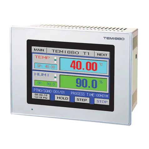
Samwontech TEMI 880 User manual

TEMI880
INSTRUCTION MANUAL
Temperature ∙Pressure Programmable Controller


TEMI 880
1
Catalog
1. Notice for Use....................................................................................................................................... 5
1.1. Limited Warranty.......................................................................................................................5
1.2. Warranty Policy......................................................................................................................... 5
1.3. Install Location Require........................................................................................................... 5
1.4. Install Notice.............................................................................................................................. 6
2. Appearance Dimension.......................................................................................................................7
3. Installation..............................................................................................................................................8
3.1. Body Terminal........................................................................................................................... 8
3.2. Applicable Tightening terminal............................................................................................... 8
3.3. I/O Relay Board.........................................................................................................................9
4. Input Keyboard................................................................................................................................... 10
4.1. Digital keyboard...................................................................................................................... 10
4.2. Alphabet keyboard..................................................................................................................11
5. Block Diagram of the Basic Processing......................................................................................... 12
6. Main Screen........................................................................................................................................ 13
7. Operation Screen............................................................................................................................... 14
7.1. Stop Screen............................................................................................................................. 14
7.2. Confirmation Window............................................................................................................. 16
7.3. Run Screen.............................................................................................................................. 17
7.4. Test Status................................................................................................................................18
8. Function Set Screen.......................................................................................................................... 19
8.1. Mode Set.................................................................................................................................. 20
8.2. Fix Set.......................................................................................................................................21
8.2.1. Slope Operation...........................................................................................................22
8.3. Waiting Set...............................................................................................................................23
8.3.1. Wait Function Operation............................................................................................ 24
8.4. Time & Reserve...................................................................................................................... 25
8.4.1. Reserve Method.......................................................................................................... 26
8.5. Normal Set............................................................................................................................... 27
9. Graph Screen......................................................................................................................................28
9.1. Highest and Lowest Display Point....................................................................................... 29
9.2. Curve Select............................................................................................................................ 29
9.3. Time Scale Zooming.............................................................................................................. 30

TEMI 880
2
9.4. File List..................................................................................................................................... 31
9.4.1. Historical File Manage................................................................................................ 32
9.4.2. Table Show...................................................................................................................33
9.4.3. Historical Files’ Order................................................................................................. 34
9.5. Other Set.................................................................................................................................. 35
10. Assistant Screen.............................................................................................................................. 36
11. Program Set Screen........................................................................................................................ 38
11.1. Edit Segment.........................................................................................................................39
11.1.1. Insert Method of Segment....................................................................................... 40
11.1.2. TS Set......................................................................................................................... 41
11.1.3. TS Operation within Segment.................................................................................42
11.2. Loop Set................................................................................................................................. 43
11.2.1. Segment Repeat Explanation................................................................................. 44
11.2.2. Program Repeat Explanation..................................................................................45
11.3. Other Set................................................................................................................................ 46
Caution…………………………………………………….........7, 12, 15, 16, 21, 31, 32, 38, 39, 46

TEMI 880
3
Attention
Thank you for purchasing our controller, this manual explains situation effective
way of using and installing this production.
1. Please keep the manual for the last user who can get easy access for the
manual.
2. Make sure read this manual carefully and fully understand how to operate this
product before operation.
3. This manual is intended to describe the functions and the operate way of this
product.
4. Redistribution & use this manual, with or without modification, are prohibited.
5. The contents of this manual are subjected to change without prior notice.
6. Every effort has been made to ensure accuracy in the preparation of this
manual. However, if any errors are found in this manual. Thank you for your
understanding.

TEMI 880
4

TEMI 880
5
1. Notice for Use
1.1.Limited Warranty
1We make no warranties regarding the product except these mentioned in the
Warranty.
2In cases where the use of this product results in damage or loss to the user or
a third party, we will not be responsible for any incidental or consequential
damage or loss, or any damage or loss suffered by the user or third party
resulting from a defect or defects in this product which could not be foreseen
by us.
1.2.Warranty Policy
1Warranty term is 1year parts and labor. We make warranties regarding the
product only these mentioned in the WARRANTY.
2A/S(After Sales Service) is needed actual expenses, after warranty period.
3This warranty does not cover damage due to loss password, accident fire,
flood and/or other acts of God; misuse, instability, improper installation,
improper or unauthorized repairs, commercial adjustments which are
explained in the instruction manual are not covered under the terms of this
warranty. This warranty automatically will be voided for any unit found with a
missing or altered serial number.
4All warranty repairs must be performed by our authorized service center.
1.3.Install Location Require
1No one may accidentally touch the terminals.
2Mechanical vibrations are minimal.
3Corrosive gas is minimal.
4Temp. can be maintained between 10℃to 50℃and fluctuation is minimal.
5Indoor use only.
6Altitude is up to 2,000m.
7No direct radiant heat or ultraviolet rays is present.

TEMI 880
6
8No magnetic disturbances are caused.
9No wind blows against the terminal board. Also no dust or salt content.
10 No flammable materials are around.
1.4.Install Notice
1There is little influence for electromagnetic fields and noise.
2No moisture can get into the system.
3Ambient temp. and Pressure : 10~50℃, 20~90%RH. (At non-freezing status).
Storage temp. and Pressure : -25~70℃, 5~95%RH. (At non-freezing status).
4If you want to use it after keeping it under 0℃, you need to warm it up for 2
hours at room temperature before plugging it in and warm it up for 30 minutes
after plugging it in. Otherwise, it may not function normally and the product
may be damaged.
5Do not use around any machine, which heat up. Avoid installing it with the
front facing slant.
6Transient over voltage category is categoryⅡ. Applicable rated pollution
degree is pollution degreeⅡ.
7Before starting wiring, be sure to turn off the system or else you will get an
electrical shock.
8Install the guard panel under the controllers for your safety and installation
with easy.
9The I/O relay board must be installed inside of Temp. & Press. Chamber.
10 The I/O relay board must be tied up with 4 pieces of bolt and nut at the 4 holes
on the I/O relay board.

TEMI 880
7
2. Appearance Dimension
TEMI880 Temperature ∙ Pressure Programmable Controller
Figure 2
Appearance and Mounting dimension:
1Appearance dimension: 184×144×107.7(mm) (L×H×W).
2Mounting dimension: 173×133(mm) (L×H).
CAUTION
► Before install & wiring, be sure to turn off the system or else you will get an
electrical shock.
► Do not tighten the mounting screw excessively; the unit case or bracket may
be damaged.
► Make sure ground with Temp. and Press. Chamber case when install power
injection.

TEMI 880
8
3. Installation
3.1.Body Terminal
TEMI880 Body Terminal
Figure 3
3.2.Applicable Tightening terminal
Please use-tightening terminal with insulating sleeve for M3.5 screws as following:
Figure 4

TEMI 880
9
3.3.I/O Relay Board
I/O Relay Board Terminal
Figure 5

TEMI 880
10
4. Input Keyboard
Digital keyboard use for input setting value, alphabet keyboard use for edit the
PROGRAM or DI name.
4.1.Digital keyboard
Digital Keyboard
Figure 6 Figure 7
1Data range: valid data range.
2.: decimal point.
3-: input sign (“-“).
4OK: save input data and close the keyboard.
5Esc: cancel input setting value.
6OFF: click on it to close the keyboard.
7DEL: modify the input data, delete one by one.
8Title: notice the subject.
9CLR: clear all input data.
②
⑥
③
④
⑤
⑦
⑧
①
⑨

TEMI 880
11
4.2.Alphabet keyboard
Alphabet Keyboard
Figure 8
1ABC: escape character (ABC / Chinese / Symbol, and so on).
2Space: space button.
3Next line: jump to next line.
4: delete all input data.
5: back to last step.
6: save input data and go back to last step.
7: page up or down.
8: modify the input data, delete one by one.
9Full: full screen display.
①
②
⑨
⑧
⑦
⑤
③
④
⑥

TEMI 880
12
5. Block Diagram of the Basic Processing
Initial Screen
Figure 9
Main Screen Oper. Screen
Figure 11 Figure 10
Power ON will display Initial Screen and waiting for 15 seconds to enter Monitor
Screen, click on the “MAIN” pattern can enter Main Screen as Figure 11.
CAUTION
► When connection, do not mix up the input polarity. Connection with the wrong
polarity can cause the unit to malfunction.
► Please do not use any pen/pencil, nail or any other sharp material to touch
screen. Otherwise, the touch screen might be broken or out of order.
Power ON

TEMI 880
13
6. Main Screen
Main screen is center of the other screen transfer; other screens can be entered
through it. Click on this pattern in any screen to return to the main screen.
Main screen
Figure 11
1OPER. SCR: click on the “OPER. SCR.” button to enter the Operation Screen.
See 7. Operation Screen
2Func. Set: click on the “FUNC. SET” button to enter the Function Set
Screen. See 8. Function Set Screen
3Graph: click on the “GRAPH” button to enter the Graph Screen.
See 9. Graph Screen
4Assistant: click on the “ASSISTANT” button to enter the Assiatant Screen.
See 10. Assistant Screen
5PROG Set: click on the “PROG SET” button to enter the Program Set Screen.
See 11. Program Set Screen
②
③
④
⑤
①

TEMI 880
14
7. Operation Screen
Click on “OPER. SCREEN” button in Figure 11 to enter Operation Screen.
7.1.Stop Screen
Fix Mode Stop Screen
Figure 11
Program Mode Stop Screen
Figure 12
1: “HOME” button, click on it can back to Main Screen.
2SV: In Fix mode, display setting value, and click it can set test Temp & Press
value directly. In Program display the current segment’s setting value.
②
⑩
⑪
⑤
①
⑥
⑦
⑧
⑫
⑬
③
④
⑨

TEMI 880
15
3Fix stop: display the test state and program’s NO.
4Time button: display controller current time.
5: test status warning button, Stop/Run. In other screen click on it once shift
to Monitor Screen, twice for come back.
6: function 1, click on it to turn ON or OFF keyboard locked function directly;
function 2 notice keyboard locked or unlock. When keyboard had locked user
cannot operate until input the right password.
Password setting please See 10. Assistant Screen
7: notice that U-Disk had inserted.
8Title: notice the content of current display screen.
9PRE-H : setting Preheat value, when TPV ≥Pre-H SV “PRE. AL” will effect .
User click on this button to close alarm and Press will start run.
10 : display the test status, click on this button shift to Test Status, click it
again for back. See 7.4 Test Status
: function set, click on this button to enter Function Set Screen.
See 8. Function Set Screen
: back to last step.
: run/stop button, click it will pop up the Confirmation Window to select
start or stop the test. See 7.2 Confirmation Window
CAUTION
► Support file format of U-disk:
Before export or import the data from/to USB, please make a right-clicking to
check the file system attribute of U- disk (we suggest using 8G memory USB).
Our controller support “FAT16”, “FAT32” and “FAT12” file system attribute,
except “NTFS”.
► Run mode and current running Program’s data can’t be modified when running
⑬
⑪
⑫

TEMI 880
16
7.2.Confirmation Window
Click on the button in Figure 10/12 it will pop up the Confirmation Window as
Figure 13/14.
Fix Mode Confirmation Window Program Mode Confirmation Window
Figure 13 Figure 14
1Pause: pause the test, click it again will keep running and recording time.
2Stop: stop the test, clear the record time, build a new historical curve file.
3Start: start the test, or disarm the pause status.
4AT: enable or disable the Temp/Press auto-tuning under current setting point
status. Turn ON AT function See 10. Assistant Screen
5Jump: stop the current running segment and jump to next segment.
6Hold: hold ON or OFF the current setting point.
CAUTION
► The distinction between PAUSE & STOP:
“STOP” means stopping current running test, clear the record time then build
up a new historical curve file.
“PAUSE” means pausing the current running test, click it again will keep
running this test and recording the time.
► AT function is available on Fix Mode only.
► Jump & Hold function is available on Program Mode only.

TEMI 880
17
7.3.Run Screen
FIX Mode Run Screen
Figure 15
PROGRAM Mode Run Screen
Figure 16
1MV: display the Temp./Press. MVOUT.
2Run time: in Fix mode will display the current test total running time.
In Program Mode will display total running time, and current running
program NO(001)/ segment NO(001).
3Deflate: turn ON or OFF Deflate function.
Seting its action mode See 10. Assistant Screen
4The press status display: display the current test pressure value.
5The temp. status display: display the current test temperature value.
6Status display arrow: display current test subject’s status, up/keep/down.
7Add gas: turn ON or OFF Add Gas function.
①
⑤
②
②
⑦
③
④
⑥

TEMI 880
18
7.4.Test Status
Click on button in Figure 10/12 shift to Test Status screen as Figure 17/18.
FIX Mode Status Screen
Figure 17
PROGRAM Mode Status Screen
Figure 18
1PV: display the present test value of test.
2Status display lamp: each of them represents a relay signal, when relay is
work, corresponding lamp will turn red.
3Remain: in Fix mode display the remaining time of total set time, in Program
mode display the remaining time of current running segment’s set time.
4Set time: in Fix mode display total setting time of test, in Program mode
display setting time of current running segment.
5PTNO/SEG NO.: display current running program’s PROG. NO./ SEG. NO.
6Cycle: display program cycle count, cycled count (001)/ cycle set count (003).
See 11.2 Loop Set
7Part loop: display segment cycle count, cycled count (001)/ cycle set count
(002). See 11.2 Loop Set
⑤
⑦
⑥
①
②
③
④
Table of contents
Other Samwontech Temperature Controllers manuals
Popular Temperature Controllers manuals by other brands

Honeywell
Honeywell MICRONIK 200 R7426A Installation & start-up instructions

Samson
Samson 2432 Mounting and operating instructions

Siemens
Siemens RDF20U installation instructions

ALSENSE
ALSENSE ALS Brake Wired install guide

Tempatron
Tempatron TC4800 Series manual

EUTECH INSTRUMENTS
EUTECH INSTRUMENTS Digi-Sense 68900-01 instruction manual