S&B Filters 76-2000 User manual

SEE EXPLODED VIEW ON PAGE 7
15461 Slover Ave., Fontana, CA 92337 - Phone: (909) 947-0015 - Fax: (909) 947-0603 - www.sbfilters.com
1
INSTALLATION INSTRUCTIONS
P/N: 76-2000
Approx. Install Time: 2Hrs 00Min
VEHICLE APPLICATION
Year: 2014 - 2016
Make: Polaris
Model: RZR 1000, XP4
Engine: 1000cc, Turbo (2016)
TOOLS REQUIRED
•2.5mm, 4mm, 5mm Hex Key
•10mm Wrench/Socket
•5/16 Nut Driver
•Phillips Screwdriver, Flat Blade Screwdriver, Razor Blade, and Wire
Cutters
WARNING:
THIS EQUIPMENT SHOULD BE INSTALLED, ADJUSTED, AND SERVICED BY PERSONNEL FAMILIAR WITH THE
CONSTRUCTION AND OPERATION OF THIS TYPE OF EQUIPMENT AND THE HAZARDS INVOLVED. FAILURE TO
OBSERVE THIS PRECAUTION COULD RESULT IN SEVERE INJURY. READ THIS MANUAL THOROUGHLY AND MAKE
SURE YOU UNDERSTAND THE PROCEDURES BEFORE YOU ATTEMPT TO OPERATE THIS EQUIPMENT. THE
PURPOSE OF THIS MANUAL IS TO PROVIDE YOU WITH INFORMATION NECESSARY TO SAFELY OPERATE,
MAINTAIN, AND TROUBLESHOOT THIS EQUIPMENT. DO NOT USE THIS EQUIPMENT FOR ANY REASON OTHER
THAN ITS INTENDED PURPOSE. FAILURE TO FOLLOW THESE INSTRUCTIONS WILL VOID ANY WARRANTY. KEEP
THIS MANUAL FOR FUTURE REFERENCE. THE INFORMATION CONTAINED IN THIS MANUAL IS SUBJECT TO
CHANGE WITHOUT NOTICE.
Product will intake and expel both air and loose materials with high force and velocity.
•Install product on roll cage, so air inlet is not blocked.
•Do not place face, hair, extremities, clothing, or other loose material in front of air inlet or outlet during use.
•Install product securely to roll cage and avoid placing hair, extremities, clothing, or other loose material in front of air inlet
during use.
Moving parts are sharp and could cause personal injury.
•Keep fan safety guard and exhaust cover in place while operating and after service.
•Disconnect product from power source before servicing.
Scavenge Fan is designed for use in conjunction with an UTV’s operating manual, and state and federal law.
•Keep your seat belt fastened and wear a helmet while operating the vehicle.
Risk of electric shock!
•Improper installation, maintenance or operation could cause serious injury or property damage.
BEFORE YOU START
•Please read the entire installation manual before proceeding.
•Ensure all components listed on page 10 are present.
•If you are missing any of the components, call our customer support at (909) 947-0015.
•Do not work on the vehicle while the engine is hot.
•Make sure the engine is turned off, the vehicle is in Park and the Parking Brake is set.
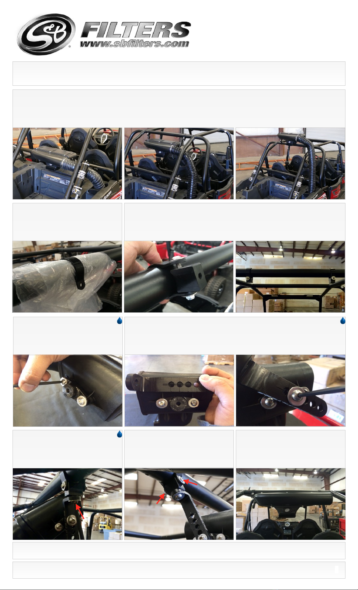
THREAD LOCKER USE
We have provided a small tube of thread locker in your kit.
Whenever you see the symbol above on a step of the
instructions apply 1 small drop of the thread locker to the
threads of the screws or bolts. This will keep your
hardware from vibrating loose during rough driving. If the
hardware ever needs to be removed, do so slowly to avoid
having the inserts strip out from the plastic.

INSTALLATION INSTRUCTIONS (CONTINUED)
SEE EXPLODED VIEW ON PAGE 7
15461 Slover Ave., Fontana, CA 92337 - Phone: (909) 947-0015 - Fax: (909) 947-0603 - www.sbfilters.com
2
1. Determine where on the roll cage you want to mount the Particle Separator (A). Make sure you have enough room to fit the clamps and particle separator on the
roll cage without any interference. Planning ahead will save you time and frustration during the install. Our clamps are adaptable enough to work around any
additional accessories you may have on the roll cage in addition to the particle separator.
2. At the mounting locations determined
previously, install the Strap (O) onto the roll
cage. Loosely wrapping some plastic around
the roll cage will help sliding the strap onto the
roll cage easier and prevent scratches.
3. Install the Pivot Body (N) onto the Strap (O) with the supplied Screw (S), Locknut (T), and Washer
(D) on the roll cage. Do this for both sides. Do not fully tighten the screws and locknuts. Leave the
strap loose.
P/N: 76-2000
4. Install the Adapter (F) on the mounting bosses of the
Particle Separator (A) with the supplied Screw (P) and
Washer (D). Tighten these screws. Do this for both sides.
8. Go over all the screws and locknuts again
to make sure they are secure and that the
Particle Separator (A) is firmly attached to the
roll cage.
7. Once you are satisfied with the position,
tighten the Screw (S), Locknut (T), and Washer
(D) at the Strap (O). Do this for both sides.
6. Install the L Bracket (M) onto the Pivot Body (N)
using Screw (R) and Washer (Q). You may have to
adjust the position of the Strap (O) and pivot body to
get the holes to line up. Do this for both sides. Having
an extra pair of hands holding the Particle Separator
(A) to help line up the holes will make the install easier.
5. When installing the L Bracket (M), make sure the ribs in the L Bracket are properly seated inside the grooves of the
Adapter (F). Any misalignment will damage these parts. Do not attempt to rotate these parts once assembled. They are
designed to lock into place once seated. Determine the proper angle to mount the L Bracket (M) to the Adapter (F) based on
the desired location for the Particle Separator (A). Make sure the L Bracket is properly seated on the adapter before tightening
it in place with the Screw (R) and Washer (Q). Do not tighten the hardware if these parts are not seated properly or damage
may result. Repeat for the other side of the Particle Separator and make sure the L Bracket on both sides are pointed in the
same direction and are aligned with each other.

INSTALLATION INSTRUCTIONS (CONTINUED)
SEE EXPLODED VIEW ON PAGE 7
15461 Slover Ave., Fontana, CA 92337 - Phone: (909) 947-0015 - Fax: (909) 947-0603 - www.sbfilters.com
3
P/N: 76-2000
16. Install the Duct (E) onto the Duct Adapter
(F) and tighten Hose Clamp #56 (O).
18. Install the Side Cover (B). Use a 4mm hex key on the Screw (C) and Washer (D) to secure the
side cover to the body.
17. Insert the there end of the Duct (E) into
the plenum on the Particle Separator (A).
Tighten Hose Clamp #56 (O).
15. (Optional) For a cleaner appearance, take
the end of the wire and tuck it inside the duct.
Do this for both ends of the duct if needed.
14. (Optional) Regular staples can be used to
secure the ends of the strings to the duct.
12. Pierce the Duct (E) using a razor,
centered between the two wire reinforcements.
Cut all the way around. Try to cut the duct
straight around the center as close as possible.
13. Use scissors to begin the cut. Aim the
scissors towards the start of the cut. Do not try
to cut through the wire with scissors. Use a
mini-bolt or a heavy duty wire cutter to finish
cutting through the wire and strings.
11. Insert one end of the Duct (E) onto the Duct
Adapter (F).Bring the other end towards the plenum
on the Particle Separator (A). Note the length on the
duct you want to cut. We recommend cutting the duct
an extra 3" longer so that the ends, along with any
wire and strings, can be folded in for a cleaner look.
10. Place a Hose Clamp #56 (G) over the
stock air box inlet. Install the Duct Adapter (F)
into the stock air box inlet with the larger OD
facing up and tighten the hose clamp.
9. Loosen the screw at the passenger side frog skin side cover. Lift up and pull towards the front of
the vehicle to remove the frog skin side cover.

INSTALLATION INSTRUCTIONS (CONTINUED)
SEE EXPLODED VIEW ON PAGE 7
15461 Slover Ave., Fontana, CA 92337 - Phone: (909) 947-0015 - Fax: (909) 947-0603 - www.sbfilters.com
P/N: 76-2000
25. Find Wire B and strip about 3/8” off the end of the wire. Route the wire along the frame and
hoses toward the tail light assembly. Route the harness so that the wires will not get damaged from
heat, the environment or pinched while the UTV is operating.
26. There are two options to tap into the power
source. One is at the tail light assembly itself and
the other at the main taillight connector. Read
through Step 33 - 40 and choose one that you
prefer before installing the stripped wire.
2nd Option
1st Option
23. Remove the nut from the negative battery terminal
clamp and disconnect the terminal from the battery. Then,
remove the nut from the positive battery terminal clamp.
Install the ring terminals onto the battery terminal clamps.
Red wire with the fuse holder to (+) and Black wire to (-)
and reinstall the nuts. Secure the positive terminal first and
then secure the negative terminal.
24. Reinstall the seat. Look for the two seat tabs at the base of the seat. Slide the tab through metal
rail first and then push the seat down. You should hear a click when the adapter on the bottom of the
seat snaps into the seat adapter.
Seat Tabs
Seat Rail
Seat Adapter
20. Familiarize yourself with the Wire Harness (J) and each of the connectors. Coming from the
relay should be three branches. Connector A has the fuse holder with the red and black ring terminals
for the battery. Wire B is used with the Posi-Tap (U) to tap into a power source. Connector C has the
connector to power the Particle Separator (A) exhaust fan.
B
A
C
21. Remove the rear driver’s side seat by
pulling the latch under the seat and lifting up to
reveal the battery compartment. If the vehicle is
a two-seater, remove the driver’s seat.
22. Find Connector A. Feed the terminals and fuse holder into the gap behind the rear driver’s side
fender. This gap goes to the battery compartment.
To Battery Compartment
19. Use the provided Velcro Strap (H) to
secure the Duct (E) to the roll cage.
B
A
C
Relay
Fuse Holder
4

INSTALLATION INSTRUCTIONS (CONTINUED)
SEE EXPLODED VIEW ON PAGE 7
15461 Slover Ave., Fontana, CA 92337 - Phone: (909) 947-0015 - Fax: (909) 947-0603 - www.sbfilters.com
P/N: 76-2000
28. Find the Taillight Adapter (K) provided. This will
be used to tap into the wire harness assembly
connector.
30. Screw the body around the cap until it is
firmly tight.
31. Unscrew the bottom cap on the Posi-Tap
(U) and insert the Wire B through it.
27. 1st Option, use this option if you are not comfortable tapping into the factory wire harness. We
provide a Taillight Adapter (K) that you can tap into instead. Disconnect the connector on the driver
side taillight assembly. If necessary use a flat head screwdriver to spread out tab slightly so you can
pull the connector out.
29. Use the supplied Posi-Tap (U) and
unscrew the large top cap. Place the cap in
between the red wire on the Taillight Adapter
(K). This will be your power source.
Goes Into Taillight
Assembly
Goes Into Stock
Taillight Connector
35. Find Connector C.
34. Find the red/yellow wire for the taillight connector. Use the provided Posi-Tap (U) and tap into
the red/yellow wire. Make sure both the top and bottom caps on the Posi-Tap are tight. Use Cable
Ties (I) effectively to secure the harness away from any exhaust components or moving parts that
could potentially damage the harness.
32. Insert the wire into the Posi-Tap, making sure the strands go around the metal core. While
holding the wire in place, screw the bottom cap back on until it is firmly tight. Double check both caps
to make sure they are tight. Connect the Taillight Adapter (K) into the taillight assembly and then into
the stock taillight connector. Use Cable Ties (I) effectively to secure the harness "away from any
exhaust components or moving parts that could potentially damage the harness.
33. 2nd Option, use this option if you are
comfortable tapping into the factory wire
harness. Look for this taillight connector behind
the exhaust. Its out in the open so it should be
quite easy to find.
5

SEE EXPLODED VIEW ON PAGE 7
15461 Slover Ave., Fontana, CA 92337 - Phone: (909) 947-0015 - Fax: (909) 947-0603 - www.sbfilters.com
INSTALLATION INSTRUCTIONS (CONTINUED)
P/N: 76-2000
ONGOING MAINTENANCE
Your Particle Separator requires very little if any maintenance depending on where you drive; however,
you should check to make sure that none of the openings on front of the Particle Separators are blocked
by mud or other debris each time you exit the UTV. You should also make sure the scavenge fan is
operating properly. To do so, simply check to make sure the fan is still blowing out air (for about 15-20
seconds) when you turn off your UTV as this is a normal condition. If the fan is not blowing out air or the
airflow seems lower than when you initially installed your system, please contact S&B tech support. To
clean your Particle Separator, review the cleaning instructions below.
40. Make sure the connectors are all plugged in and
secure. Turn the ignition on and make sure air is
blowing out the exhaust. If air is not blowing out, double
check your electrical connections. When you turn the
ignition off, the fan will stay on for several seconds, and
is normal. Your installation is now complete.
RELATED ITEMS FOR YOUR
PURCHASE
•Clutch Ventilation System (Coming Soon)
•Air Intake System (Coming Soon)
•Stock Replacement Filter (Coming Soon)
Order online today at www.sbfilters.com or
through your local S&B distributor.
SIDE NOTE
S&B recommends that you apply a layer of waterproof grease, such as made by Bel-Ray or Super
Lube, on the inside flange of the stock air filter to keep dust from bypassing the seal.
39. Group together any excess wires and Cable Tie (I) them together. Use another cable tie and
secure the bundle in places away from any exhaust components or moving parts that could
potentially damage the harness.
36. Route Connector C up the roll cage. and connect the harness into the fan connector on the Particle Separator (A).
38. Use the Cable Ties (I) or Velcro (H) provided to secure the wire to the roll cage.
To Battery
Compartment
37. Note the color of the wires whenever
connecting or disconnecting this connector. Make
sure not to cross the connectors. Power to power and
ground (black) to ground (black). The connector
should snap into each other with very little resistance.
Do not try to force the connectors into each other.
To Particle
Separator
6
Table of contents
Other S&B Filters Automobile Accessories manuals
Popular Automobile Accessories manuals by other brands

SPIKES-SPIDER
SPIKES-SPIDER Sport operating instructions

T.J.M.
T.J.M. T13 Outback Frontal Protection System Fitting instructions

Westin
Westin 40-0245 installation instructions

Allen Sports
Allen Sports 102DN instructions

Thule
Thule Rapid System Kit 1449 instructions

Polaris
Polaris 2883419 quick start guide